Machine Building
Our Machine in Action
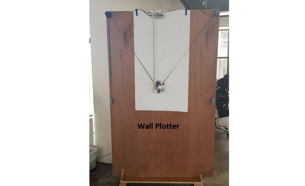
This week’s group’s assignment was to build our own machine.
We all decided to make a wall plotter :)
Center Piece Creation
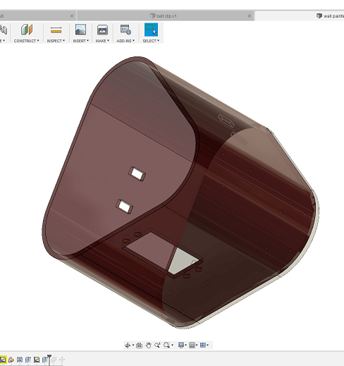
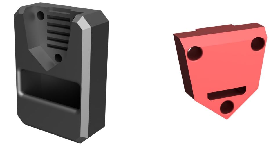
Next is designing the center piece that will hold the pins and servo motor. My colleague Tarek had already designed the marble balls holders, which will be used to make the piece's movement smoother against the wall, and my colleague Ahmad designed the pins' holder which will rotate to change pens.
we started our design process by checking the machines available online for the same purposes. we tried to understand the components and arrangements, and the value of each component in the design. After I had a clearer understanding, I started designing process on Fusion360. The first design I made had few points that could have been enhanced for an optimum design, which are:
- Increasing the distance between the ball holders, placing them closer to the corners than the center.
- Cutting the depth of the machine to the smallest depth possible to take advantage of inertia.
so, what we did is we went back to the design, increased the distance between the ball holders, and made the size of the tail smaller, this is the final design
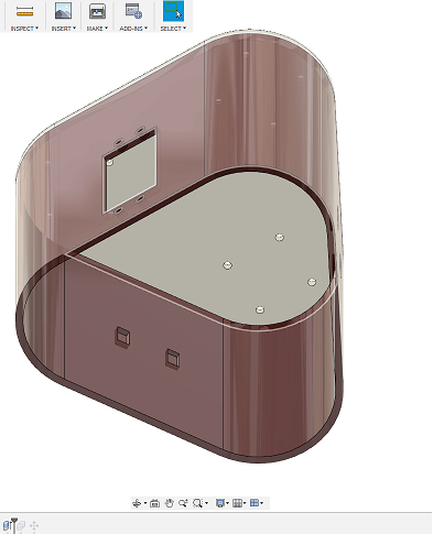
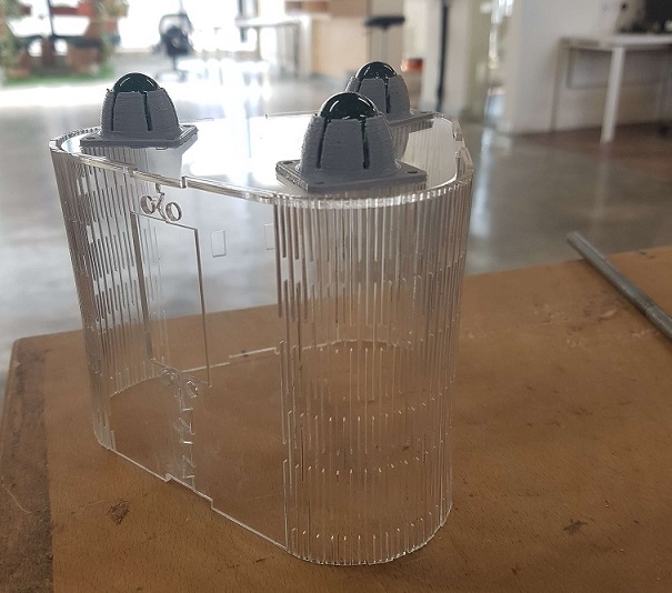
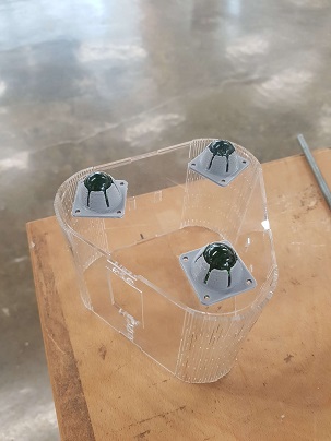
Now that it was ready and the whole team agreed to it, I made the 2D plans on CorelDraw, and then made them using laser cutting.
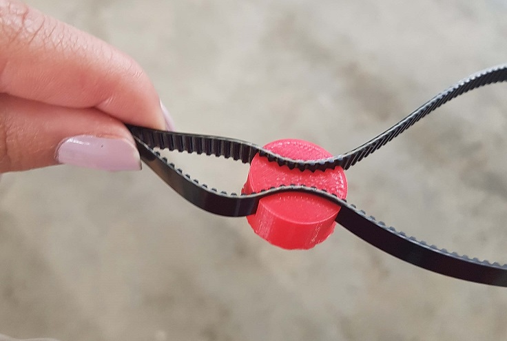
Next, we designed the belt clips, again using fusion 360, it’s a simple design of a small cylinder with belt shaped cuts in it. This is how it looked:
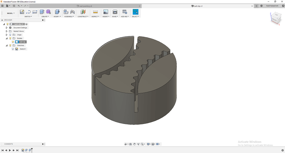
And we 3d printed the pieces, and then tested them with the belt. It was a tight fit, which means it would hold the machine in place.
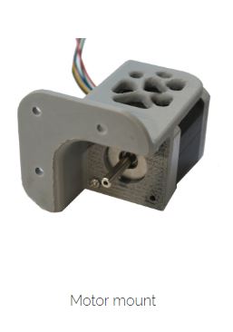
Motor Mount
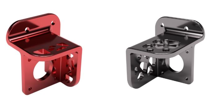
To mount the motors on the wall we measured the dimensions of the NEMA-17 motors available and designed a motor mount with some parametric patterns to decrease the ammount of material used, as well as make it more aesthetic. Initially, it only covered half of the motor height, but we later decided to cover the whole motor to make it look better.
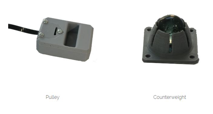
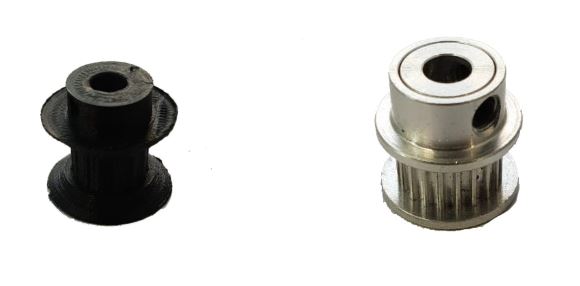
The arm controlled by the stepper motors is a geared belt as it doesn't stretch with force and fits this specific application. We had some pulleys in the store, but when we came to try them on, it turned the socket was way to big for the stepper motor's shaft. I therefore went and designed some pulleys to be 3d printed. Although the pulley worked relatively okay, I decided to salvage some pulleys from old unused 3D printers we had.
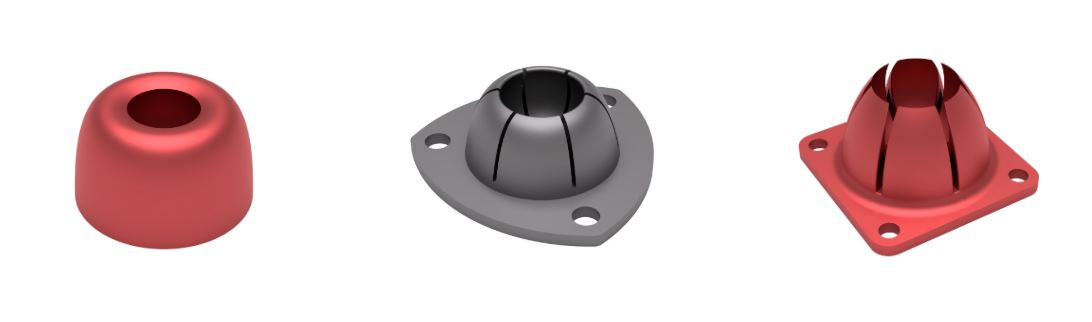
The final component of the stepper motor side is the counter weight for the belts. Since our approach was a parallel design approach rather than a waterfall approach, I had to design the counterweight to be modular. Meaning, depending on how heavy the main piece turned out, more weight could be added or removed, by having a pocket into which the weight is inserted. The counterweight piece, also had a complementary piece to lock the belt in place.
We also worked on developing the marble rollers that will be attached to the bottom of the main piece. They will act like omniwheels and allow sliding of the piece along the wall in any direction with limited friction. This was rather tricky as I tried several approaches, after which I experimented with different tolerances to get tackle fixing of the marble, smooth rolling with only rotation and no translation. The first approach was inserting the marble mid-print, which turned out quite tricky as the nozzle would come in contact witht the marble. The second design was push to snap approach which worked but was too bulky and once the marble was inserted, it couldn't be removed. The third design is the final one we settled on and was a push to snap approach as well, but allowed removal of the marble if required.