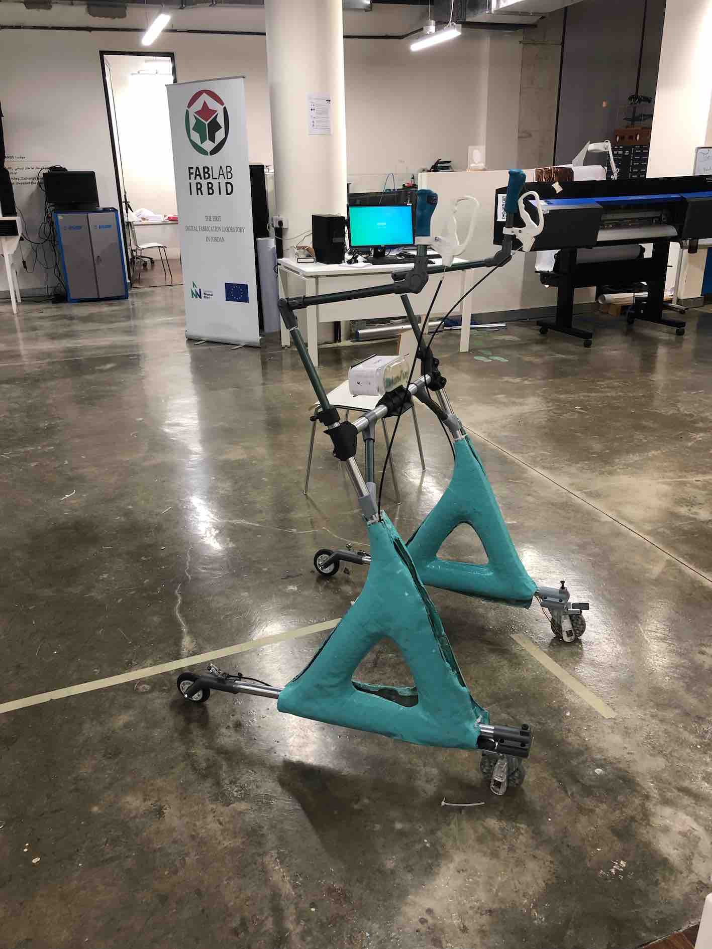
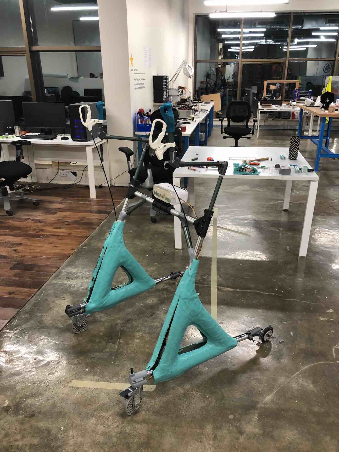
For my final project, I have decided to design and build a smart walker with a modular approach tailored for patients with hemoglobin deficiency and oxygen saturation problems. The technology implemented within the walker can be also integrated in other devices or standalone device that can be carried with you. My idea is to include features such as a socket to hold an oxygen canister, oximetry and heartbeat sensors on the handle as well as being able to calculate the distance moved and alert nearby persons if the patient has fallen or is in need of medical help.
Market Research
Firstly I researched demographic figures and statistics regarding walker patients in order to evaluate the usefulness and application of my project.
Icons for statistics
Statistics
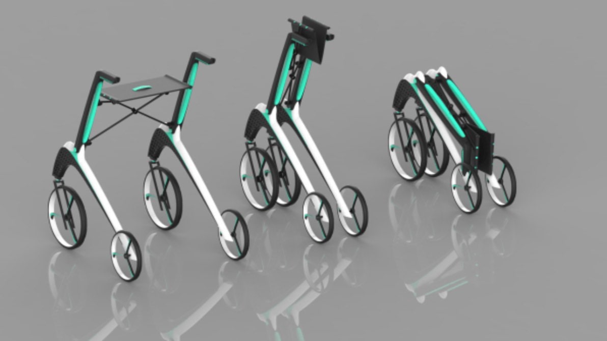
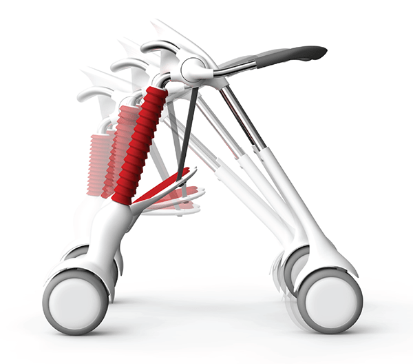
I then surveyed design-forward rollators and walkers to get some inspiration and ideas regarding the general shape of the walker. I found a very attractive walker by Yanko Design . I also found the Lio walker, developed by students to be a 3D-printed stylish walker.
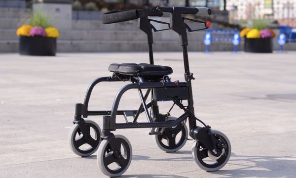
I researched walkers and rollators that are on the market or being developed with smart features and additional capabilities. I found the sentry scientific walker which incorporates automatic speed control and automatic braking features. The leapfrog had a mechanically-activated chair-locking feature to stop the walker from moving when a person is sitting on it.
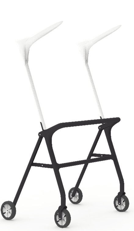
The , developed by students of Virginia tech, tackles a very important fall through of standar walkers and rollators. It includes very interesting design feature from a biomechanical point of view, where it ensures a correct upright posture for walker users. Coming from a biomedical engineering background, this feature has to be included within my design.
Ideation
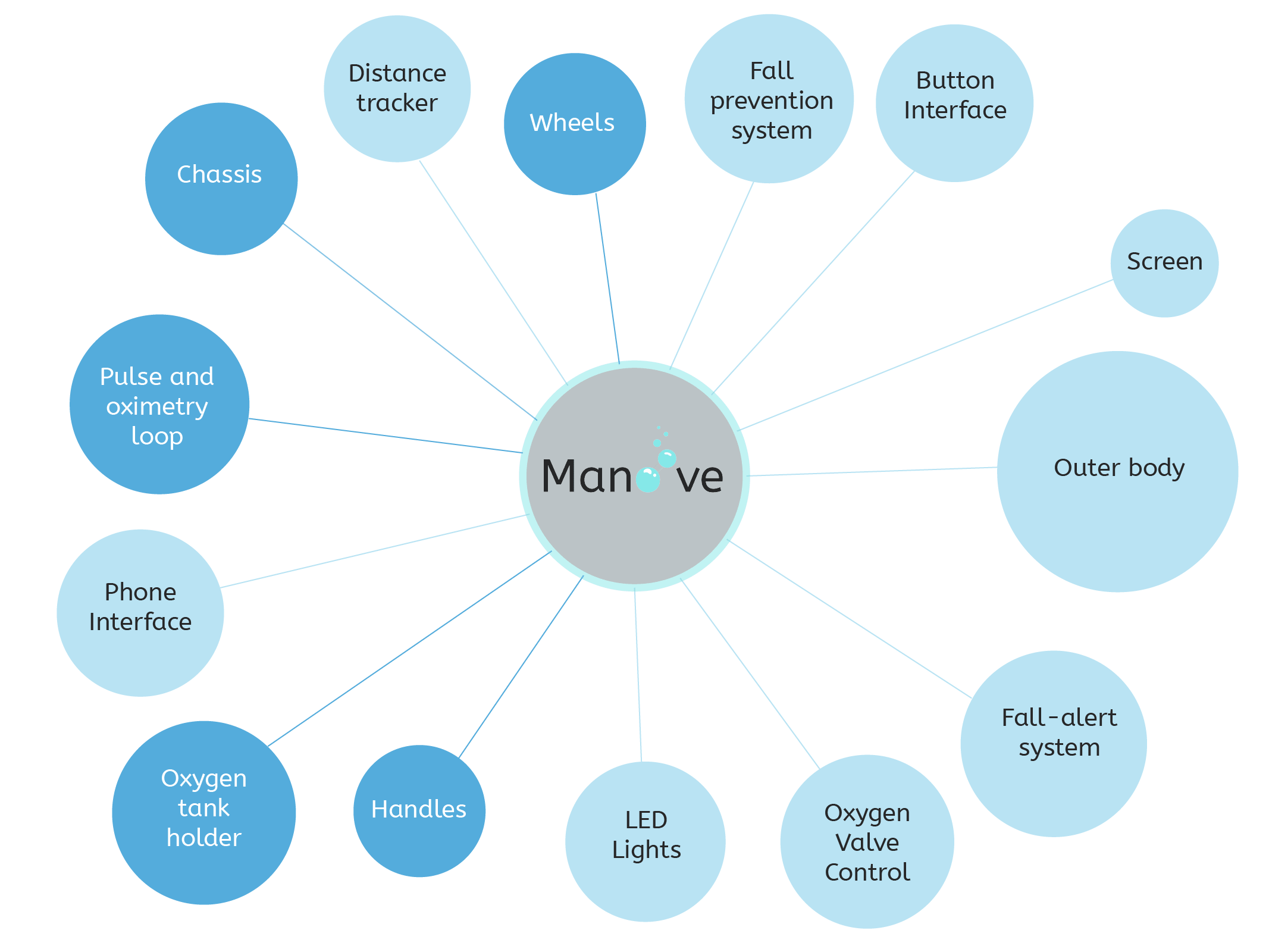
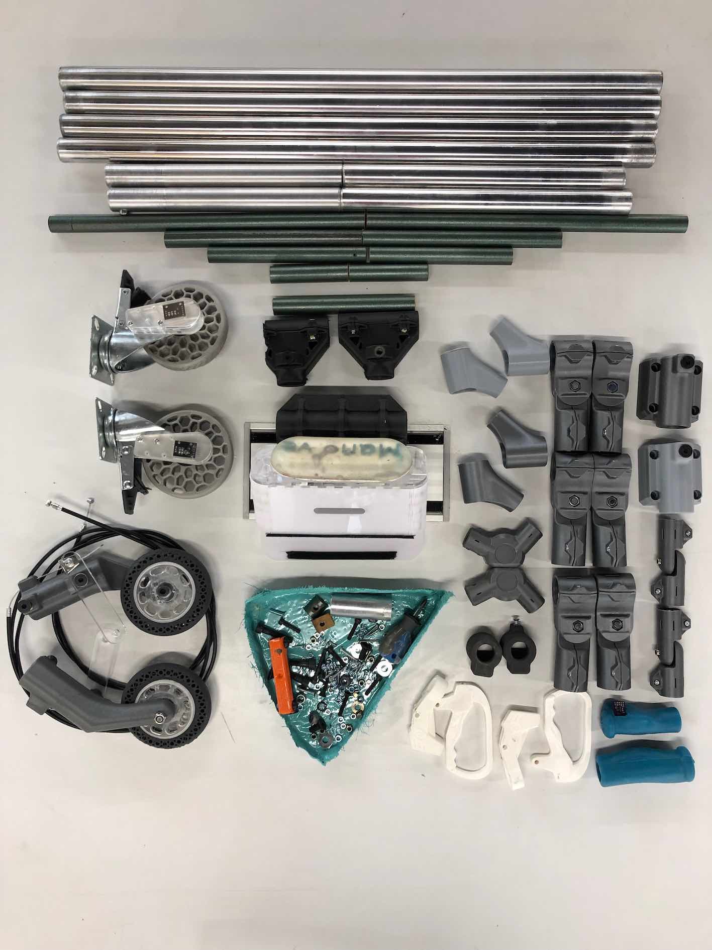
As explained in the planning section of week 1, I will organize the final product into modular components. Some which are integral for the functioning of the product, shown in navy blue. Other components are not required but will increase the capabilities of the device, shown in light blue. In most sections of this page I will adress each module individually, until the point of assembly where a full evaluation of the completed product is require.
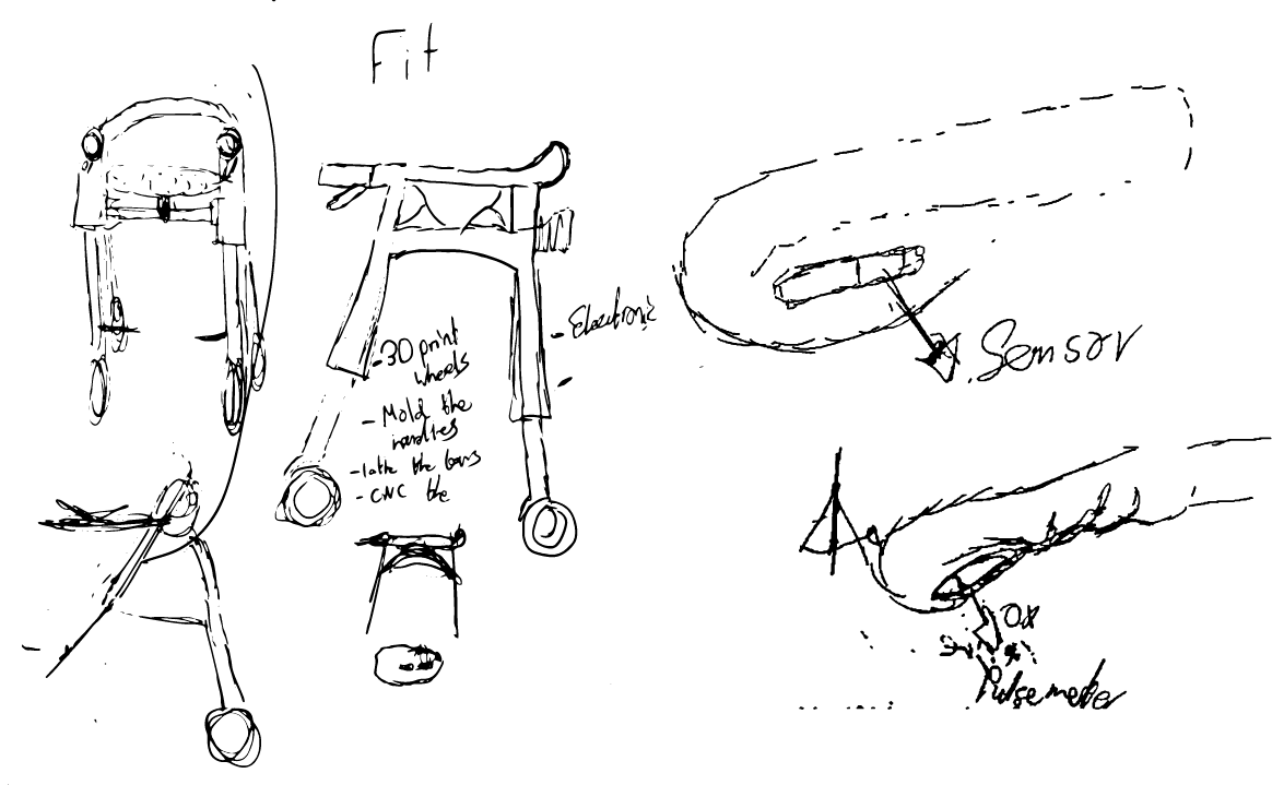
The ideation process involved a lot of sketching and rough ideas that I would jot down every now and then. This included all aspects, from the handle to the wheels.
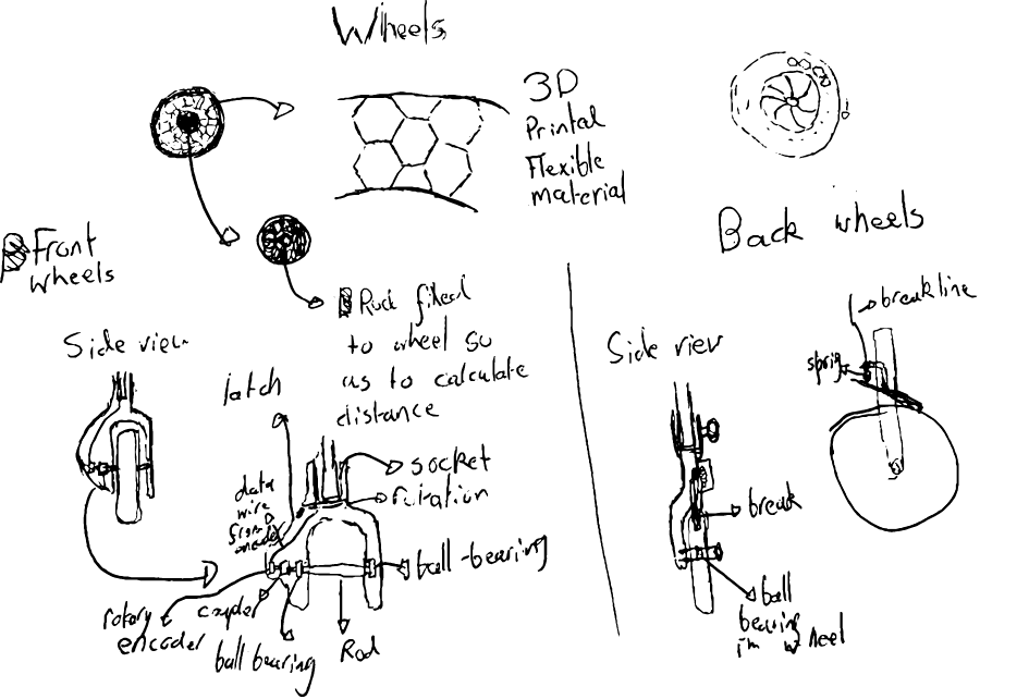
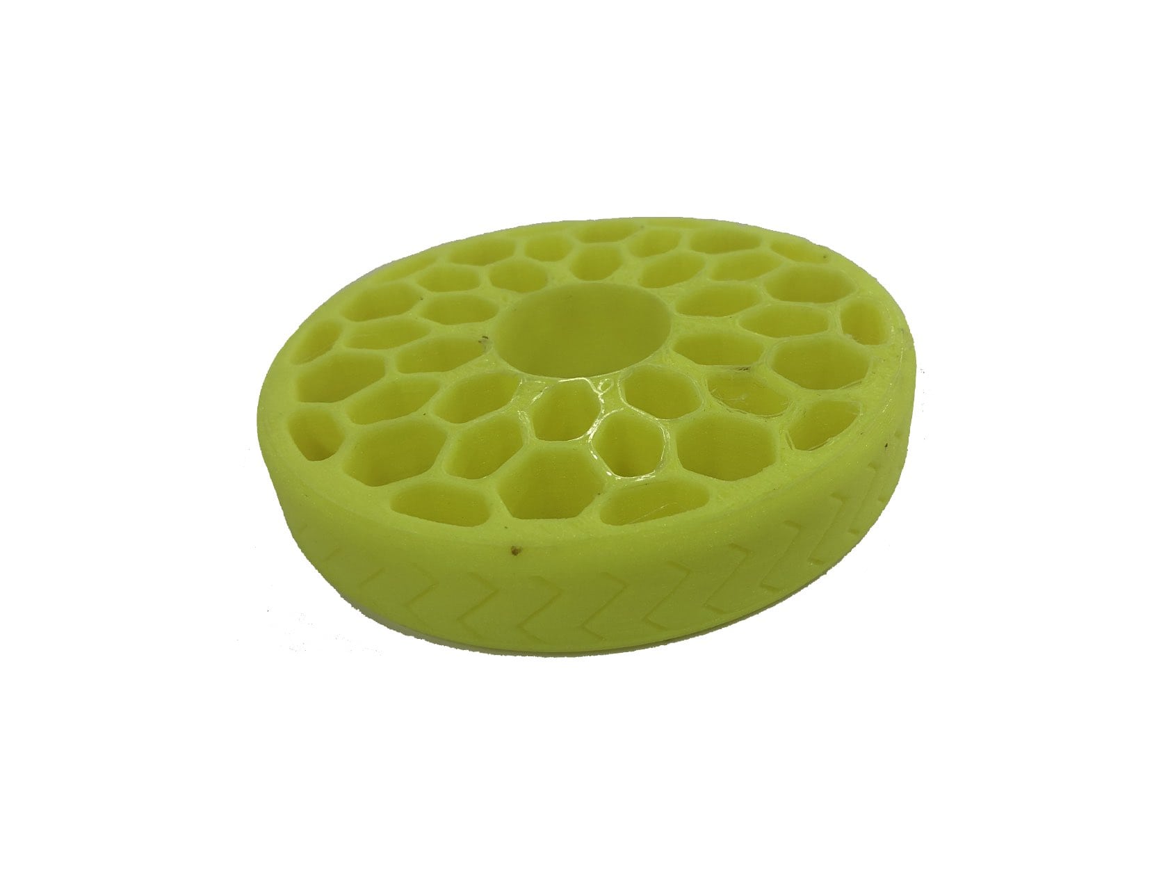
I sketched the wheels aiming to design a high traction, all-terain wheel system without the need for air pressure or hard cast rubber. The inspiration for the wheels are airless tires that are being developed for cars and automobiles. The front and back wheel have different approaches due to different loads and to allow the walker to go up a step if needed without having to carry it up.
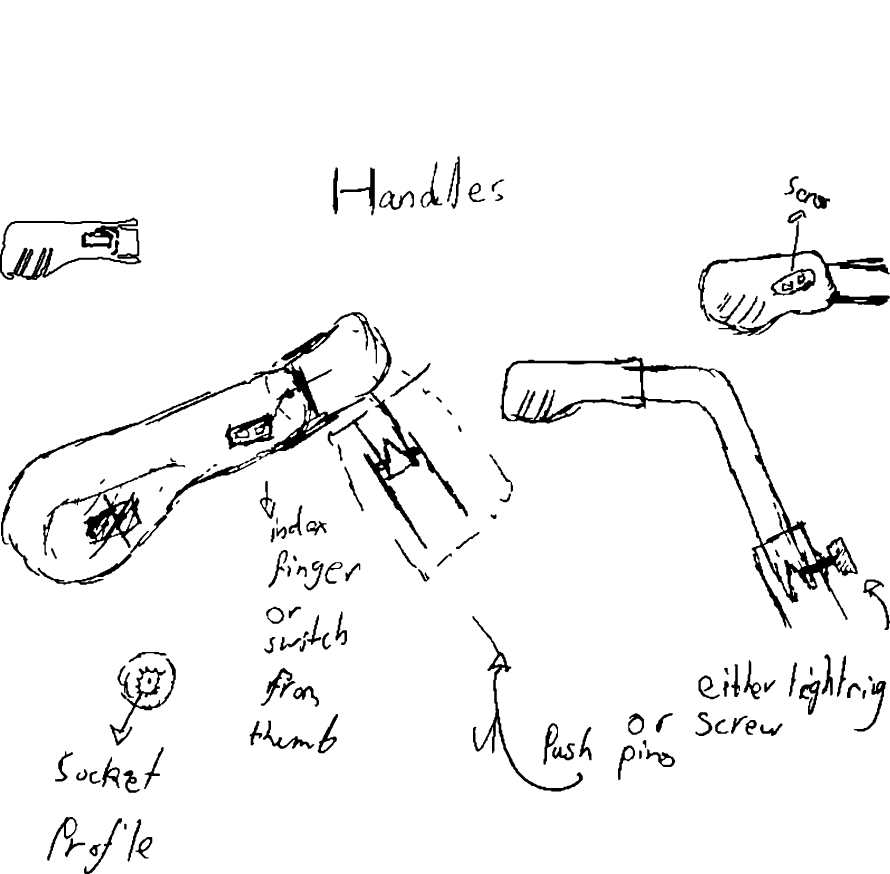
The handle will have a sensor built in and depending on which side the sensor is placed, the reading can be take from the thumb or index finger, increasing the modularity of the oximeter and HR sensor. Also the height of the handles can be changes. Two mechanisms are possible, either a pin and spring which fix into pre-drilled holes, or a tightening screw.
Design and Render
Bill of materials
The following bill of materials is an approximate and the complete accurate list will be available, including the exact quantities, at completion of the project, as some parts might change or others added.
Material
Cost(USD)
Aluminum and Fiber tubing
100
PLA Filament
40
Flexible Filament
10
Acrylic
10
Silicone
10
Wax Blocks
10
Screws and Nuts
~5
PCB material
10
Bluetooth Module
15
Accelorometer
10
Oximeter
25
Rotary Encoder
3
Total
250
Chassis Inspiration, ideation and design
For the chassis, I was inspired by the modern approaches to such mobility products but decided to allow changed to the angles and lengths of the chassis. This allows for a more customizable approach which is only made semi-permanent once the outer body is attached. My approach was inspired from adjustable PVC pipe joints and fixed bike joint that I had come across. Instead of PVC pipes I was planning on using aluminum pipes but then integrated fiber tubes which I discovered at the metal shop, they were lighter and strong enough for shorter, less load bearing parts of the rollator.
Metal and Fiber
The aluminum and fiber tubes were purchased in a very unfinished state, so I first had to finish and polish them before being able to continue in the manufacturing process. This was done by first sanding it on the lathe, starting with low grit sandpaper and slowly gowing up. I used 120, 220, 320, 800, 1000, 1500, 2000 grit paper.
For the fiber tubes, I decided to find some green metallic spray paint to give them a better look
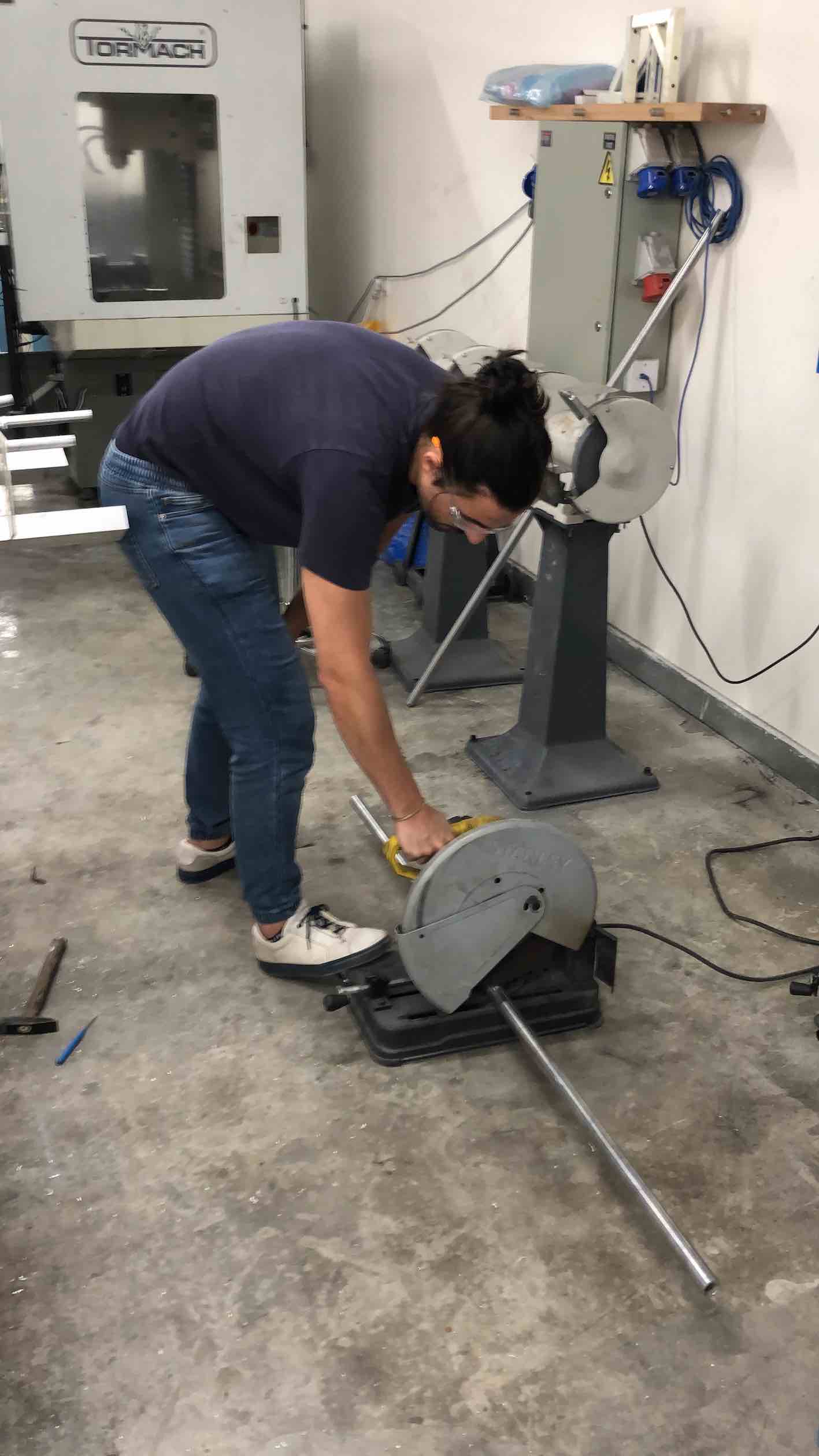
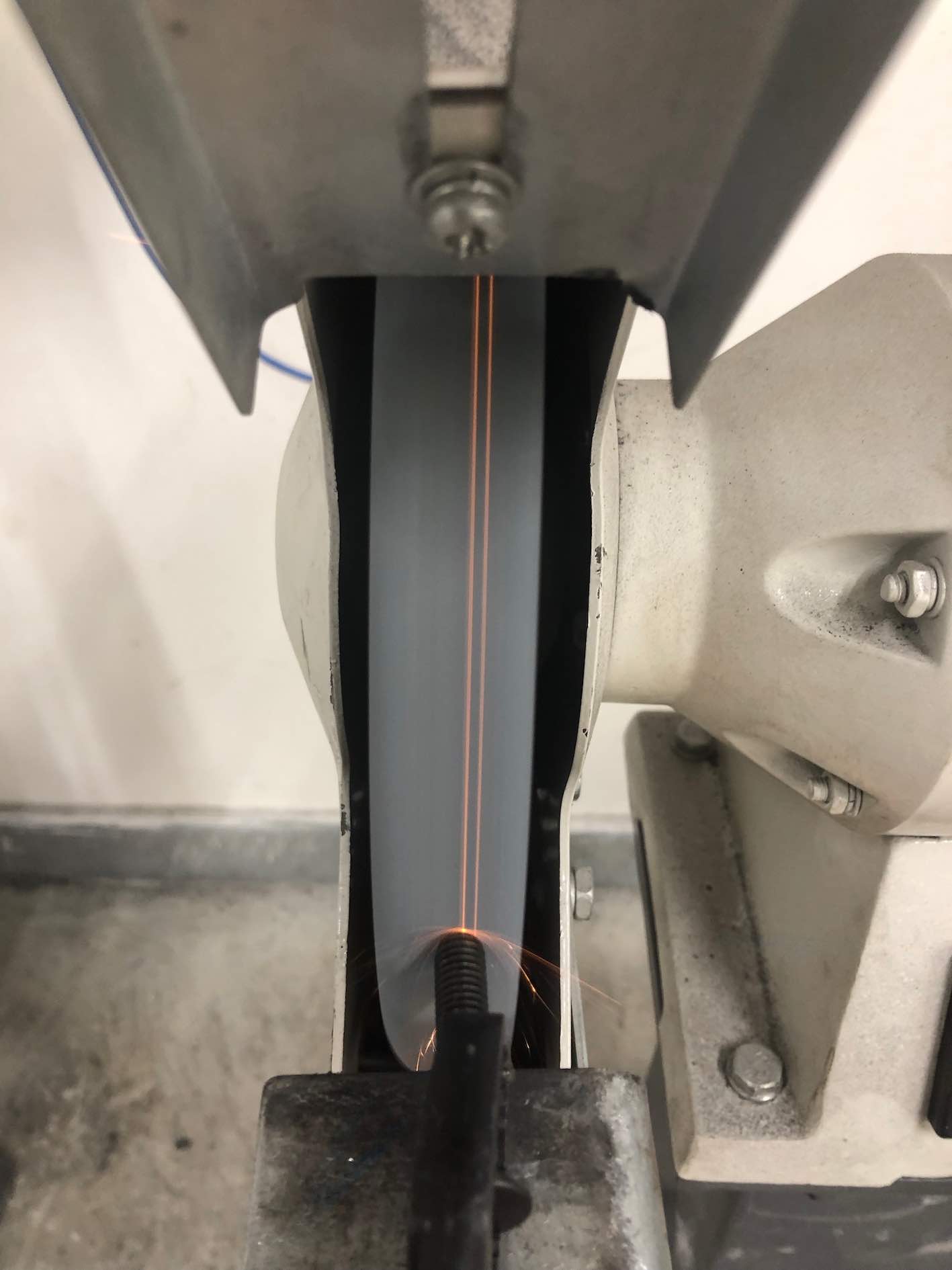
Then I cut the tubes to the desired lengths, using a belt saw for the fiber and an alumunum saw for the aluminum tubes. Since cutting aluminum leaves some extra slag at the cut edge I used the sanding wheel to chamfer the edges to a smooth angled surface.
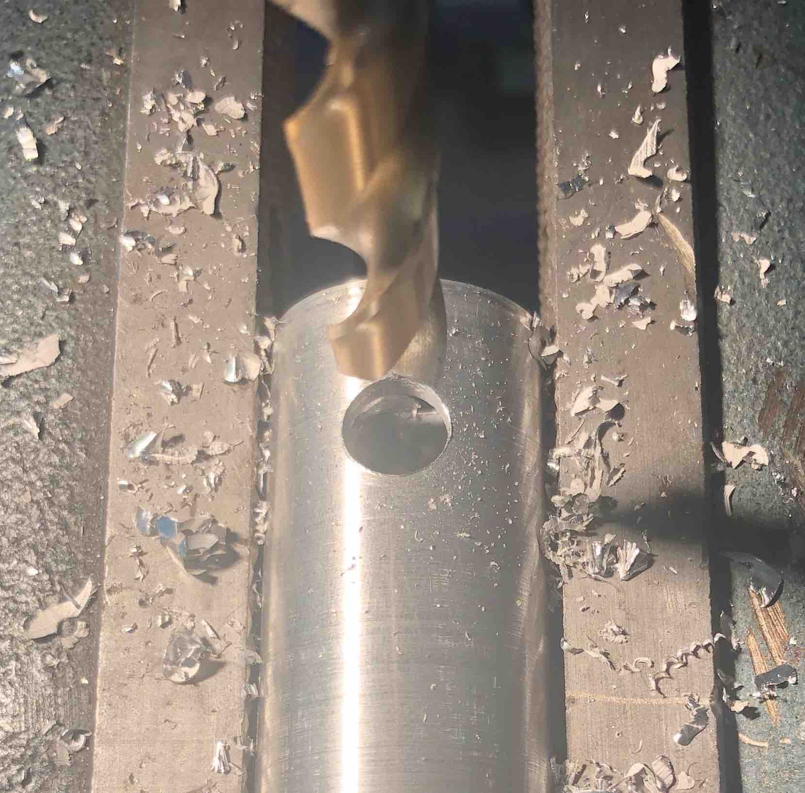
The middle tubes were drilled and pin spring parts were inserted to lock into their joints
Joints
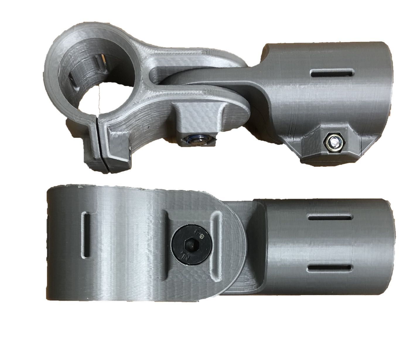
As mentioned before the joints were inspired from 3D printed bike joints and adjustable PVC joints. Depending on the location of the joint there were several different designs used. I also used two different materials, being mettalic PLA and carbon fiber PLA to achieve stronger joints.
Many of the joints were fixed using perpendicular screws or a tangent tightening mechanism.
Handle inspiration, ideation and design
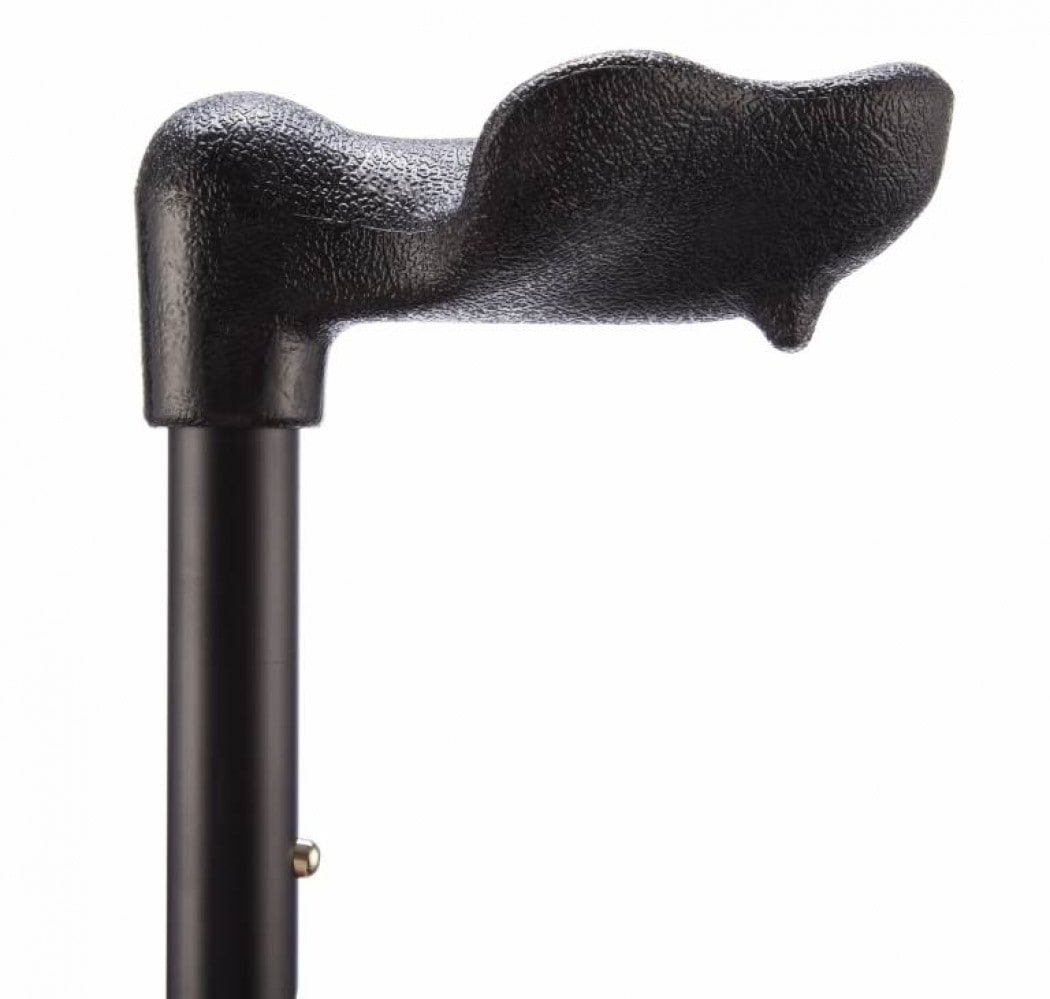
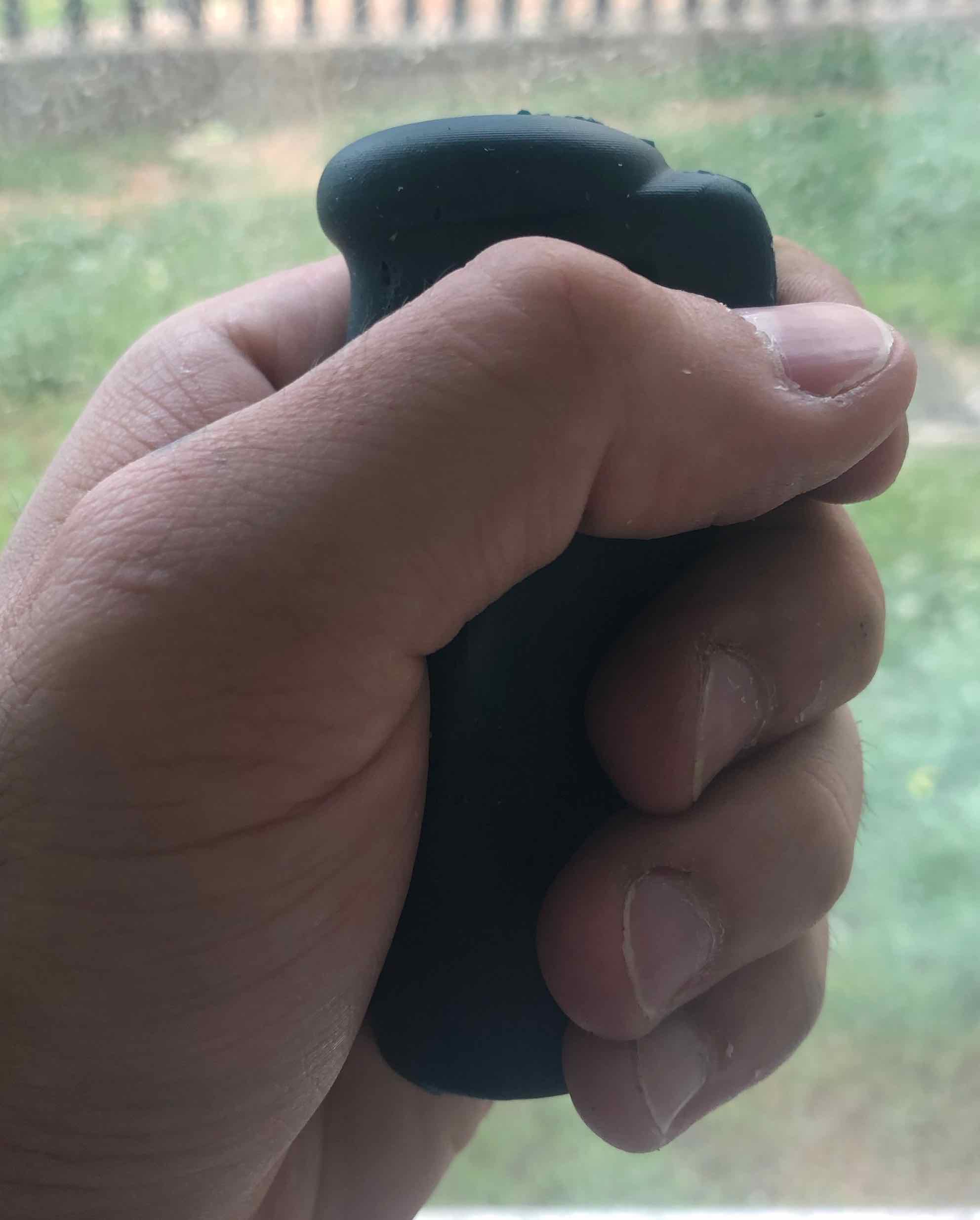
In order to achieve the optimal biomechanic goals, I had to overthink and overengineer every part, including the handle. Since 49.6 percent of people over 65 years have been diagnosed with arthritis, I believe it is integral to tackle this aspect within the handle grips. I was inspired by the grip on this walking cane shown on the right. The grip was designed in an ergonomical point of view to make it easier for arthritis patients to hold it.
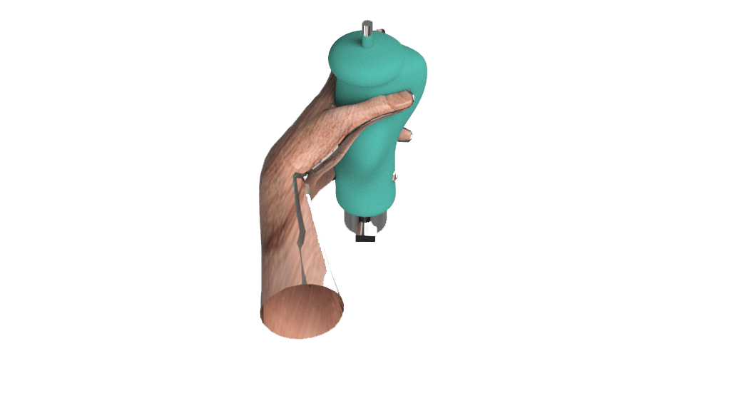
The parameters of the handle where roughly based on this study on ergonomic grips for hammers as well as digitally sculpting the surface according to an imported model of a half clenched hand, to achieve the best topology.
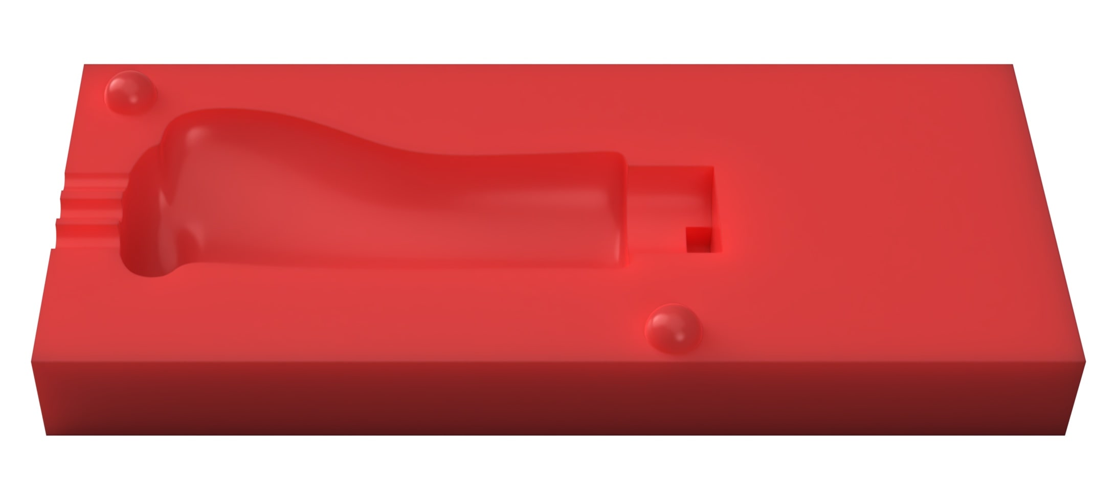
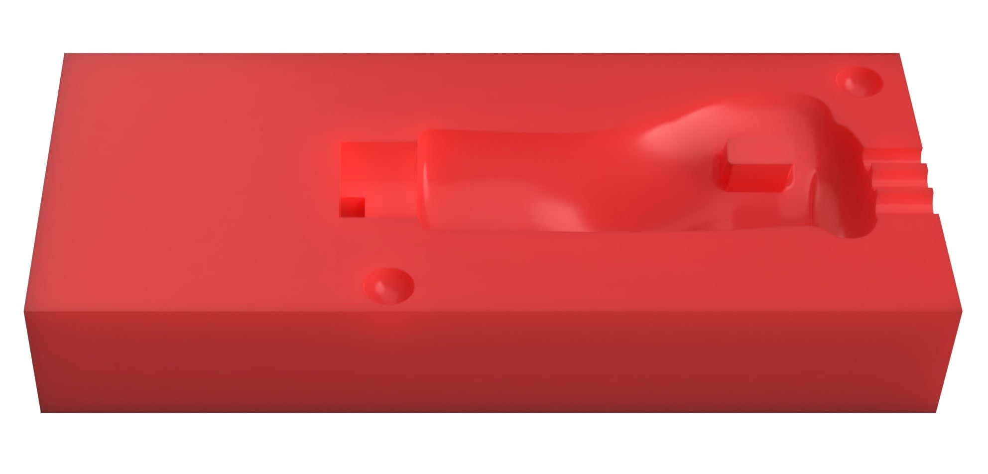
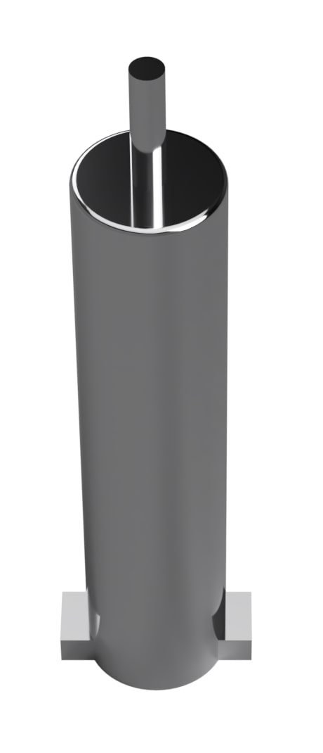
Then I created a box around the model equal to two blocks of wax and subtracted the model from the box. I also created an extrusion which extends to the aluminum extrusion in the middle. The aluminum extrusion is represented by a 3D printed piece of plastic that has two extrusions at the bottom and a thin pole extruded from the top to ensure correct placement within the molds once the silicone is cast.
Top mold
Bottom mold
Aluminium shaft
Handle molding
I milled each side using a different CAM program for the sake of learning and comparing between both workflows. For the first mold I used Modela and for the second I used Roland's SRP player. In both workflows, I used a 1/8 inch flat endmill for the roughing process and a 1/16 ballnose endmill for the finishing process. In both cases I zeroed the Z-axis by placing 1mm paper under the mill and slowly wend down. Once there was resistance when moving the paper, I took the Z-axis 1mm downwards and set the home. As for the X and Y axis, I drew an X from the corners of the wax block and centered the endmill at the cross-section of both lines.
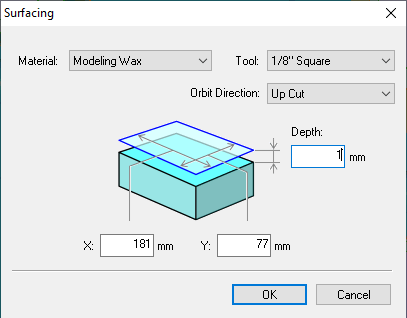
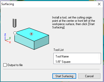
For the SRP player workflow, I initially started by sending a surfacing job. This was simply done by selecting surfacing from the tools menu. I input the dimensions of the block then in the next screen of the wizard selected the XY home in the middle.
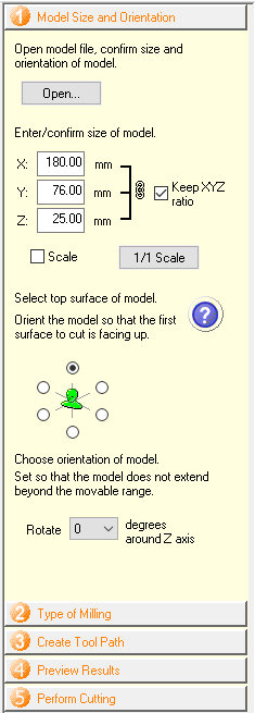
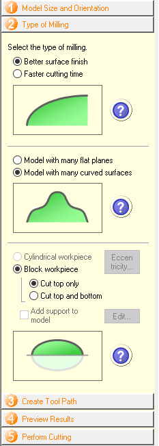
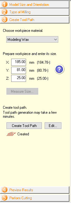
Before setting up the toolpaths, I must first import the model by locating it from the open button. Afterwards setting the dimensions of the wax block, orientation of the model and XY home position. Then the next step is to specify the type of milling and edges in the model. As is obvious, this program is quite automated and doesn't allow much personalization at first. The next step before simulation would be creating the toolpath.
Size and orientation
Milling specification
Toolpath creation
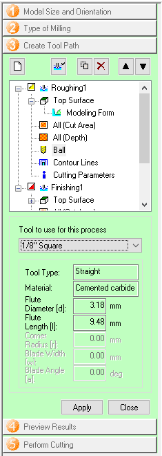
Although the toolpath is automatically created, one has the option to go through the edit menu and change certain parameters. As seen in the screenshot on the right, the roughing and finishing toolpaths are shown seperately with the parameters and properties of each. In my case, I changed the tools to the 1/8 flat and 1/16 ballnose. If anything was changed, remember to create the toolpath once again.
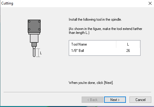
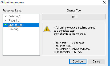
Once all the settings were entered and the toolpath created, I simulated the milling job and inspected the resulting model before going ahead with the actual job. A window will appear once a toolpath is complete to instruct you to change the tool, if required.
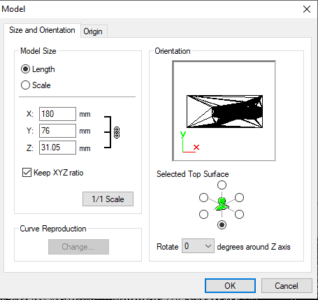
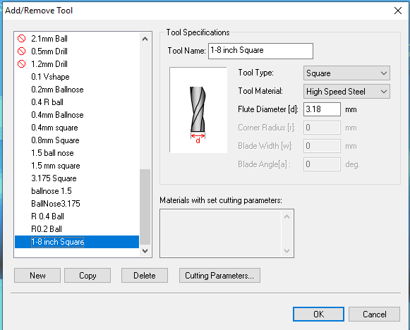
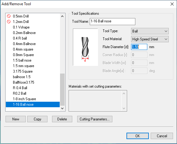
For Modela, I imported the model and input the correct size and orientation in the pop-up window that appears. Then I had to introduce the tools I will be using as they weren't available available in the tool library. Luckily, this was easy as after inputing the flute diameter, Modela can automatically generate suitable cutting parameters.
Import model window
1/8 flat tool
1/16 flat tool
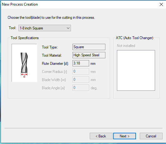
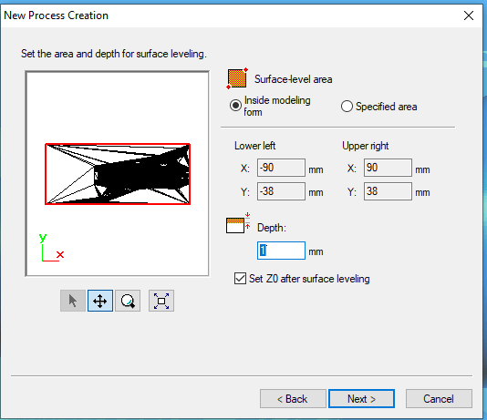
As opposed to SRP player's user-friendly path creation, modela requires the creation of each path seperately. This means increased control over the job and how the model is milled. The first toolpath would be the surfacing toolpath, so after creating a new toolpath, I was guided through a wizard. I selected surfacing, then selected the tool I will be using, then specified the paramaters and depth of the surface leveling, 1mm in this case.
Toolpath creation
Tool selection
Surfacing depth
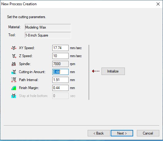
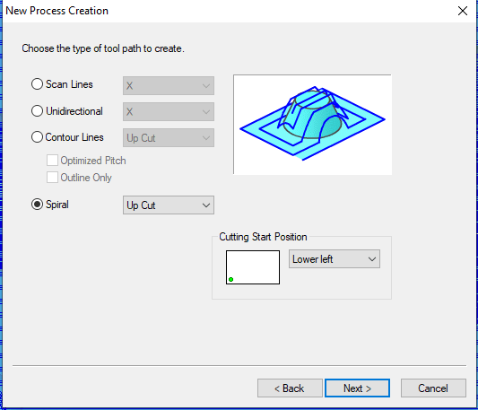
For the roughing and finishing jobs, the wizard is pretty much the same, however the settings differ. I left in 0.44mm when roughing, to be removed in the finishing jobe. Also to achieve a better finish for the curved surfaces in 3D, I chose the spiral upcut toolpath.
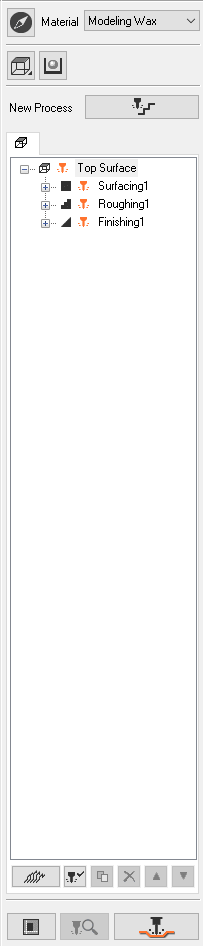
Once all toolpaths were created, they can all be viewed and edited from the window on the right. The next step after checking the toolpath parameters is to simulate the model CAM and then output the file. Note: This is also the side window from which new toolpaths are created and the model is output.
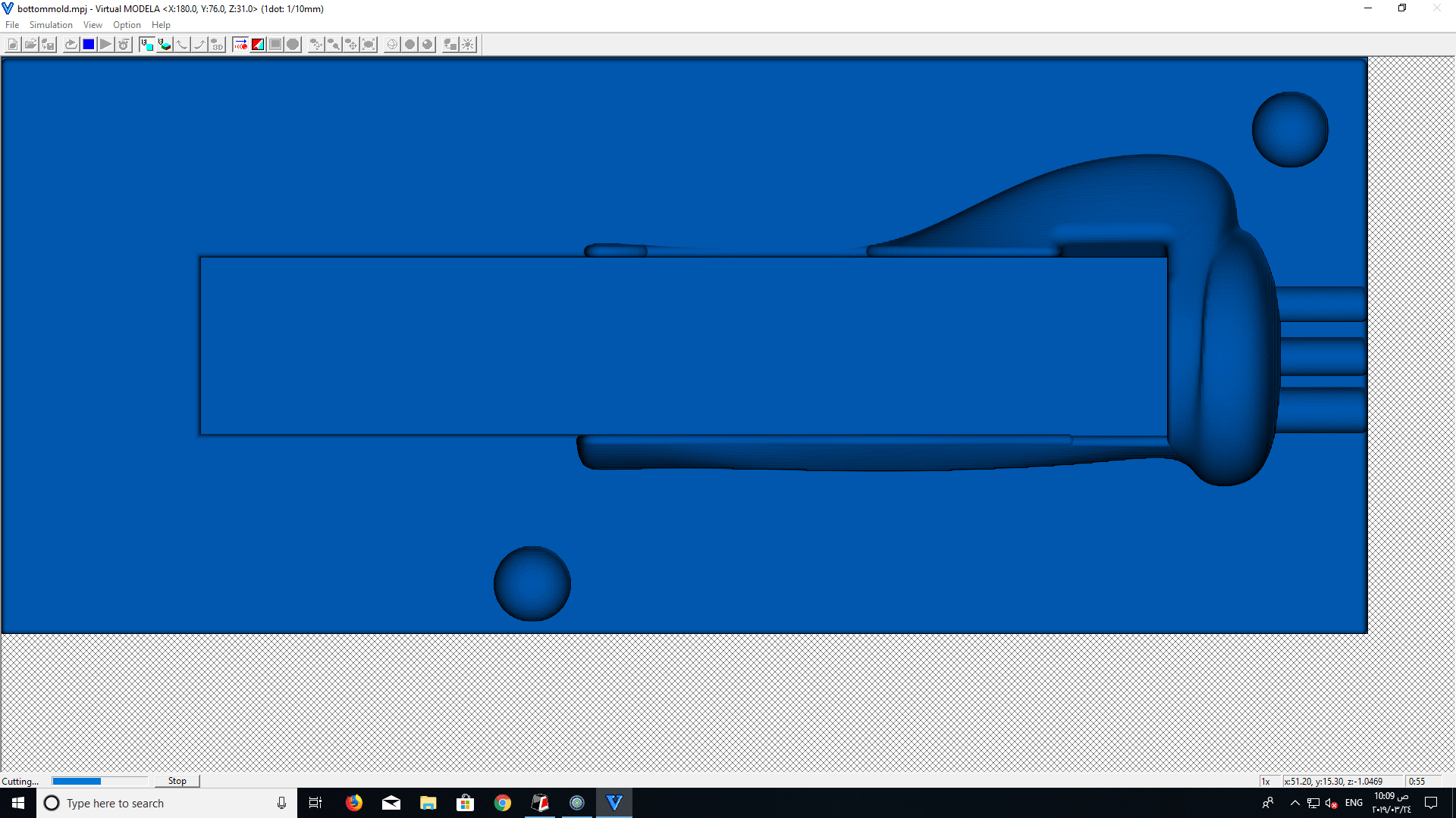
I ran the simulation and the model shown on the left looked like everything was okay and ready to be output to the milling machine.
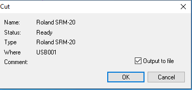
To output the file, choose the SRM-20. The progress window will indicate the progress of the job and instruct you to change the tool once a tool change is required.
Output to machine
Change tool (progress window)
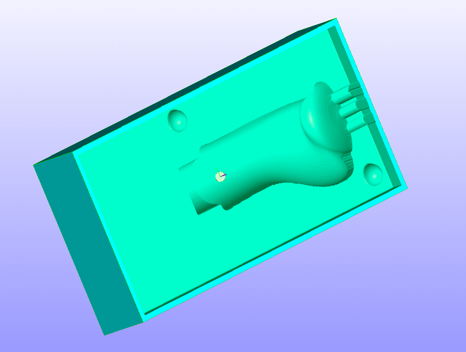
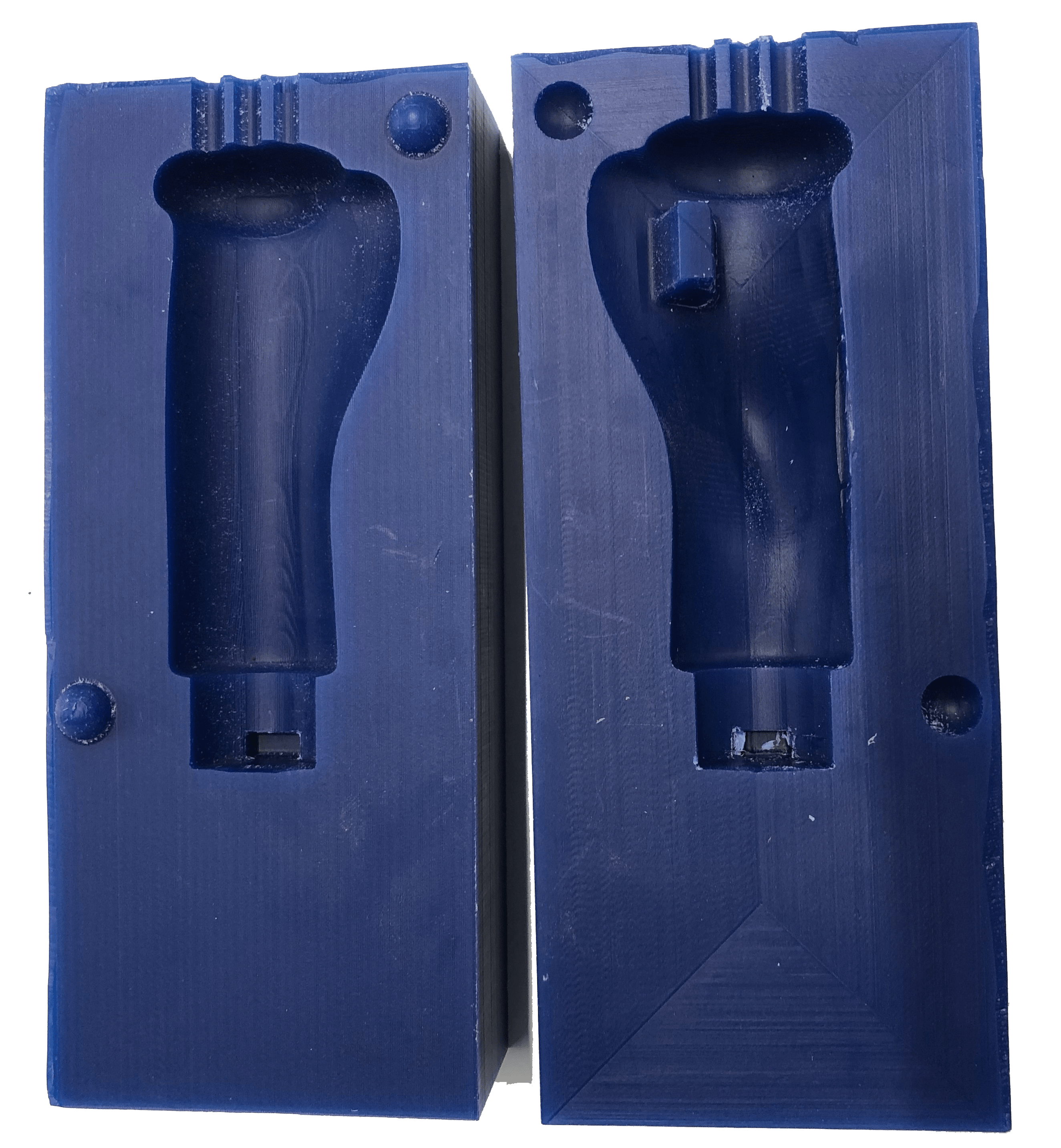
Below is a picture of the resulting wax molds.
For the other handle, I simply mirrored the molds and model, then scaling up the outer surface to illustrate the modularity of the design and its ability to be custom made depending on the patients physiological dimensions.
Since when doing the first wax mold, I found Modela to render a better result, I stuck with it and tried to achieve an even better quality. I dug within the settings and discovered the step-over and step-down parameters are identified as cutting-in ammount and path interval.
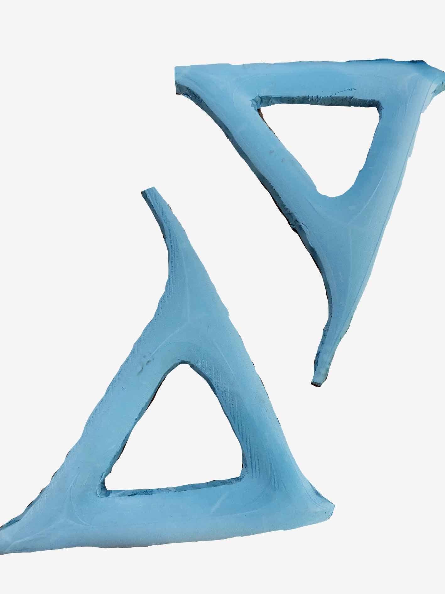
Handle casting
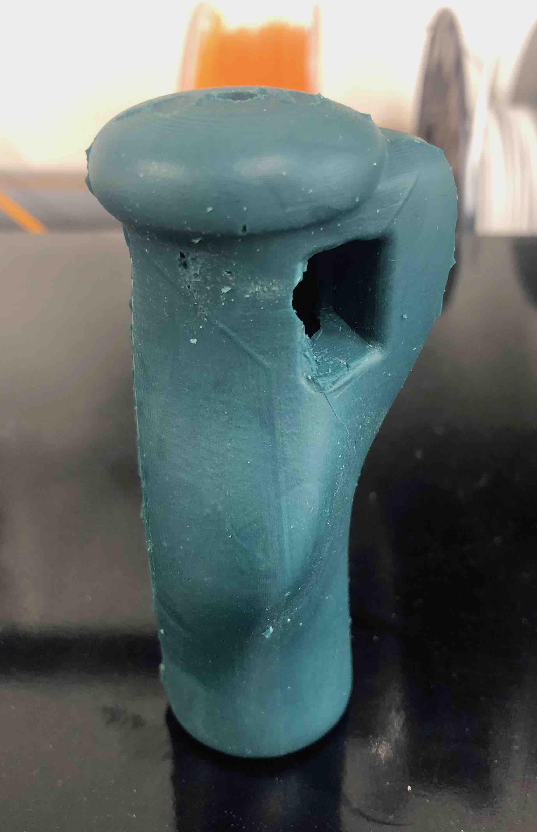
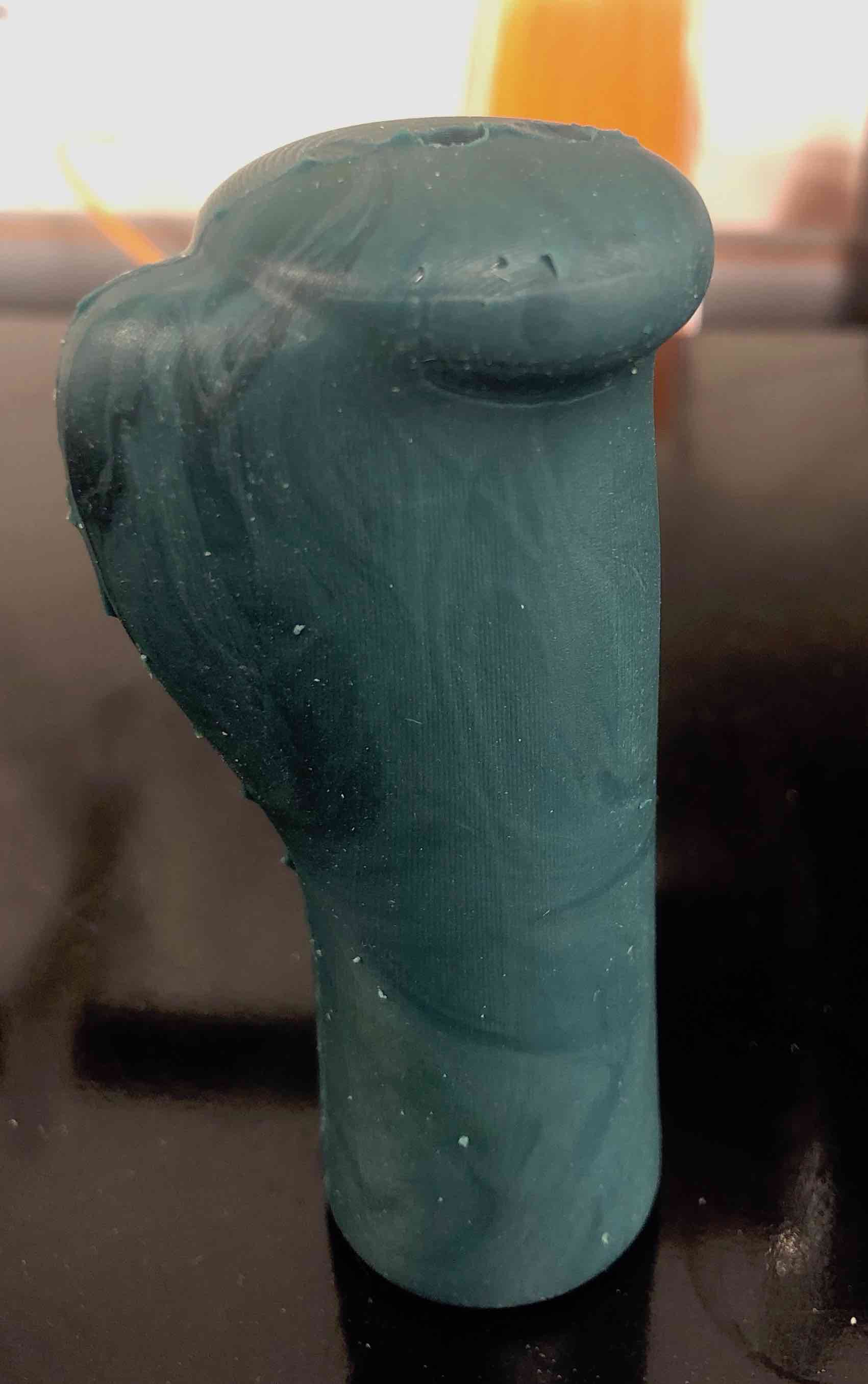
Before mixing the MoldStar 30 silicon elastomer material, I did some research and refered to the , in order to check the pot time and cure time for the material, in addition to the mixing volumes and preferred temperature. So with a 45 minute pot life and a 6 hour curing time, I mixed together a volume of 1:1 of A and B, and poured it into the milled wax molds. I then pressed the molds against eachother and sealed them flush using one-handed bar clamps. 6 hours later, I pulled the molds apart and removed the model. Finally, I removed the excess silicon at the seam line using a box cutter.
The cast of the handle presented above was fine in terms of shape, but didn't meet the colour requirements I was aiming for. I therefore repeated the process, using a different ratio of dyes (yellow and white), keeping track of the exact amount I used. I acheived the desired colour by adding two drops of yellow and two of white to a full plastic cup of Moldstar 30 silicone. I should mention that I mixed it with the blue colored part before mixing together parts A and B of the silicone material. To the right is the first handle casted and below are the left and right handles, notice the same colour, with the HR and pulse oximetry sensor attached.
Wheel inspiration, ideation and design
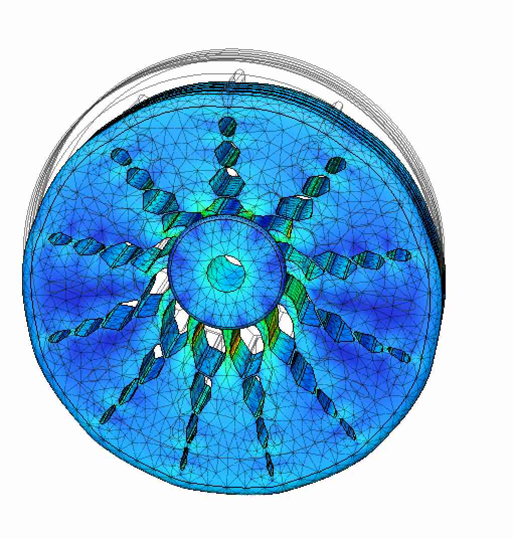
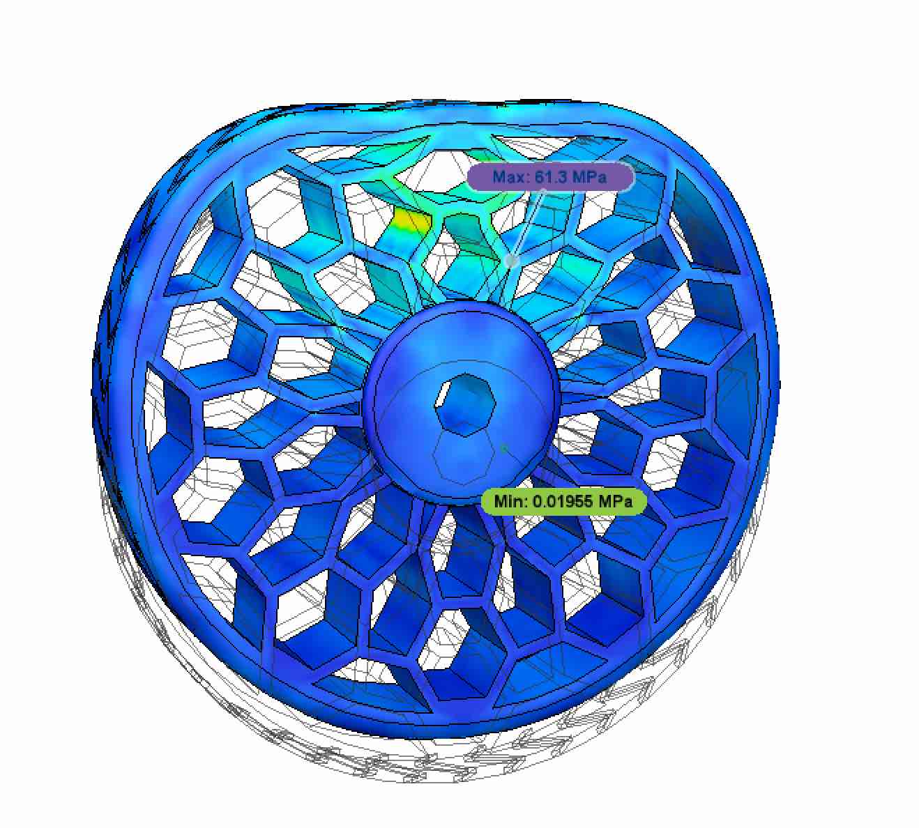
I've started designing the wheels since they probably wont change throughout the development of the project. The wheels are modeled for all terrains and are supposed to make going up and down a step easier. The inspiration for this design and detailed sketches/dimension can be found . I modeled a first prototype which involved geometric and parametric designs, extrutions of profiles, revolves and circular patterns. After running a simple simulation, it seemed like much of the stress is focused on the axel. This was probably because the cuts in the wheel body were denser around the axis than near the wheel's circumfurence.
After performing the simulation, I flipped the polygon pattern to decrease in size as it gets closer to the axel. This allowed me to produce a much lighter model with better force dissipation and less stress concentrated at the axel. I performed a simulation with double the force and the result was closer to what I was aiming for.
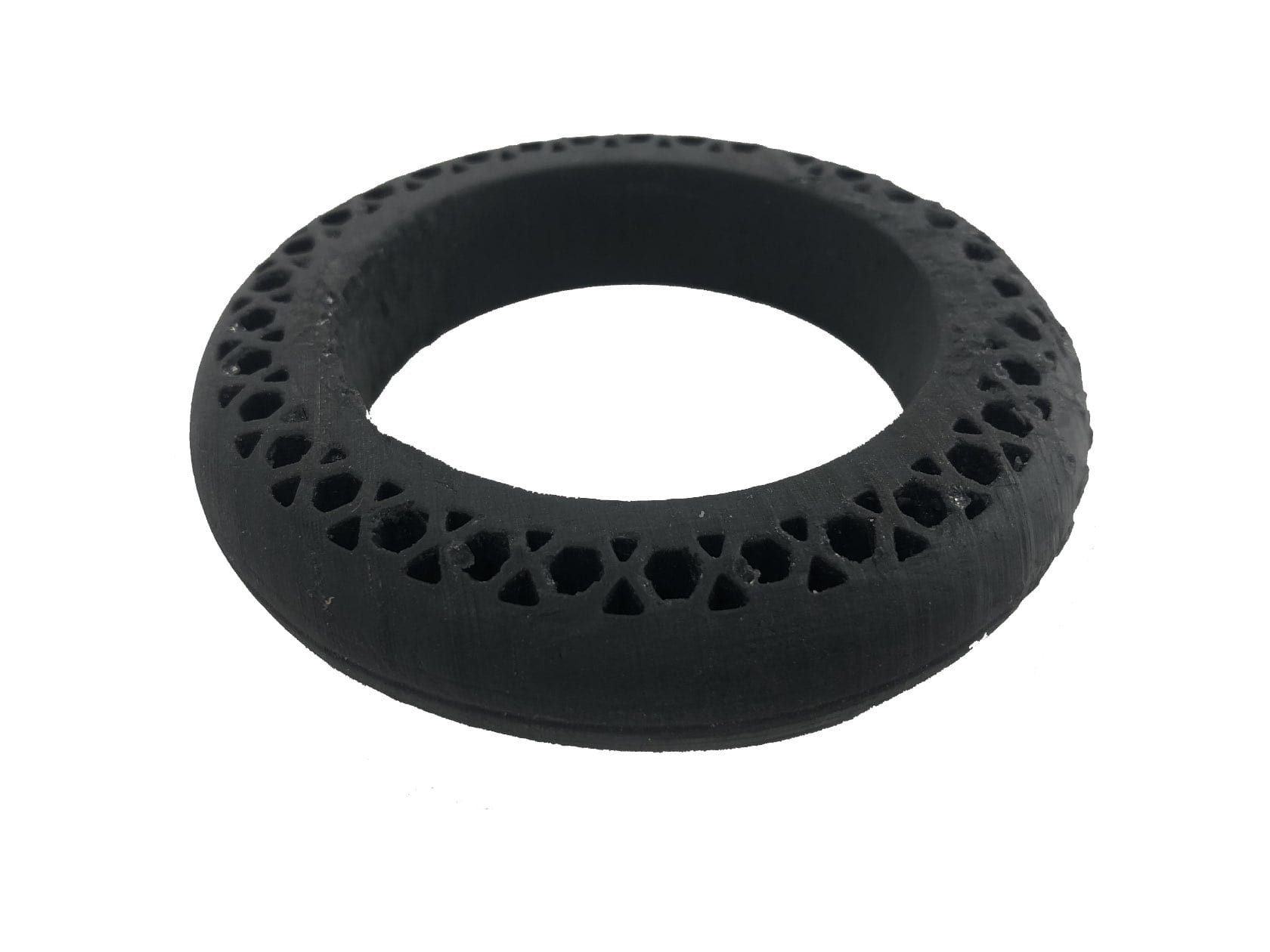
For the back wheels I used the same concept but with less flexion since the patient will be applying more load to the back of the walker and I want to ensure better stability. It was acheived similarly to the front wheel using extrusions of the wheel's profiles, circular patterns to repeat extrusion patterns and fillets to curve the corners. Revolute was used to crate wheel traction patterns.
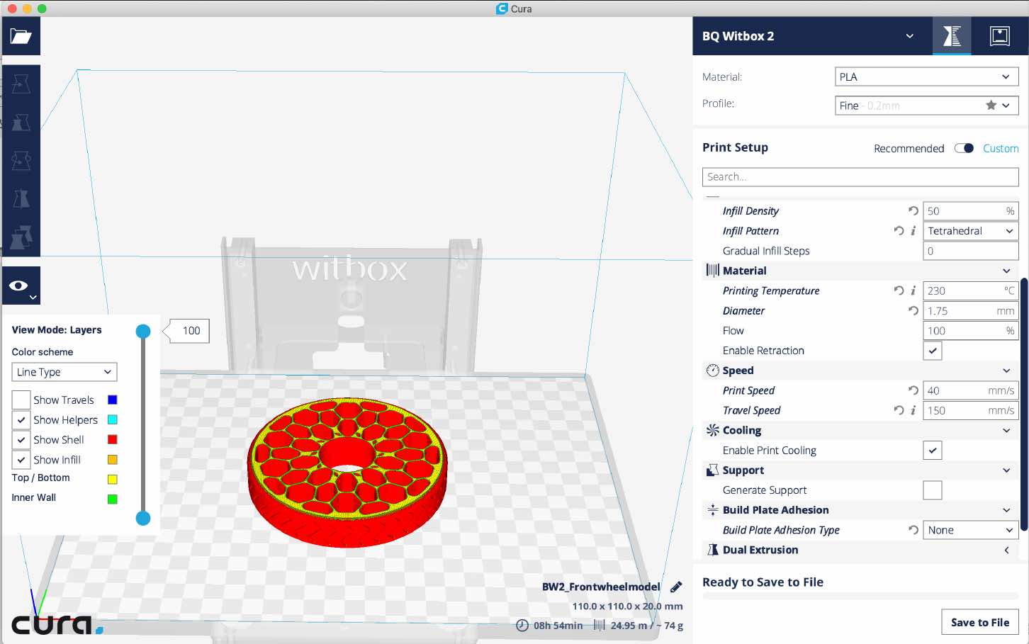
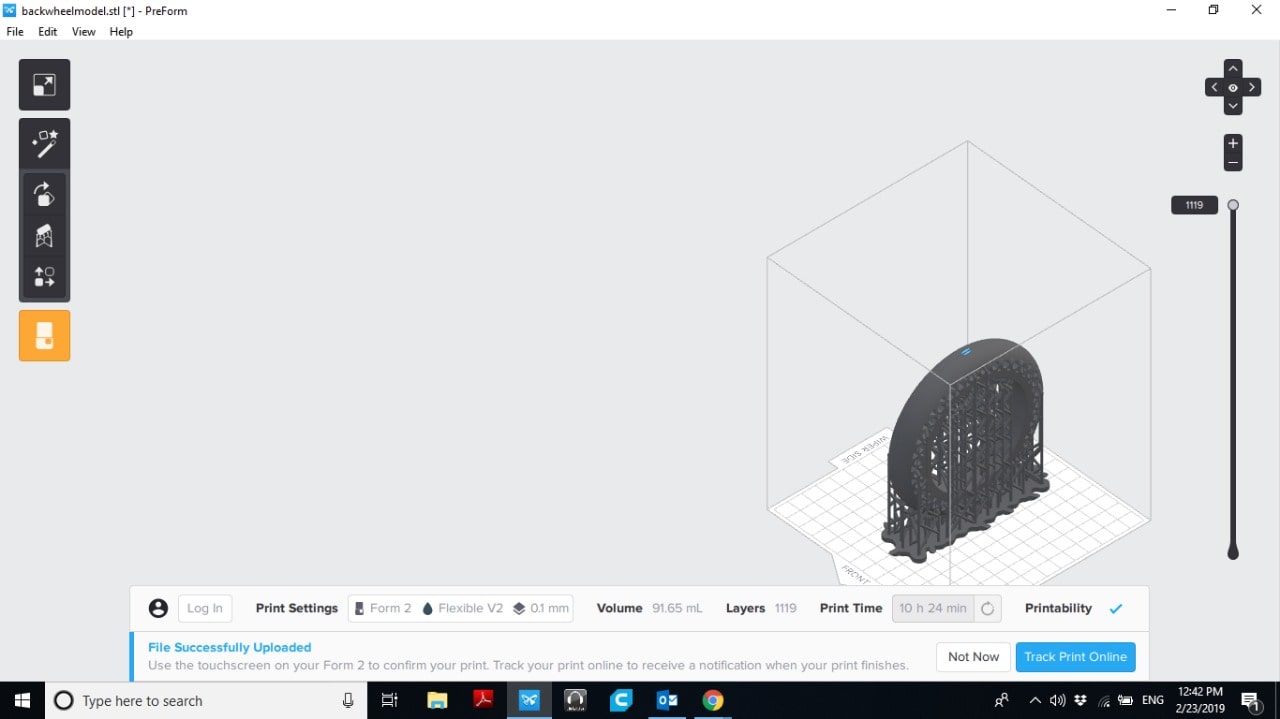
The wheels, both designed during the CAD week , consist of mesh structures to distribute the stress amongst the model. The back wheel is designed to be less flexible as it will be supporting most of the weight applied by the user. Therefore, it will be manufactured using flexible resin on the Form 2 SLA printer. The material is similar to rubber used on wheelchair wheels and suits this application. The front wheels however need to be more flexible to avoid getting stick on rough terrains. We had two flexible materials for the FDM printer, ninja flex and filaflex. After surveying a few of the prints done with each of the materials. I opted for ninja flex as it’s stronger and not too flexible that it will collapse once a force is applied. It is important to note, that due to the filaments diameter, 1.75mm, the model was produced using a Witbox 2 instead of the Ultimaker 2+
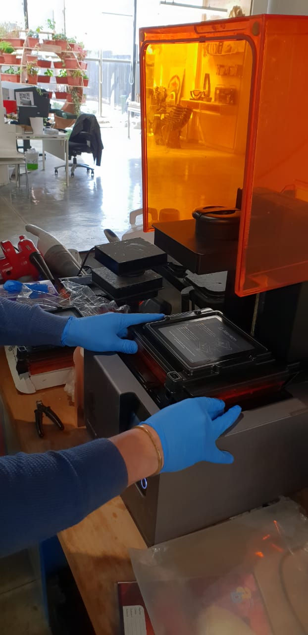
To commence with the print I put in a new tray and print bed for the flexible material, as well as putting in a container of flexible resin. I then went on and started the print job
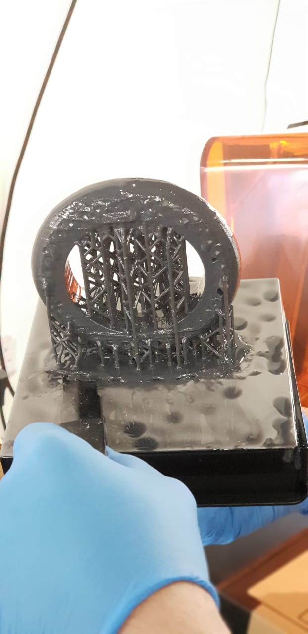
A good 9 hours later, the job was done and the model had to be soaked in ethanol to remove any extra resin off the model. I soaked it for approx. 5 mins.
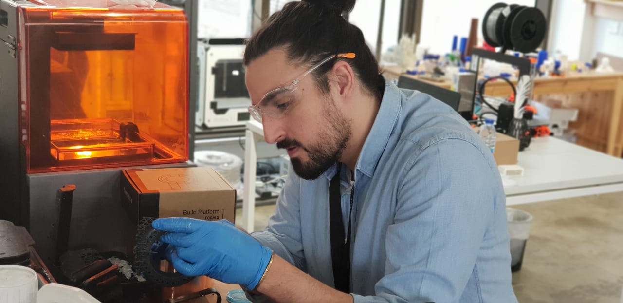
Finally I did some post-processing removing all the support structures in order to cure the model.
The following are pictures of each resulting model. While, the SLA print was up to standard, the Ninjaflex FDM print had morphed at some point causing an uneven surface. I believe this might have been caused by the lack of a heated bed on the Witbox 2. I decided since I was going to print the other sides, I would use the same settings for the SLA back wheel and switch to another flexible material to be printed on the Ultimaker 2+. This would also mean I would be printing 2 new front wheels.
The new front wheel was printed with the following settings at a temperature of 225 degrees celcius. It is very important to not that when printing flexible filament on a bowden mechanism extruder, the speed has to be slowed down to avoid stretching of the filament and problems with printing. I printed the model at a speed of 20% for the first few layers and then sped it up to 30%.
Oxygen holder inspiration, ideation and design
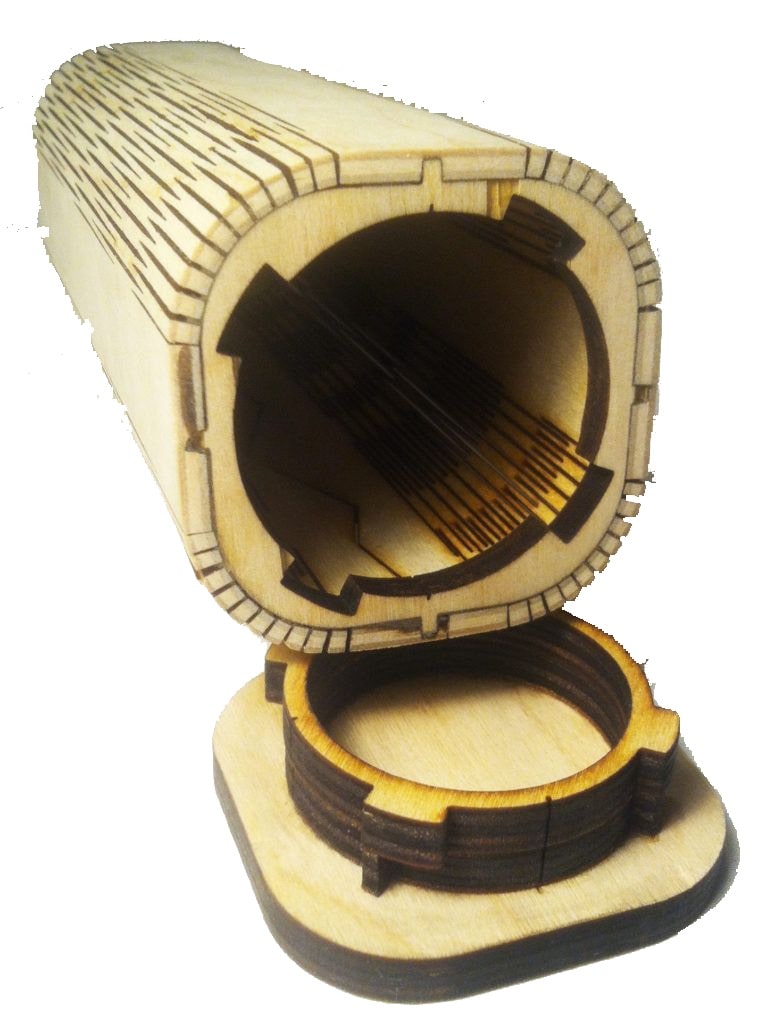
The only laser-cut component is the oxygen tank holder, which due to mainly aesthetic reasons, I will be fabricating out of acrylic. For a stronger body, I chose 5mm thick acrylic. I found an example of a wine bottle case that used a very interesting approach using wood kerfing. So I decided to use a similar approach that has been achieved but using acrylic instead of wood.
I was granted beta access on a new laser-cutting web application called KYUB. It was mentioned during one of our lectures, after which I applied for the beta access. KYUB is optimized for laser cutting design simplifying the construction of bent corners, cutouts and integrating kerf and material width. I initially started with a long design as with the example mentioned above, and then moved to a simpler design composed of two pieces. The bottom, a base to hold the oxygen canister and a top lasercut piece, sliced using slicer for fusion, to hold the top using a fabricated belt.
KYUB includes a very cool feature, which is a Kerf measuring design. I cut it using the 5mm material, and chose a tight fit for the kerf. After cutting the rest of the model, I realised that this was a bad idea, since with so many components all fitting together, it was too tight of a fit... this caused some components to snap when I tried putting them together. Also, the very narrow curved pieces snapped as soon as I tried bending them. So, I went back to the drawing board to review my design and try again.
Outer body inspiration, ideation and design
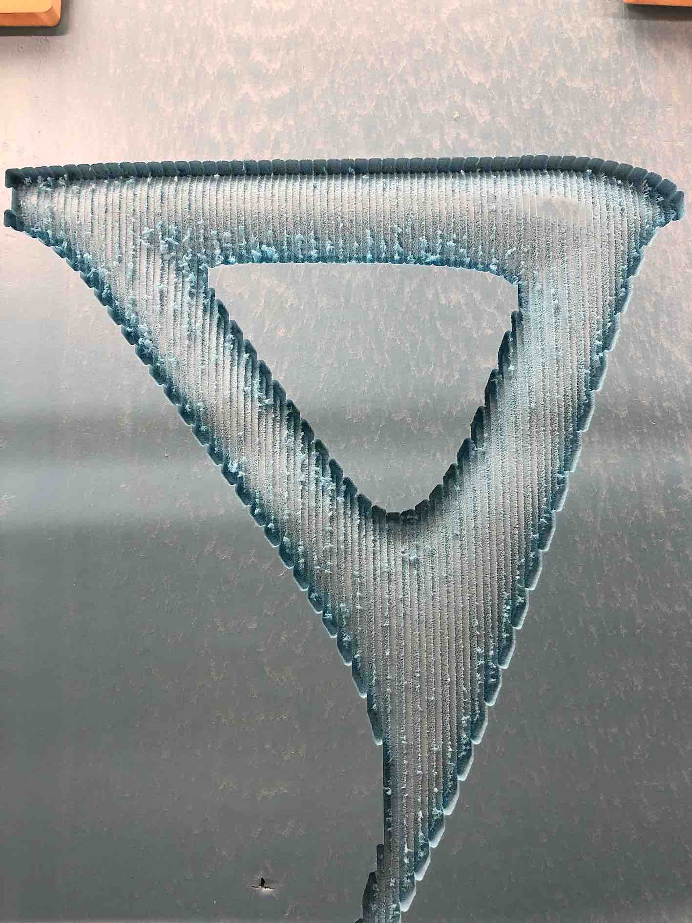
The design inspiration for the outerbody was mainly from more advanced mobility vehichles and wanted to achieve a sleek aerodynamic look to a certain extent. It was also a chance for me to try working with both foam and fiberglass.
Foam mold milling
The foam was extracted as an stl and input into shopbot's program Vcarve. I then followed the wizard and chose the correct settings. For foam I had to decrease the spindle speed to 10000 RPM and ensure the suction is working correctly to avoid melting of the foam. I made some quick fixing brackets using scrap wood since a nailgun wont work with foam.
The foam was milled using a 1/4 flat endmill for roughing and a 1/8 ballnose for finishing.
The next step was protecting the foam. I didn't have any acrylic coating, so I resorted to covering it with vinyl all over. The first picture to the right shows the result of using oil based products on foam. Once the foam was fully sealed, it was ready to have the fiberglass shaped around it.
Fiberglass body fabrication
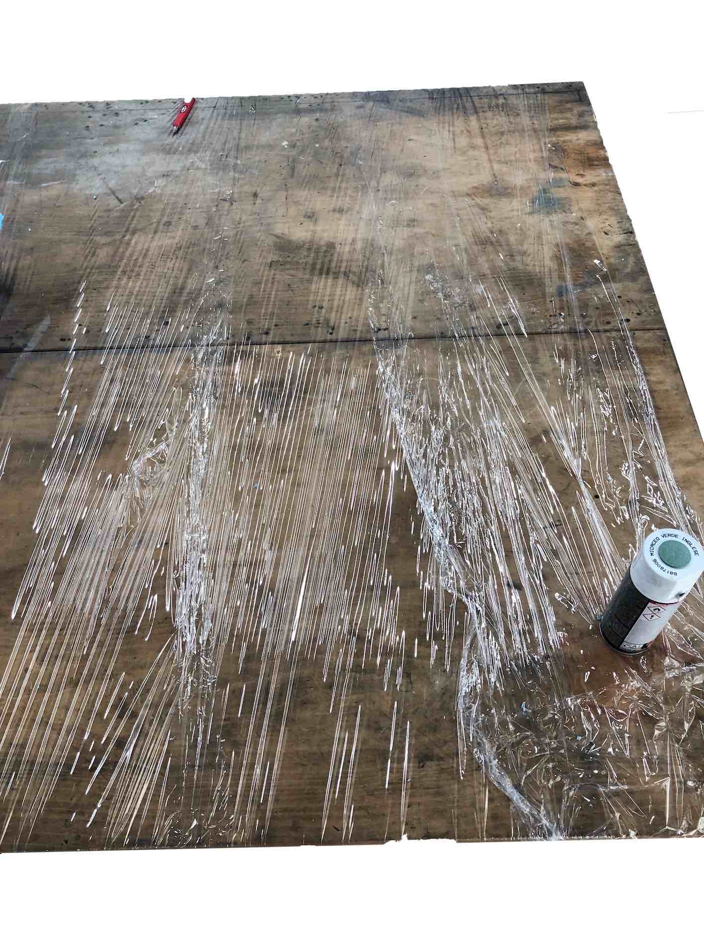
I used our metal shop for this process, as it had the best ventilation and a large enough work area. I wrapped the worktable with several layers of nylon wrap to protect the surface from any resin or paint. I had the window open and the fume hood on to ensure all the workspace was well ventilated.
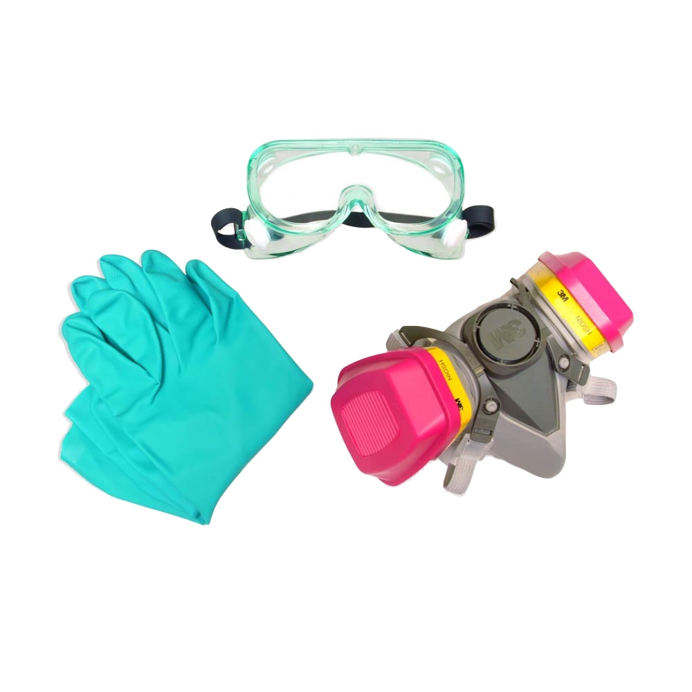
I also wore PPE such as a mask, gloves, saftey glasses and an apron to protect any uncovered skin, my eyes and lungs as well as my clothes.
I used a local resin to harden the fiber, both which I obtained from a car body repair shop. Unfortunately, there was no datasheet provided, and I was told it is mixed by using one bottle of hardener with every gallon of resin. Calculating the ammount by weighing both the hardner and resin, I arrived at a ratio of ~350:1 resin to hardner.
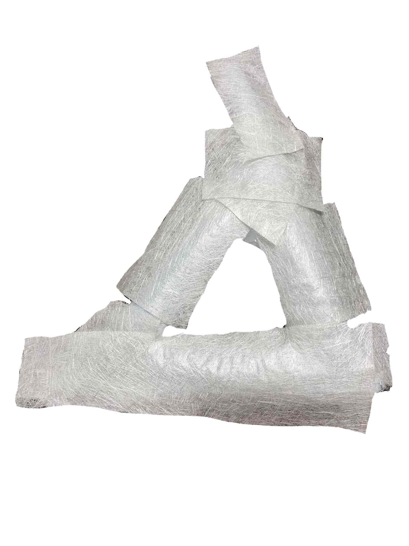
I cut up patches of raw glass fiber material and made sure I had enough, I mixed the local resin using a ratio of 350 to 1 resin to hardner.
When applying the resin to the fiber material, a blotching or dabbing movement is better than a painting one to ensure the resin is absorbed well .
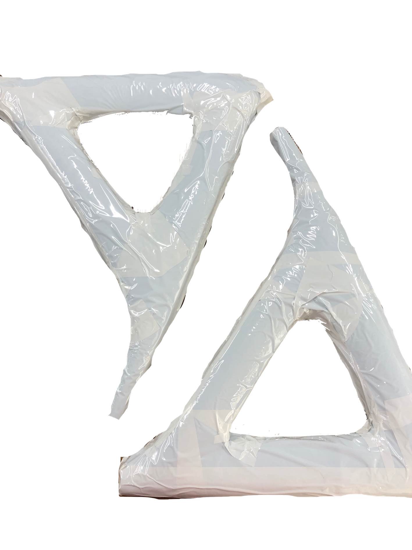
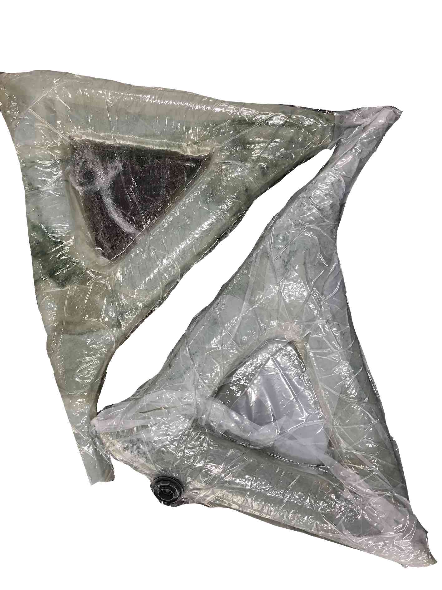
Once the resin has been applied to the fiber material, I covered the pieces with nylon aprons and put them in vacuum bangs to ensure the fiber takes the shape of the mold. I vacuumed the bag and left them till the next day to harden.
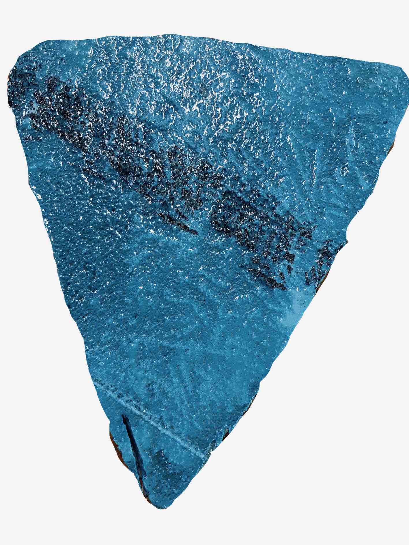
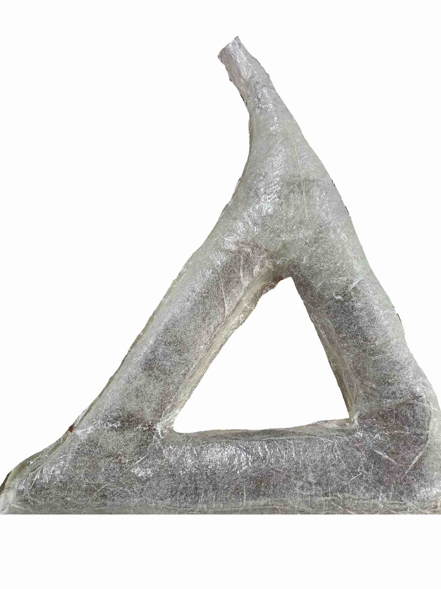
Once the resin was set I moved to the finishing process, it involved a repeating cycle of sanding and priming, increasing the sandpaper grit every cycle. After 3 cycles, I decided I had reached a smooth finish and was ready for the painting process.
I mixed the paint with paint thinner, until I got a milk like consistency. This was required to avoid clogging the airbrush. I poured the thinned paint and sprayed the fibreglass pieces using a steady lateral motion from a distance of about 20-30 cm.
Processing boards
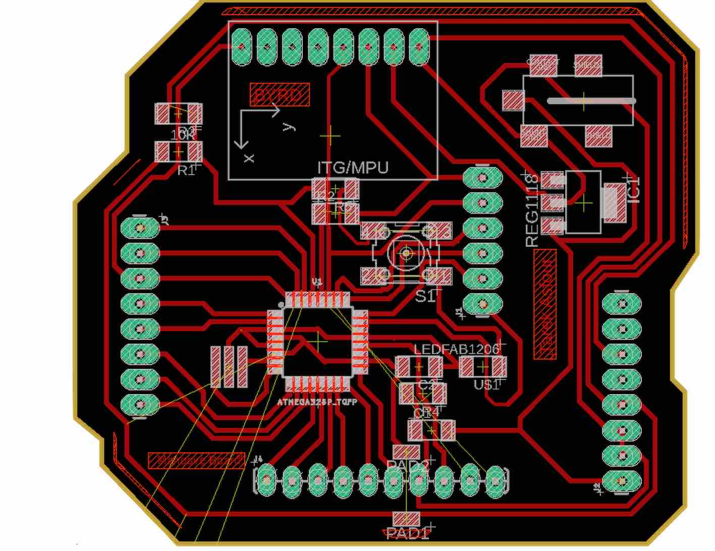
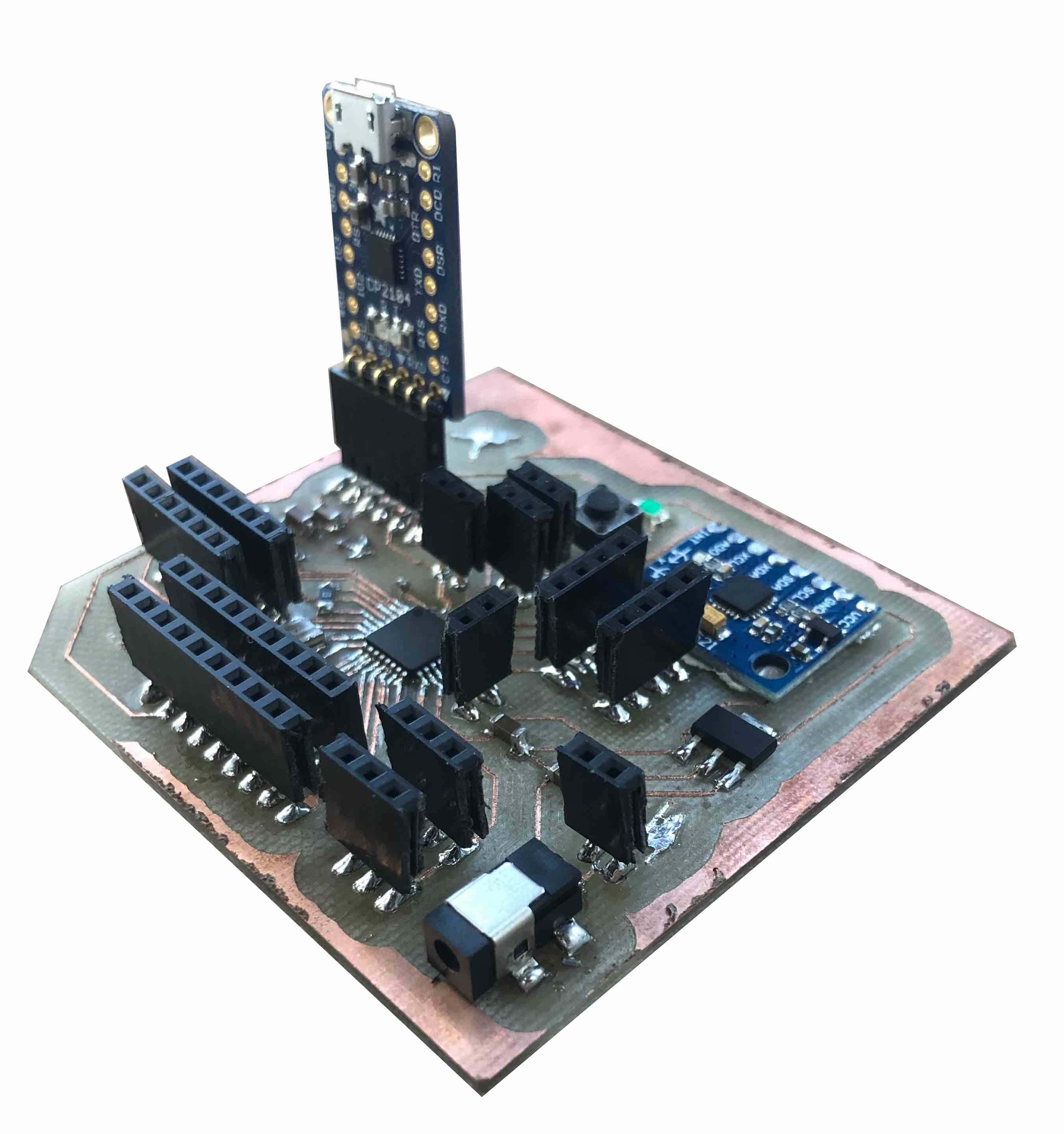
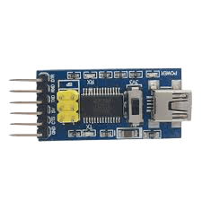
Since the development process I am following is spiral and I'm not sure how much functionality I will have time to include in my final project, I decided to make a modular board. The board I designed is optimal for stacking and testing. In other words, I will be able to manufacture an input and output board that will stack above it once testing is over. The design was inspired by Daniele Ingrassia's , which itself is a fabbable, arduino friendly development of the Fabkit. We didn't have any chips for FTDI to USB conversion, so I used a breakout board we had on hand. Also, I integrated the accelorometer/gyrometer board into the shield. This way the shield contains all the basic requirements, including a build-in sensore, with USB programmable capabilities. At first I used headers to plug in the FTDI shield, which will be removed once the stackable boards are fabricated.
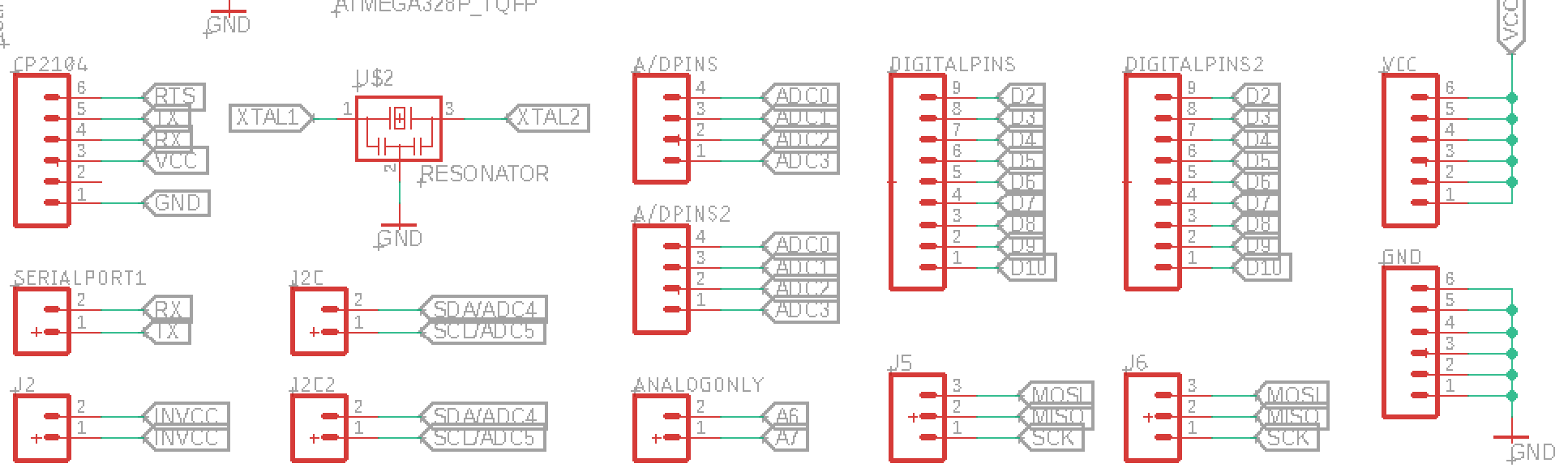
My main goal was to have a minimum of 2 pins for I/O pins including I2C and Serial pins. While including 6 VCC and GND pins. This would allow the connection of atleast 6 sensors or actuators. Ofcourse, if stacking is achieved these numbers can be increased by using I2C to communicate to the sensor and other pins open for outputs and non-i2C inputs.
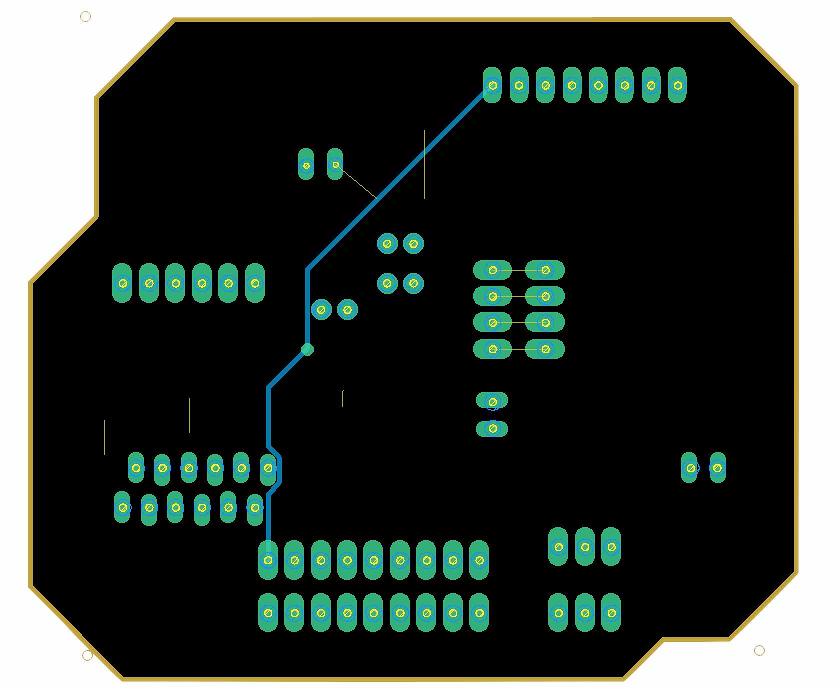
Although I was using a two-sided PCB, I decided to make the design applicable for 1-sided PCBs, this was done by including numerous 0 Ohm resistors as jumpers. However, even after attempting many different routing configurations, There was still one wire that was left unconnected. So I settled on having it connected by an external jumper for one-sided PCBs or using the bottom side on a two-sided PCB.
Routing attempts
Bottom/external jumper track
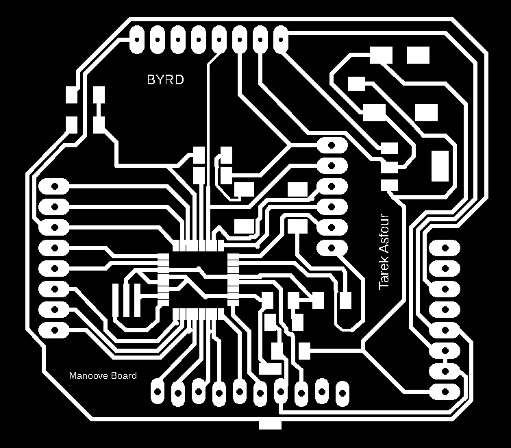
Version 1 board design
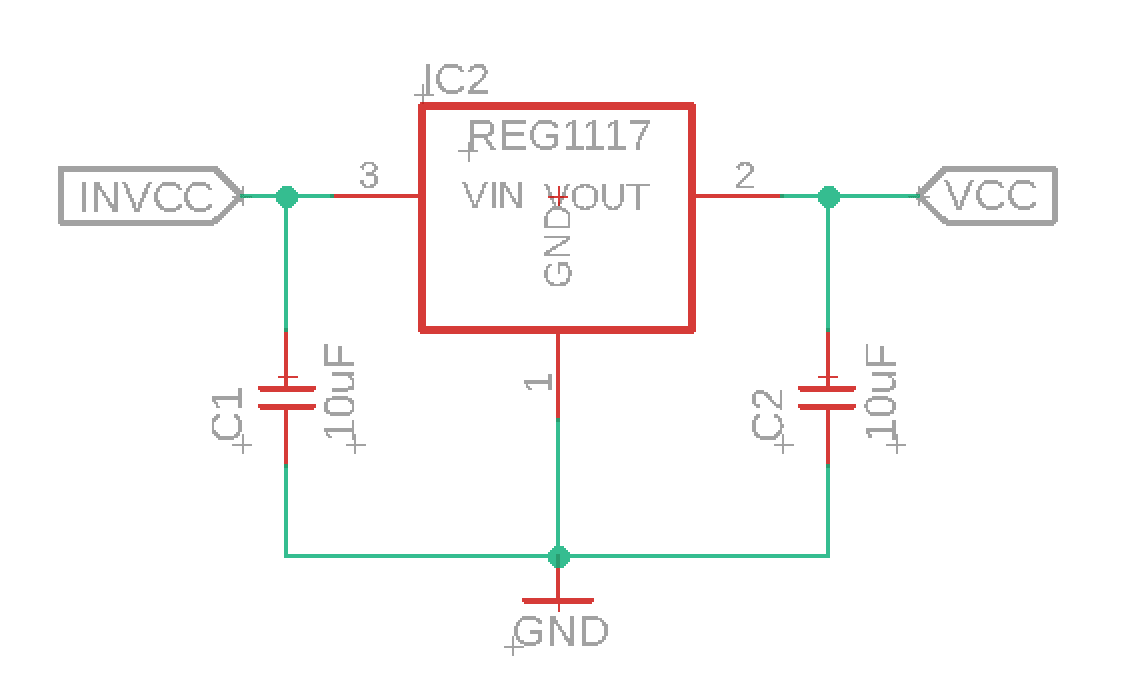
I named my board the Byrduino, and look forward to creating a git page to share the board with other makers around the world. You can see a picture of the first board on the right. Although the board looked fine, it wasn't burning the bootloader, so after hours of testing, I discovered I had used a different type of voltage regulator that is also in a SOT223 footpint however with switched ground and VOut legs. I therefore changed the design to a REG1117 voltage regulator with a SOT223 footpring and decided to integrate another 3.3V regulator to provide a more stable power source for the accelorometer.
My first board also made me aware of another problem, where I forgot to include RST pins required for stackability as well as initially burning the bootloader and programming the chip. I simply added a two pin header connected to the reset track and moved the surrounding components slightly to provide the required space.
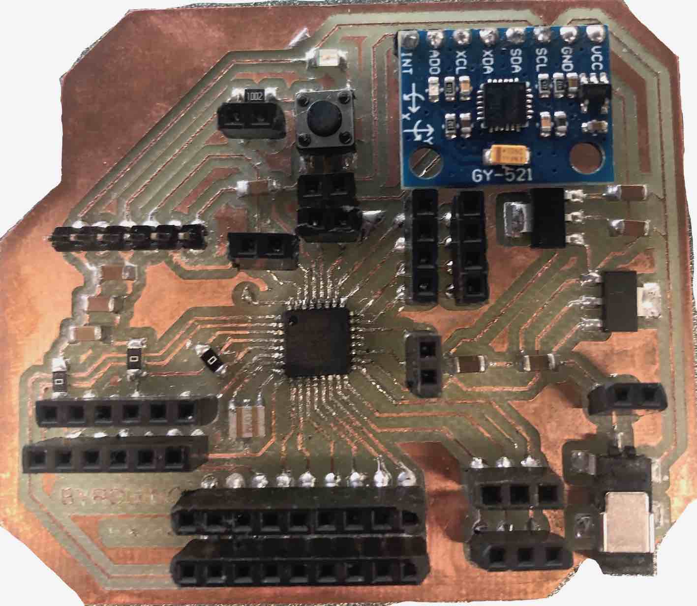
This was the second version of my board design and my first successful byrduino. Some of the tracks look rough, this is because the endmill shipment was delayed in customs and I had to use an overused endmill. However, all tracks were connected well as I checked pin to pin connections using a multimeter.
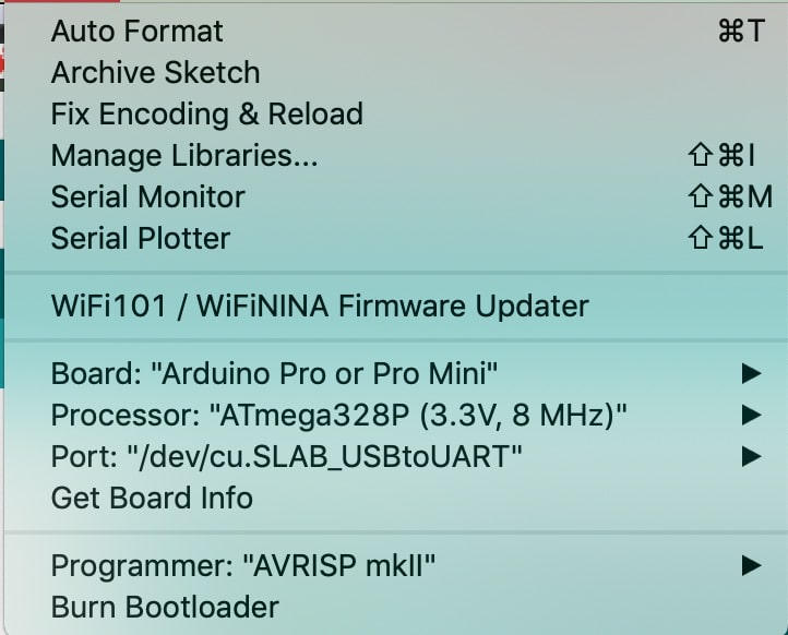
For programming I used the FTDI to USB breakout board and specified the arduino pro on the arduino IDE as it contains the same chip and programs the Atmega328p seamlessly.
Accelorometer/ gyrometer
The accelerometer/gyrometer chip I was using was a tricky chip to get started with from scratch, for someone with no prior experience. I therefore decided to start with the example and develop the example code to fit my requirements for my final project. I downloaded the and opened the example code. Depending on what you comment and uncomment, the code can provide the values of the gyroscope and accelerometer in different formats and references. I decided to choose the yaw pitch roll format as only the gyrometer values are require for my application.
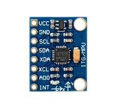
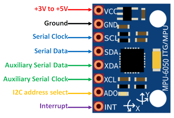
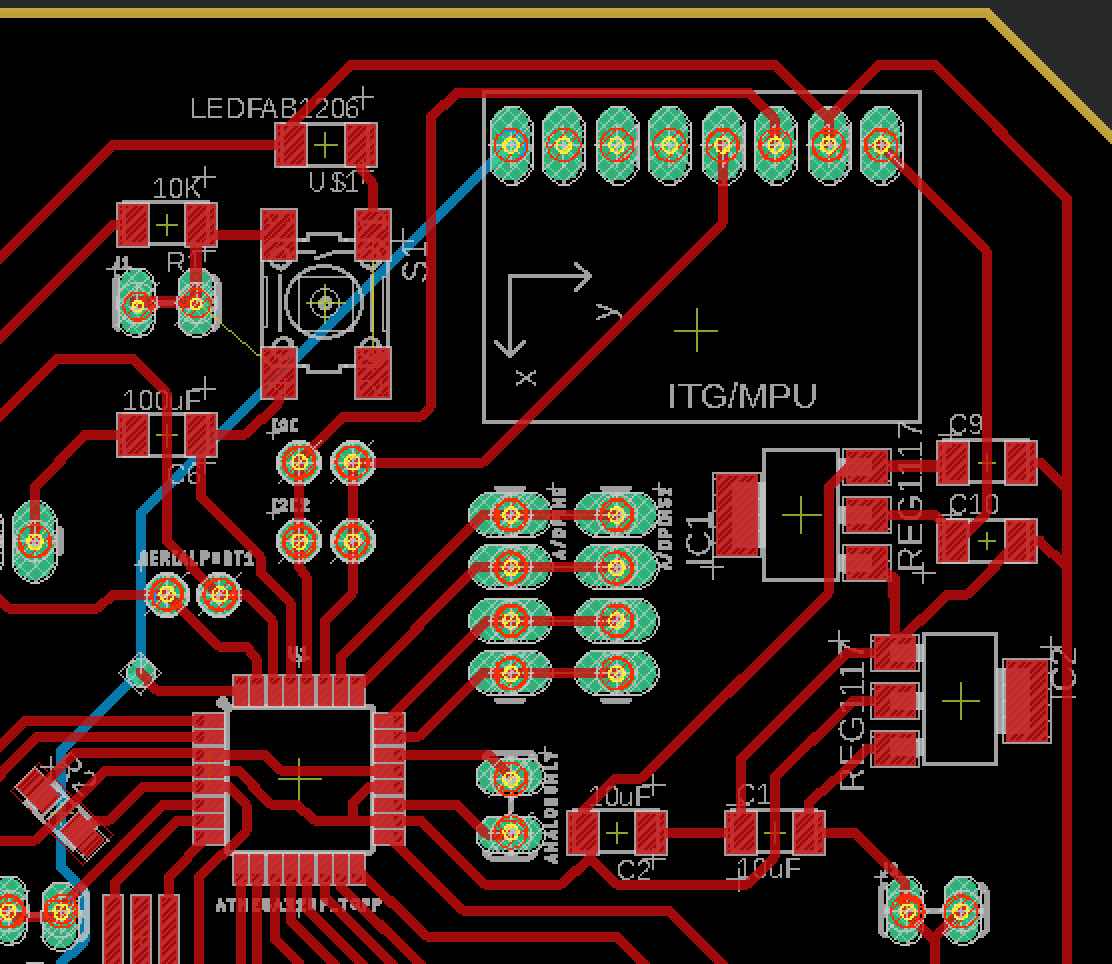
The accelorometer board uses I2C to communicate with my board, this means initially it requires a voltage source, ground and connection to the SDA and SCL pins on my board. I might require an interrupt pin to integrate a standby energy saving function which turns on the walker if any movement was sensed. So I integrated these connections and the size of the chip on my main board as seen below. The connections are shown individually to the right.
In the example code, I removed all parts not required and left only the pitch and roll which reperesent the lateral tilting of the chip. Once the board was connected, I uploaded the ammended code to the board and opened the serial monitor to survey the values. A video of this can be seen below.
Distance tracking
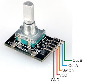
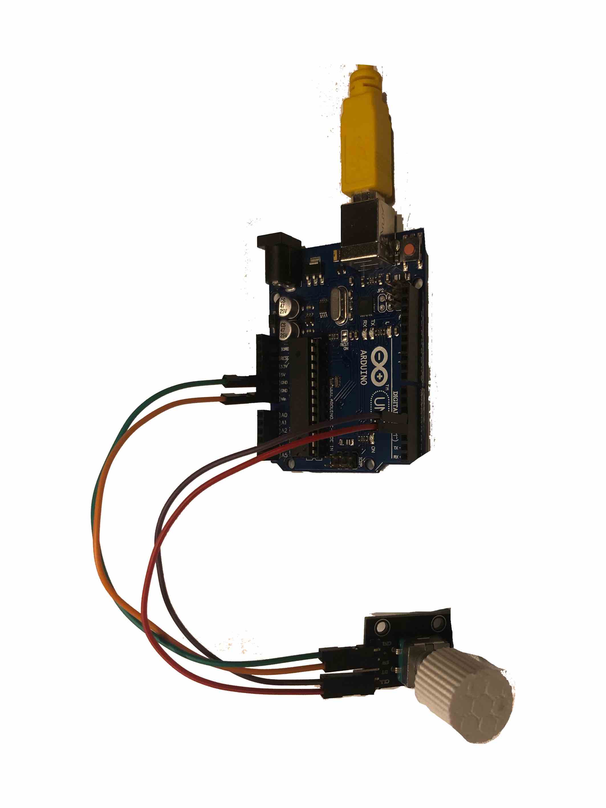
To measure the distance moved by the walker, I have decided to attach a rotary encoder to each of the front wheel axis. Initially for this week, I worked with one encoder, aiming to understand how it works and develop a basic framework for the code.
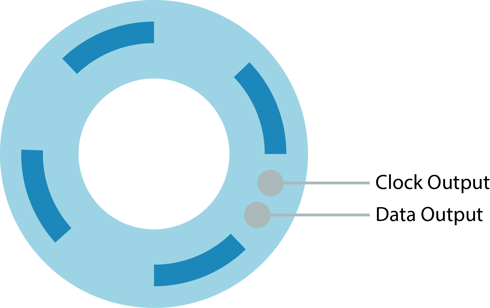
The encoder is constructed as seen in the diagram to the right. Two output sensing points are at equal distances from eachother. There are also VCC connected pads at equal distances placed on the rotary part. Once the pads contact the output points, a square wave output results 90 degrees out of phase between each output. Depending which output is sensed first, we can sense if the rotation is clockwise or anti-clockwise. d model of a half clenched hand.
I hooked up the roatary encoder to digital pins on the board as well as VCC and GND. Then I wrote the sketch below to read the values of the outputs and depending on the order to calculate it as a step. I also measured how many clicks the encoder turns, which resulted in 40. Meaning that each step is 18 degrees. Since the radius of the wheel is 55m, then the circumference is approx. 34.6 cm. So each step means the wheel moved 0.865 cm.
#define clk 3 //clock connected to pin 3
#define data 4 //data connected to pin 4
float counter = 0; //counter variable
int state; //state variable to sense movement
int laststate; //variable to compare with previous state
float distancemeters; //value in meters
void setup() {
// put your setup code here, to run once:
//setup input pin modes
pinMode(clk, INPUT);
pinMode(data, INPUT);
//begin serial at 9600 baud rate
Serial.begin(9600);
//measure initial state
laststate = digitalRead(clk);
}
void loop() {
// put your main code here, to run repeatedly:
//read current state then compare with previous state to see if ther is movement
state = digitalRead(clk);
if (state != laststate)
{
if(digitalRead(data) != state) //clockwise vs anticlockwise
{
counter=counter+0.865;
}
else
{
counter=counter-0.865;
}
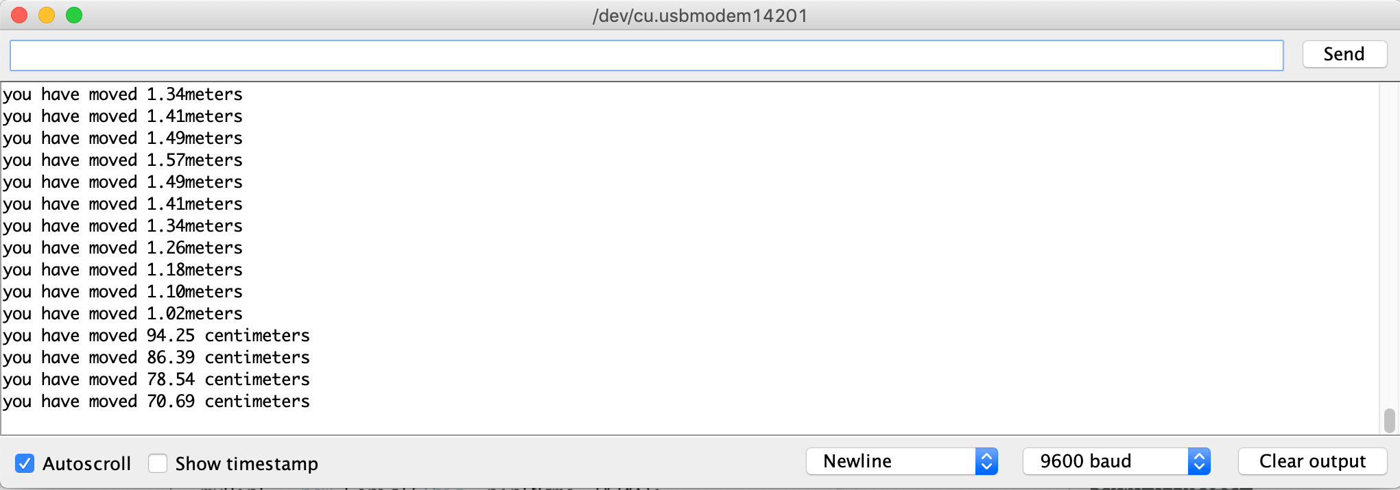
Serial.print("you have moved ");
if (counter > 100)
{
//if statements to convert to meters when over 100 cm
distancemeters=counter/100;
Serial.print(distancemeters);
Serial.println("meters");
}
else
{
Serial.print(counter);
Serial.println(" centimeters");
}
}
//save current state as previous state
laststate= state;
}
Heart rate and SpO2 sensing
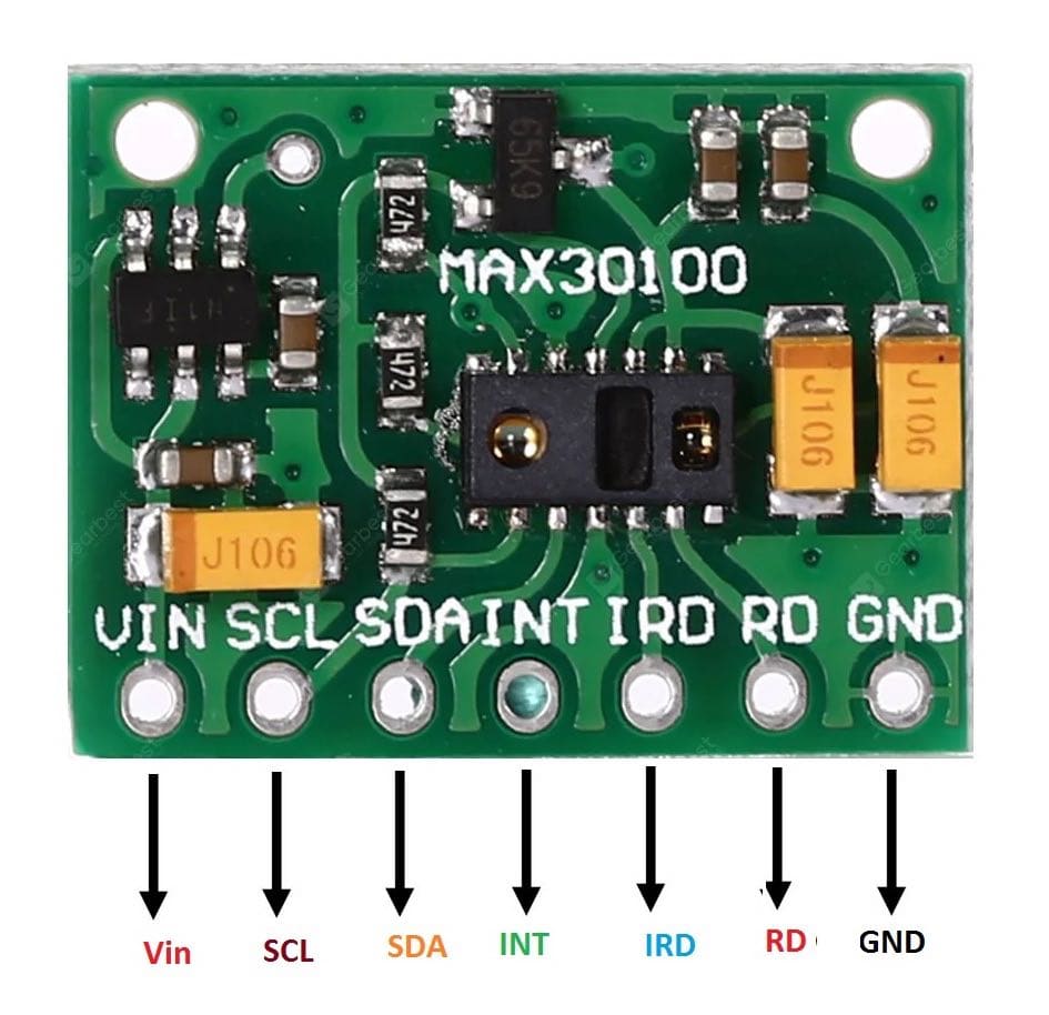
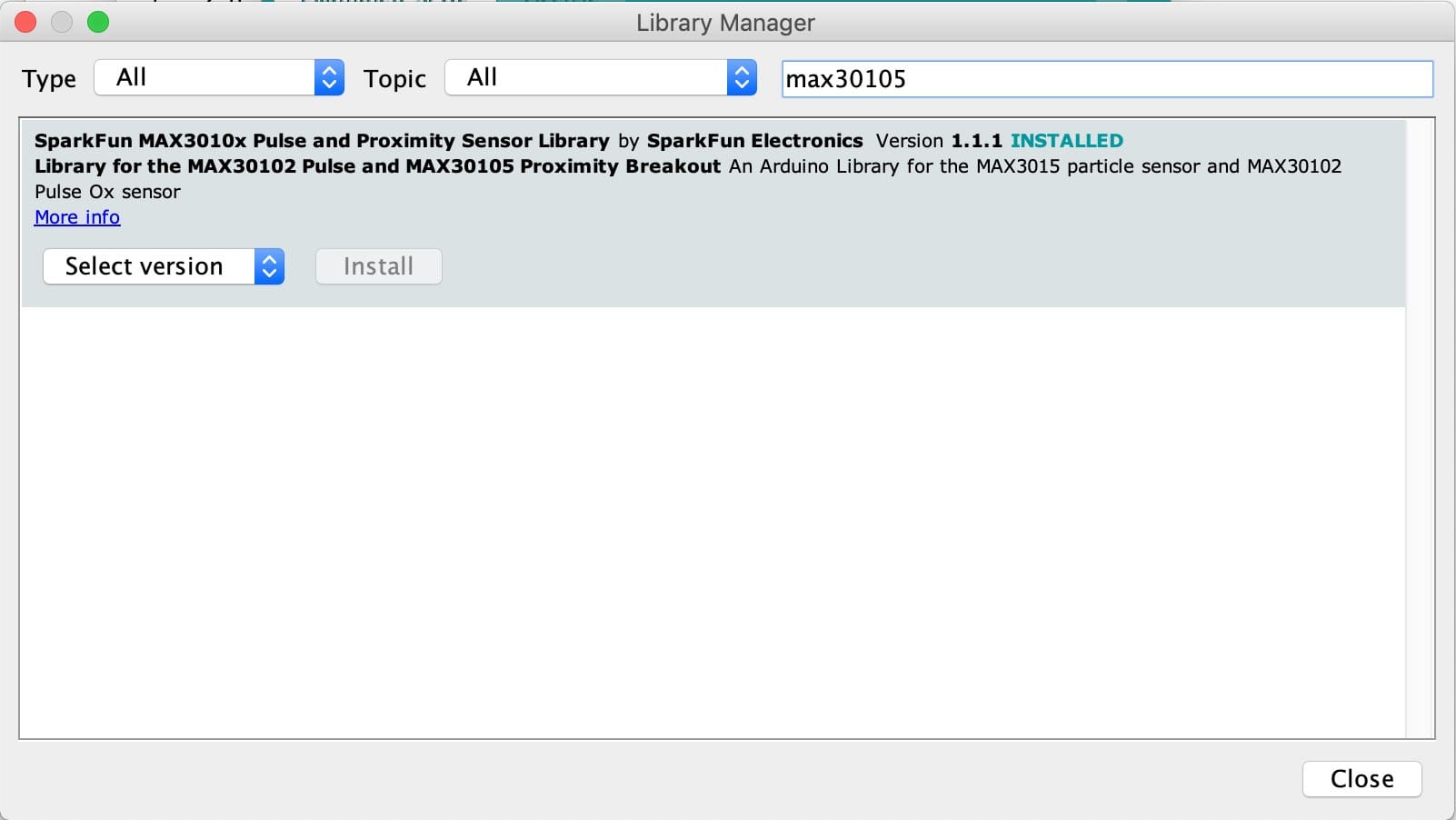
For the heart rate and oxygen levels, I'm using the SparkFun Max30105x sensor. It is a compact sensor for testing and prototyping and comes with details on how to connect/program it . The diagram to the right illustrates the pinouts. The heart rate sensor also comes with its own library which saves me time having to deduce my own signal processing code. The example code provided with the library, can be downloaded from the arduino library manager as shown below.
Similarly to the gyrometer, I changed the code to output the values I want to be able to further process them. two values indicate if HR and SpO2 levels are available while the other two values represent the actual data.
#include <Wire.h>
#include "MAX30105.h"
#include "spo2_algorithm.h"

MAX30105 particleSensor;

#define MAX_BRIGHTNESS 255

#if defined(__AVR_ATmega328P__) || defined(__AVR_ATmega168__)
//Arduino Uno doesn't have enough SRAM to store 100 samples of IR led data and red led data in 32-bit format
//To solve this problem, 16-bit MSB of the sampled data will be truncated. Samples become 16-bit data.
uint16_t irBuffer[100]; //infrared LED sensor data
uint16_t redBuffer[100];  //red LED sensor data
#else
uint32_t irBuffer[100]; //infrared LED sensor data
uint32_t redBuffer[100];  //red LED sensor data
#endif

int32_t bufferLength; //data length
int32_t spo2; //SPO2 value
int8_t validSPO2; //indicator to show if the SPO2 calculation is valid
int32_t heartRate; //heart rate value
int8_t validHeartRate; //indicator to show if the heart rate calculation is valid

byte pulseLED = 11; //Must be on PWM pin
byte readLED = 13; //Blinks with each data read

void setup()
{
  Serial.begin(115200); // initialize serial communication at 115200 bits per second:

  pinMode(pulseLED, OUTPUT);
  pinMode(readLED, OUTPUT);

  // Initialize sensor
  if (!particleSensor.begin(Wire, I2C_SPEED_FAST)) //Use default I2C port, 400kHz speed
  {
    Serial.println(F("MAX30105 was not found. Please check wiring/power."));
    while (1);
  }

  Serial.println(F("Attach sensor to finger with rubber band. Press any key to start conversion"));
  while (Serial.available() == 0) ; //wait until user presses a key
  Serial.read();

  byte ledBrightness = 60; //Options: 0=Off to 255=50mA
  byte sampleAverage = 4; //Options: 1, 2, 4, 8, 16, 32
  byte ledMode = 2; //Options: 1 = Red only, 2 = Red + IR, 3 = Red + IR + Green
  byte sampleRate = 100; //Options: 50, 100, 200, 400, 800, 1000, 1600, 3200
  int pulseWidth = 411; //Options: 69, 118, 215, 411
  int adcRange = 4096; //Options: 2048, 4096, 8192, 16384

  particleSensor.setup(ledBrightness, sampleAverage, ledMode, sampleRate, pulseWidth, adcRange); //Configure sensor with these settings
}

void loop()
{
  bufferLength = 100; //buffer length of 100 stores 4 seconds of samples running at 25sps

  //read the first 100 samples, and determine the signal range
  for (byte i = 0 ; i < bufferLength ; i++)
  {
    while (particleSensor.available() == false) //do we have new data?
      particleSensor.check(); //Check the sensor for new data

    redBuffer[i] = particleSensor.getRed();
    irBuffer[i] = particleSensor.getIR();
    particleSensor.nextSample(); //We're finished with this sample so move to next sample

    Serial.print(F("red="));
    Serial.print(redBuffer[i], DEC);
    Serial.print(F(", ir="));
    Serial.println(irBuffer[i], DEC);
  }

  //calculate heart rate and SpO2 after first 100 samples (first 4 seconds of samples)
  maxim_heart_rate_and_oxygen_saturation(irBuffer, bufferLength, redBuffer, & spo2, & validSPO2, & heartRate, & validHeartRate);

  //Continuously taking samples from MAX30102.  Heart rate and SpO2 are calculated every 1 second
  while (1)
  {
    //dumping the first 25 sets of samples in the memory and shift the last 75 sets of samples to the top
    for (byte i = 25; i < 100; i++)
    {
      redBuffer[i - 25] = redBuffer[i];
      irBuffer[i - 25] = irBuffer[i];
    }

    //take 25 sets of samples before calculating the heart rate.
    for (byte i = 75; i < 100; i++)
    {
      while (particleSensor.available() == false) //do we have new data?
        particleSensor.check(); //Check the sensor for new data

      digitalWrite(readLED, !digitalRead(readLED)); //Blink onboard LED with every data read

      redBuffer[i] = particleSensor.getRed();
      irBuffer[i] = particleSensor.getIR();
      particleSensor.nextSample(); //We're finished with this sample so move to next sample


      Serial.print(F(", HR="));
      Serial.print(heartRate, DEC);

      Serial.print(F(", HRvalid="));
      Serial.print(validHeartRate, DEC);

      Serial.print(F(", SPO2="));
      Serial.print(spo2, DEC);

      Serial.print(F(", SPO2Valid="));
      Serial.println(validSPO2, DEC);
    }

    //After gathering 25 new samples recalculate HR and SP02
    maxim_heart_rate_and_oxygen_saturation(irBuffer, bufferLength, redBuffer, spo2, & validSPO2, & heartRate, & validHeartRate);
  }
}
WiFi
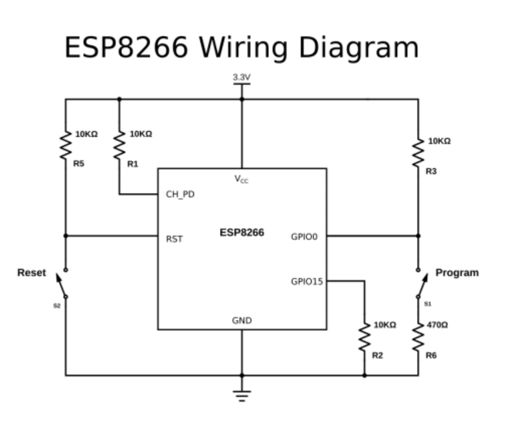
For this week's assignment I am using the ESP 8266-12e WiFi module. It contains the chip required for Wifi communication and an antenna. However, some components and connections are required to allow programming and usage of the chip. I initially referred to the , to learn more about these connections. I was kinda lost, it being the first time using such a module, so I found this , which provided me with all the information I needed to design my board.
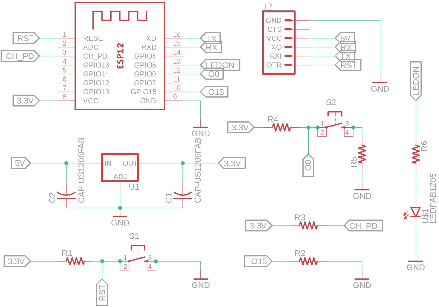
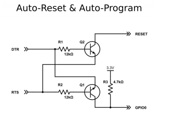
The schematic shown on the right is the one described in the tutorial. I broke down the circuit schematics to make it easier for me to connect the pins in my schematic. I also added a 3.3V voltage regulator.
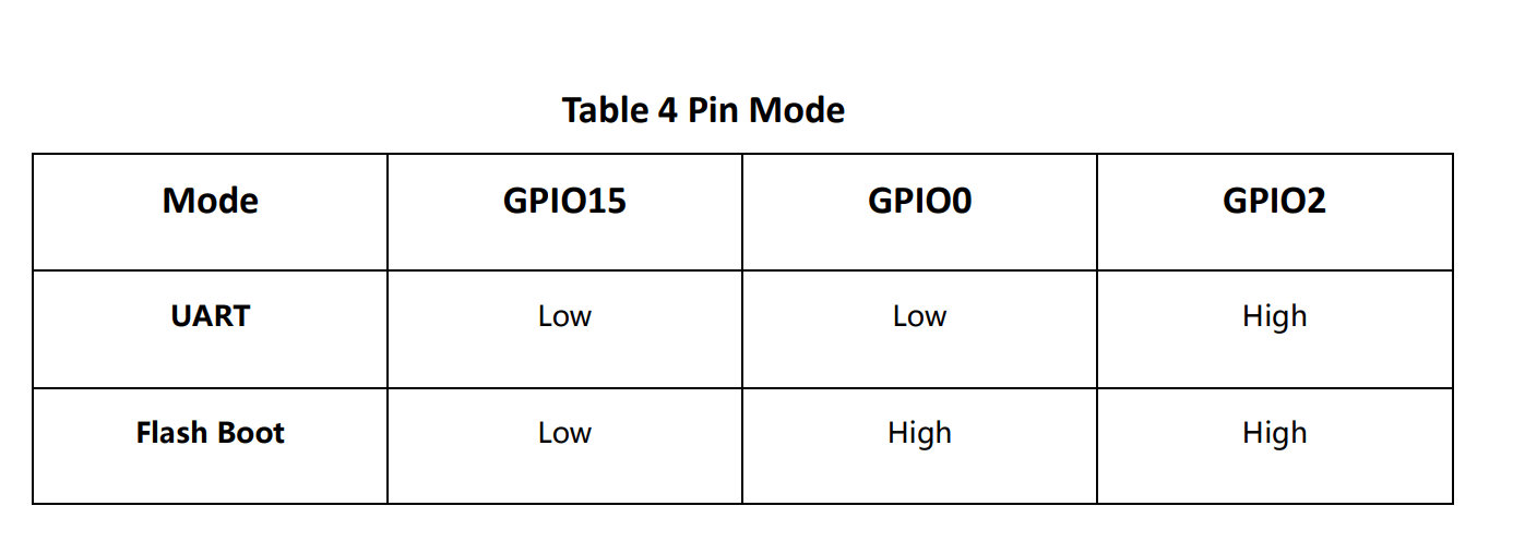
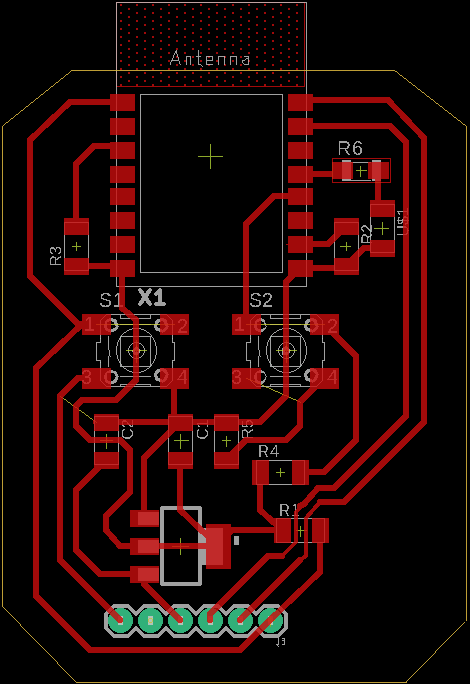
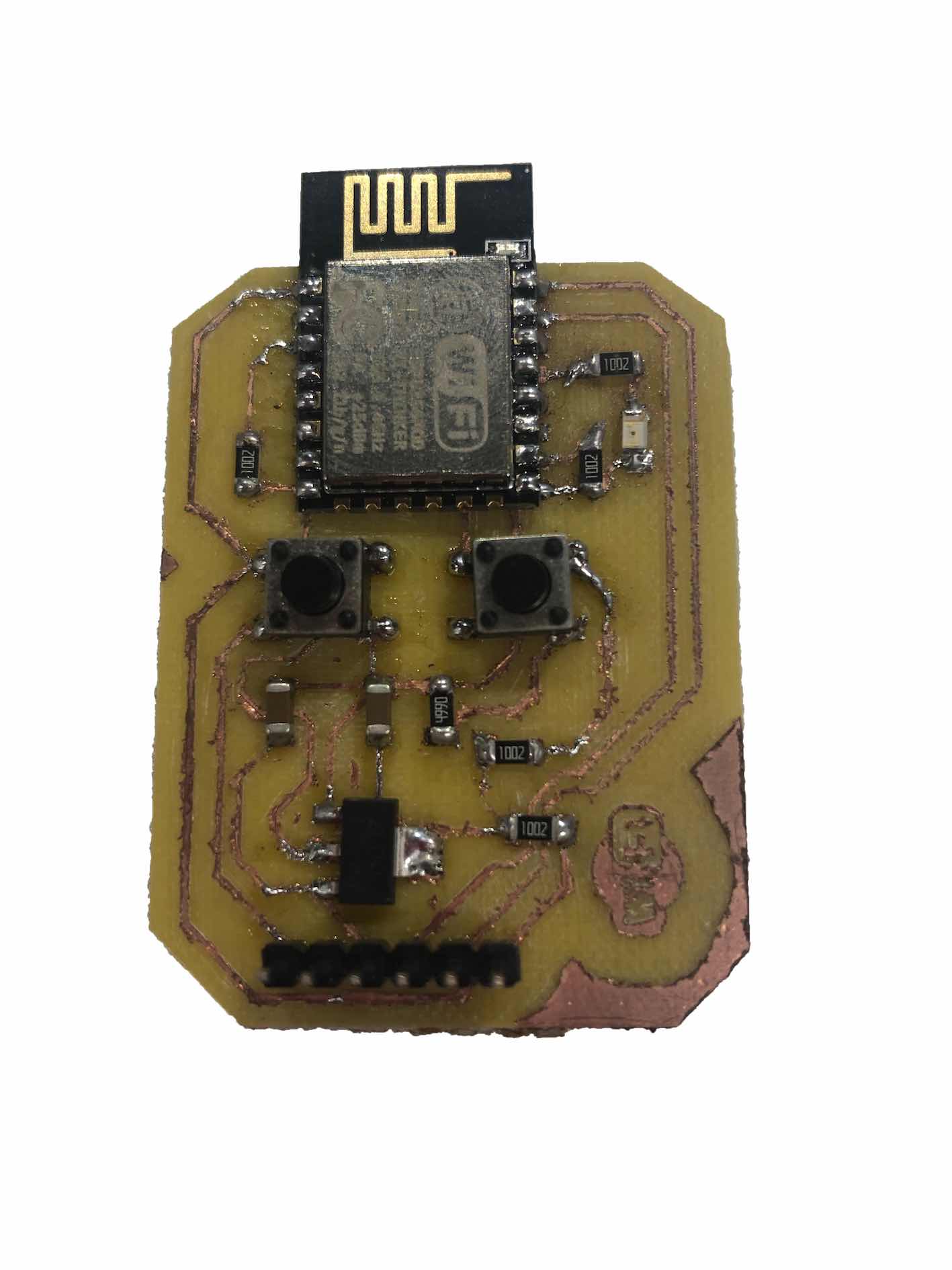
The final board contained two buttons for resetting and flashing the module, as well as an LED connected to an output pin in order to indicate when the chip is working. A connection to an FTDI connection was included to allow direct communication to the chip which is required for programming. All other connections were done according to the table on the right, from the datasheet.
The board design was designed to look like a face and include the WiFi logo. It was important to have the antenna sticking out for better connection and to prevent interference. The board design can be seen on the right alongside the milled product board looked like. It was a bit rough in terms of finish since the endmill had chipped halfway through, but I used it after checking all the connections were fine using a multimeter.
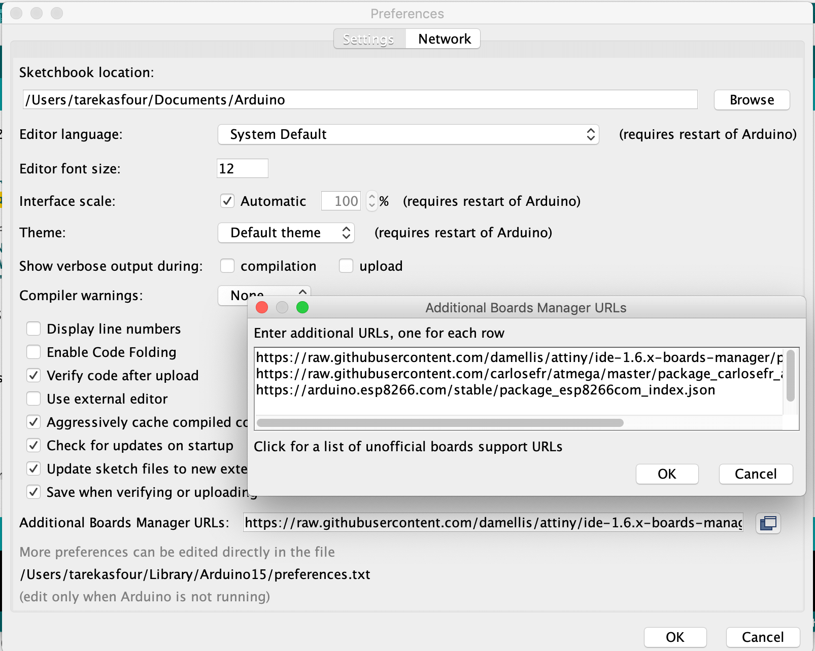
To program the board I downloaded the ESP8266 library by adding http://arduino.esp8266.com/stable/package_esp8266com_index.json to the additional board managers field in the arduino ide preferences.
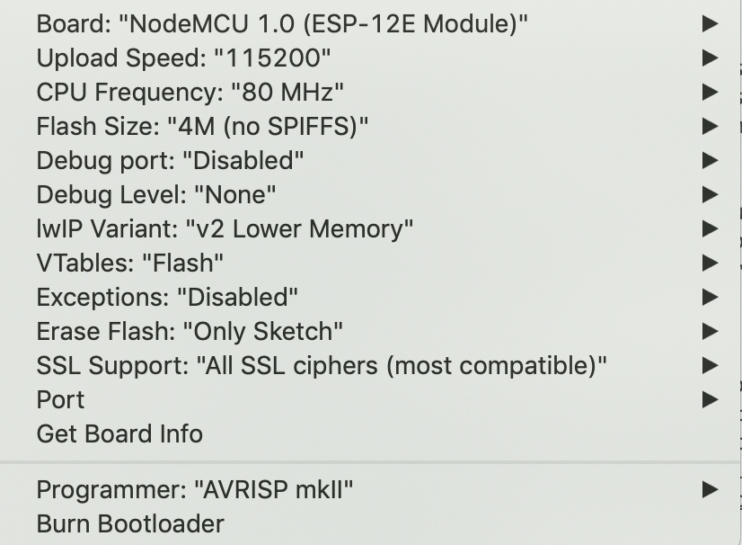
Once the library is downloaded, open board manager, search for esp8266 and make sure its installed. Then pick the Node 1.0 12E board with the following settings from the board menu in the toolbar.
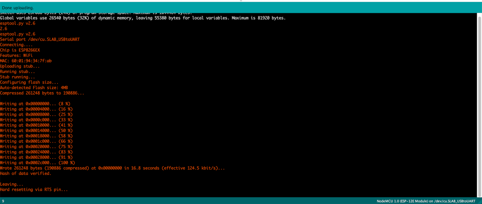
To check the board and burn the first sketch, I decided to upload an empty sketch. The analog button on the right connected to IO0 has to be pressed during programming. The other button is reserved for flashing the chip, but wont be required right now. There is an automatic reset circuit that I later discovered (shown on the right), but this works fine for the time being. The following was the output in the console terminal, indicating a successful upload.
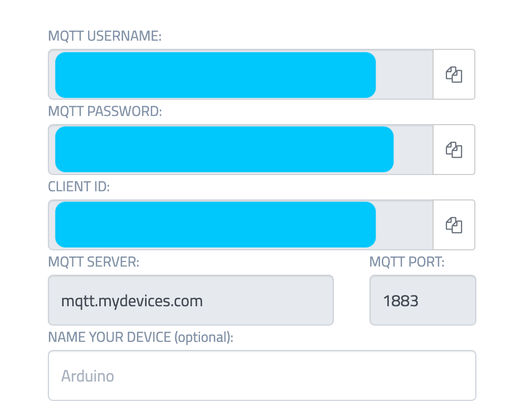
I then wanted to use the board by uploading a simple program that allows it to communicate using cayenne. I included the special key assigned to my WiFi board, as well as my cayenne username and password. this is required in order to gain access to the personal server.
#define CAYENNE_PRINT Serial
#include <CayenneMQTTESP8266.h>
// WiFi network info.
char ssid[] = "ssid";
char wifiPassword[] = "wifiPassword";
// Cayenne authentication info. This should be obtained from the Cayenne Dashboard.
char username[] = "MQTT_USERNAME";
char password[] = "MQTT_PASSWORD";
char clientID[] = "CLIENT_ID";
unsigned long lastMillis = 0;
void setup() {
Serial.begin(9600);
Cayenne.begin(username, password, clientID, ssid, wifiPassword);
}
void loop() {
Cayenne.loop();
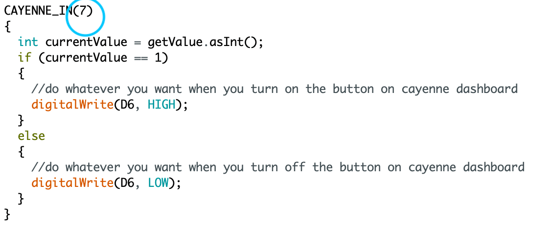
//Cayenne input function from channel 7 on dashboard
CAYENNE_IN(7)
{
int currentValue = getValue.asInt();
if (currentValue == 1)
{
//turn light on when you turn on the button on cayenne dashboard
digitalWrite(D6, HIGH);
}
else
{
//turn light off you turn off the button on cayenne dashboard
digitalWrite(D6, LOW);
}
}
}
Cayenne is an MQTT service, that communicates with your IOT device over Wifi. I will go into more details during interface and week, so for this week I set up a simple program to blink an LED once a button is pressed on the Cayenne dashboard. The first video is the trial on a breadboard, and the second is for an on-board led that I installed on my custom WiFi board.
Interface
A used MQTT communication over WiFi using a service called cayenne. The server provides a customizable dashboard as well as a dedicated server which allows you to create a custom interface to view and relay data.
First of all, one is required to sign up and set up an account. Each account has a username, a password. Then your IOT device can be specified and added, each device has its own key. Keep these credentials as they will be required when setting the code up.
The next step is downloading the ESP cayenne on the Arduino IDE. This is not really required but it will save you a lot of time and frustration. The library comes with a ready example for the esp8266 that I am using. The example contains the sending and receiving functions. I based my own code on this, specifying certain input channels that receive sensor data, with others that digitally control a light and a buzzer.
// This example shows how to connect to Cayenne using an ESP8266 and send/receive sample data.
// Make sure you install the ESP8266 Board Package via the Arduino IDE Board Manager and select the correct ESP8266 board before compiling.

//#define CAYENNE_DEBUG
#define CAYENNE_PRINT Serial
#include <CayenneMQTTESP8266.h>

// WiFi network info.
char ssid[] = "ssid";
char wifiPassword[] = "wifiPassword";

// Cayenne authentication info. This should be obtained from the Cayenne Dashboard.
char username[] = "MQTT_USERNAME";
char password[] = "MQTT_PASSWORD";
char clientID[] = "CLIENT_ID";

unsigned long lastMillis = 0;

void setup() {
	Serial.begin(9600);
	Cayenne.begin(username, password, clientID, ssid, wifiPassword);
}

void loop() {
	Cayenne.loop();
}

// Default function for sending sensor data at intervals to Cayenne.
// You can also use functions for specific channels, e.g CAYENNE_OUT(1) for sending channel 1 data.
CAYENNE_OUT_DEFAULT()
{
	// Write data to Cayenne here. This example just sends the current uptime in milliseconds on virtual channel 0.
	Cayenne.virtualWrite(0, millis());
	// Some examples of other functions you can use to send data.
	//Cayenne.celsiusWrite(1, 22.0);
	//Cayenne.luxWrite(2, 700);
	//Cayenne.virtualWrite(3, 50, TYPE_PROXIMITY, UNIT_CENTIMETER);
}

// Default function for processing actuator commands from the Cayenne Dashboard.
// You can also use functions for specific channels, e.g CAYENNE_IN(1) for channel 1 commands.
CAYENNE_IN_DEFAULT()
{
	CAYENNE_LOG("Channel %u, value %s", request.channel, getValue.asString());
	//Process message here. If there is an error set an error message using getValue.setError(), e.g getValue.setError("Error message");
}
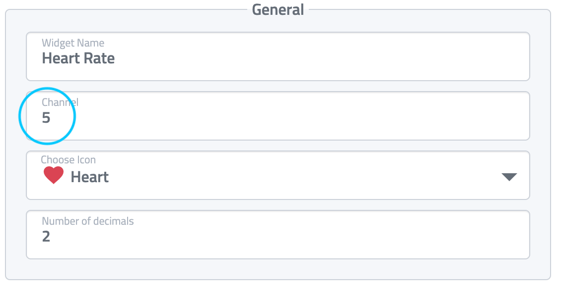
Each I/O corresponds to a channel on cayenne. This channel can be linked to different dashboard widgets to visualize the data or represent a button.
I/O channel code
Widget channel settings
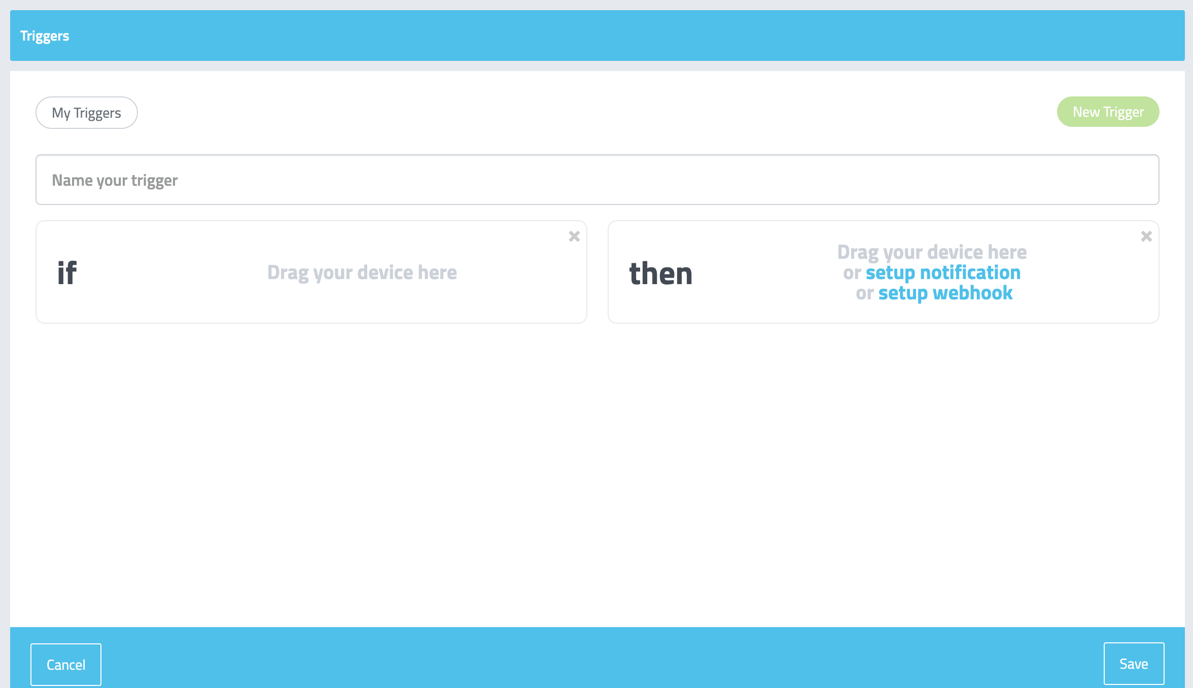
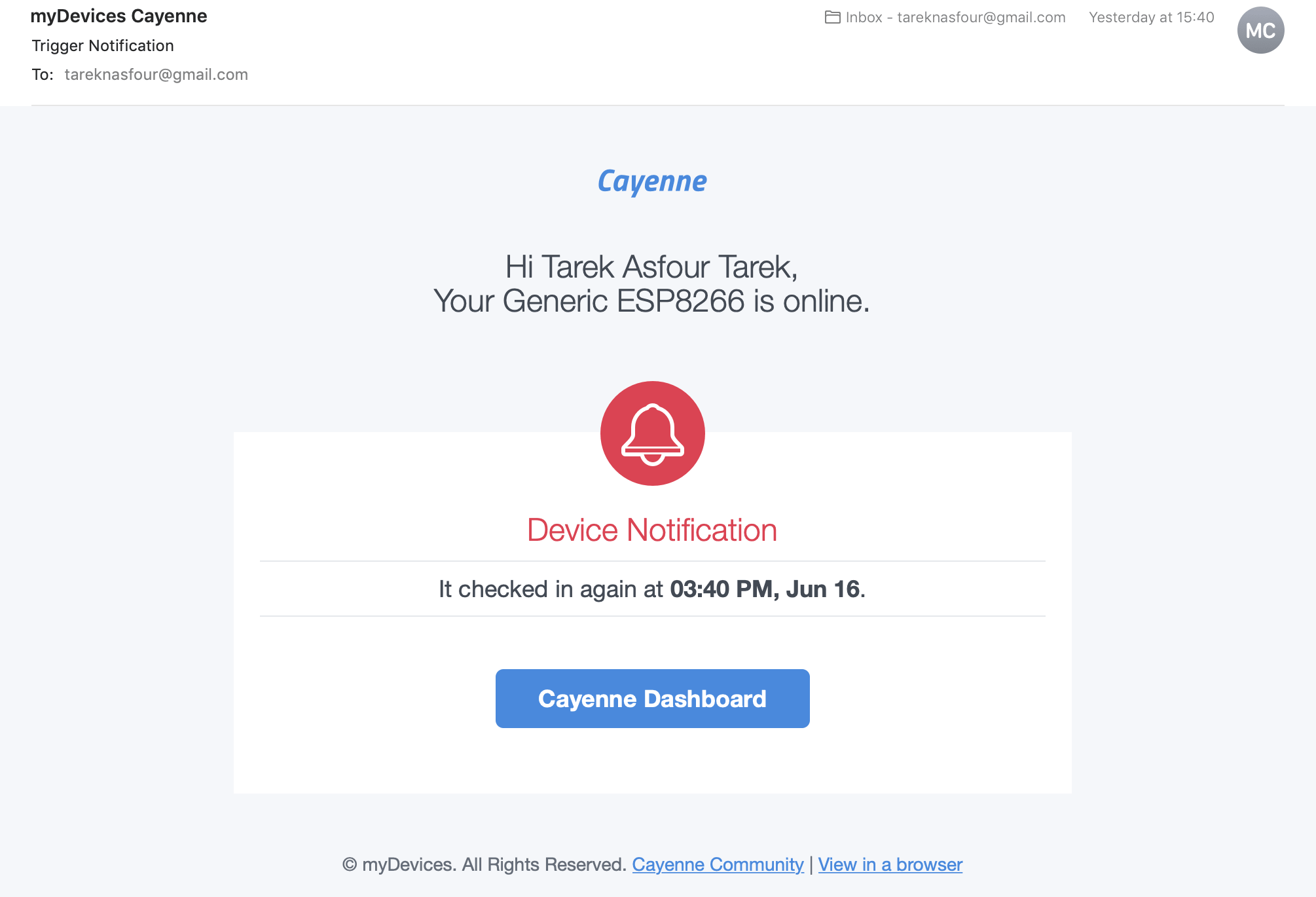
Cayenne also allows the setup of a trigger. This means when a certain value/limit is triggered, a certain action is performed. I used a simple trigger, where as soon as the board is powered in , an email is sent to my email.
Trigger setup
Email notification
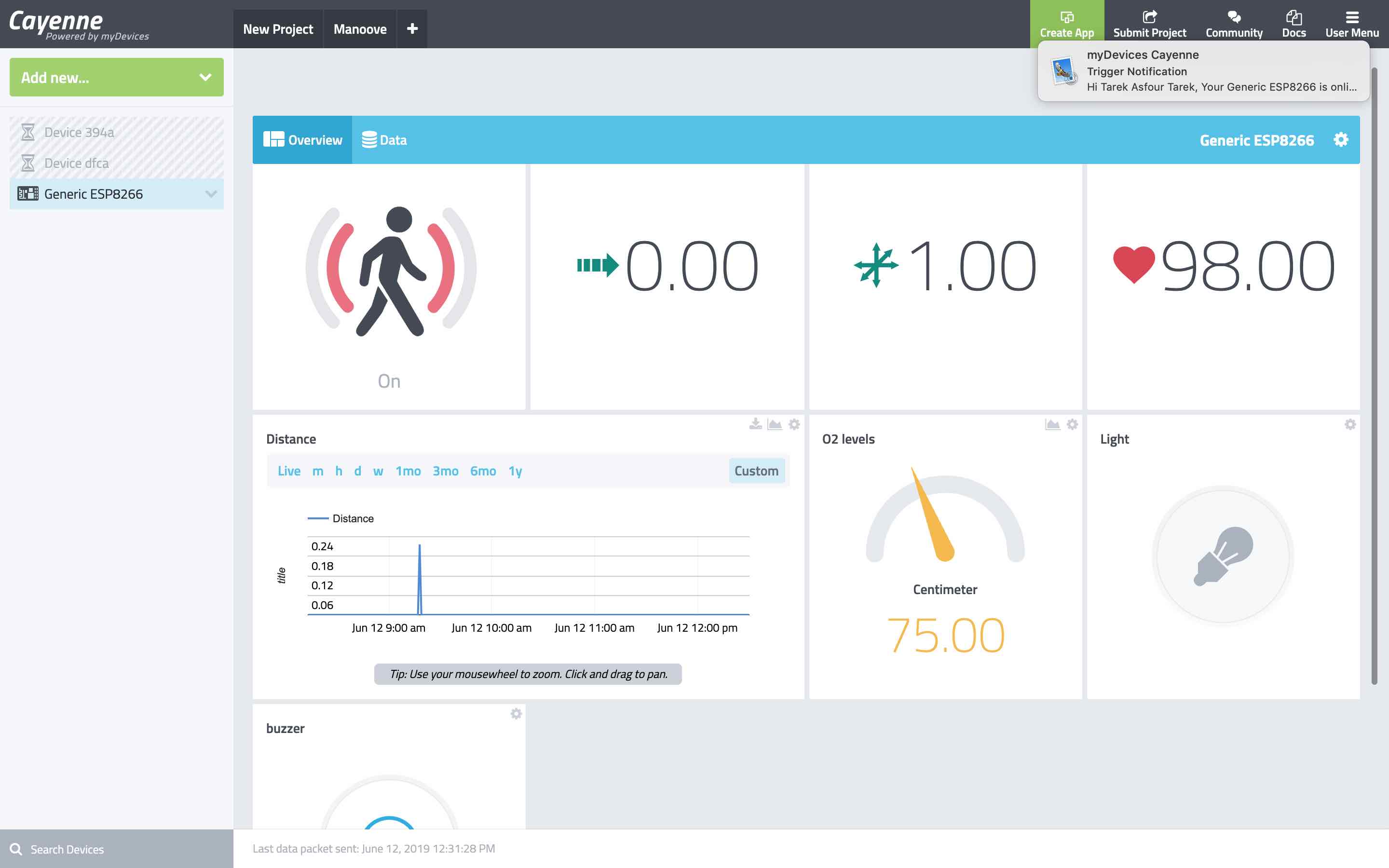
After setting up all inputs and outputs coming from my processing boards, I organized a dashboard to view all the data for my final project. Each widget had a different look to display the data in the most suitable manner.
-min.png)


-min.jpg)