17. Machine design
This week I worked on tasks refered to Machine design in order to ‘work and communicate effectively in a team and independently; design, plan and build a system; analyse and solve technical problems; recognise opportunities for improvements in the design’.
This was the assignment:
-
Group assignment:
- Plan and make a machine.
- Document the group project
(Follow this link to see the group assignment)
-
Individual assignment:
- Document your individual contribution.
SUMMARY
Have you?
- 1. Explained your individual contribution to this project on your own website > DONE
On the group page, has your group
-
1. Shown how your team planned and executed the project > DONE
-
2. Described problems and how the team solved them > DONE
-
3. Listed future development opportunities for this project > DONE
-
4. Included your design files > DONE
-
5. Upload 1 minute video (1920x1080 HTML5 MP4) to your_lab_site/machine.mp4 + slide (1920x1080 PNG) into http://fabacademy.org/2019/labs.html (demo live during video) > DONE
ASSIGNMENT | Machine plan and making
Project management
First thing was to review the tasks to be afforded in a new meeting after the class:
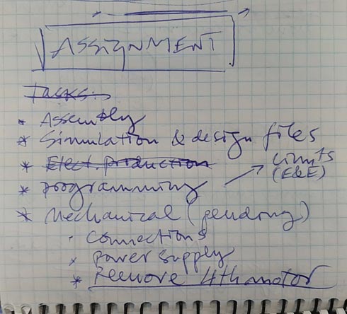
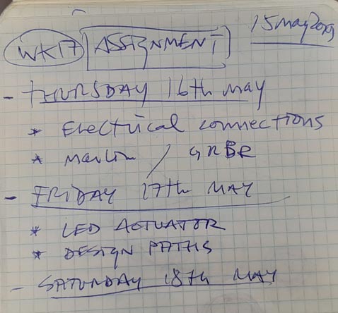
Here, the documentation tasks are remaining
Assembly
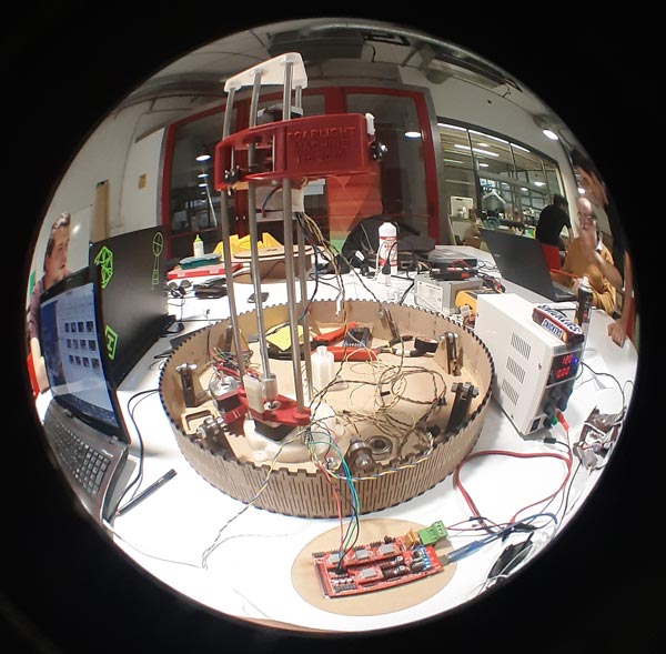
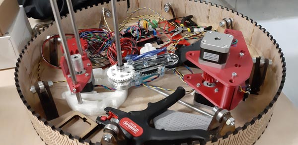
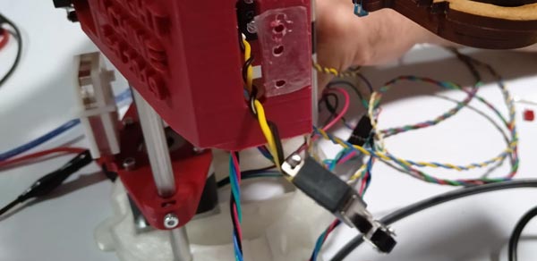
Electrical components must be integred to the system, like power supply, wires and controller board (Arduino + Ramps).
For that, some parts should be replaced/modified:
-
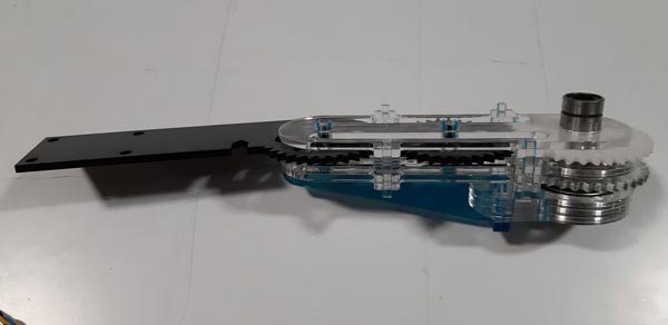
Arm:
-
The first arm gear had a bit little small hole to rotate around the axis than the desired/needed, so that piece was replaced for another one that allowed the movement to be easier.
-
The last piece (LED actuator holder) must contact one of the 2 end stop switches, so the end stop had to be relocated.
-
The Z stepper down end stop was compromised by the one of the arm motors that would hit the bottom 3D printed tower piece before the end stop would be activated, so, a new piece needed to be designed and lasercut produced to fix this.
-
-
Base:
-
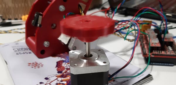
The motor should be well fixed to the base, so a piece was designed, produced and added specifically for that.
-
The Arduino board was placed into the base into a simple MDF 3mm glued piece that allowed the easy put/remove action.
-
The central piece was re-designed and PLA 3D printed because of the big thickness of the whole wires that must be connected from the motors, LED actuator and end stop switches to both the power supply and the Arduino controller. For that, the MDF 5mm rotatory base in where the tower is placed, had to be also cut with a bigger whole in which the central piece is placed with a new bigger bearing.
<!–
–>
-
-
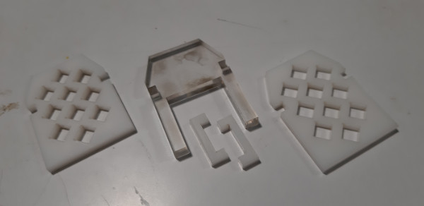
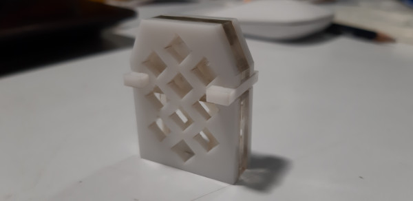
Tower:
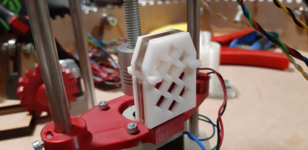
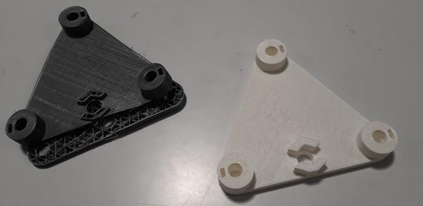
- The tower cap was a little bit broken because of the 3D printing resolution. In order to reinforce the axes fixing, this piece was 3D re-printed with higher in-fill settings to replace the first one.
- The big piece that holds the 2 motors was a little bit bended by screw forces separating its 2 parts on the extreme. To solve that, a little acrylic 3mm fit system was designed, lasercut and added making it look nice than before.
- All linear bearings were lubricated to help the whole big piece to slide better along the axes.


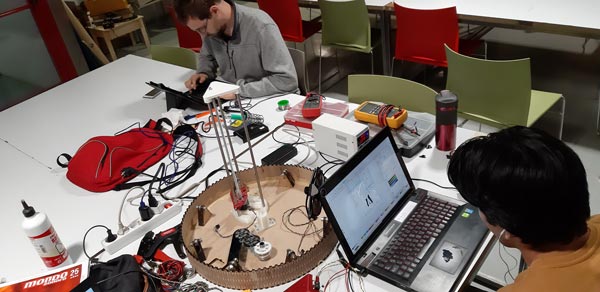
Programming
Once the whole machine’s parts were reviewed and updated, we tried to move the steppers, enable the end stops and to control the LED.
- Arduino + Ramps + Marlin
This system controls the 4 stepper motors and the end stops with a master code. Also, it gives power supply to the LED board.

- Marlin
Main Marlin instructions:
- G-CODE
Main G-CODE instructions:
* M114 > returns steppers positions
*
We began the programming process by uploading to the Arduino board the Marlin (VERSION)(LINK) firmware, reviewing line by line the whole setup.
Then, we tried a testing file… and found with different problems:
-
Z stepper.
It was stoping suddendly many times when changing the spin direction.
At first, we thought that the matter was related with the stepper axis itself, as if the motor would be forced at the moment to install the 3D printed piece by pressure.
We discarded this possibility removing the 3D printed piece (gear).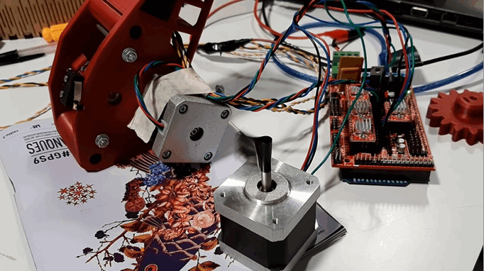
We red something about that kind of problems related with the minimium power supply needed.
Solution:
So, we tried to fix the problem by adjusting the power supply with the Ramps shield drivers potentiometers (manually) to 0.4 (A).
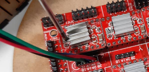
And it worked! No similar problems after that.
-
X and Y stepper motors.
We could use them separately when using Pronterface (LINK), a software that connects directly with the drivers and controls the machine by many ways. The problem appeared when trying to use the test file, because it had some code to link both motors that we couldn’t find. The fact was that when we activated the Z motor, it worked well, but when we activated the X one, the Y moved too, and viceversa.
Also, in general, we felt some rare behaviours with this code, and we couldn’t understand it perfectly.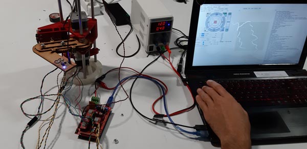
(VIDEOS)(IMAGE)
Solution:
We downloaded another code (NAME-LINK) and followed the new source instructions and explanations, and problems disappeared inmediately. Here, we celebrated the power of a good documentation, and decided that the first light drawing that we make will be sended to the tutorial author as a gift. (Also, it would be interesting to send a comment to the previous code author to help to the community to avoid our frustating situations)Another problem we had was very frustating because no solution appeared to be possible. The fact was that the X and Y stepper motors, the 2 which control the 2 rotations of the arm, were not working well. The movement wasn’t be fluid and smooth; it was very hard and appeared to be stucked.
We thought that maybe the MDF 3mm by acrylic 3mm change of the whole parts of the arm could be the reason, so we built and re-built the arm with different parts and materials many times, as the previous versions were working. Finally, the only explanation for that behaviour could be the very hard friction between the arm and the traction gears (X and Y steppers), so we decided to change the design to open a little space between gears, but then we realized that the motor fix holes were not circles, but rounded rectangles, so the motors, at any rebuilding time, were fixed too near to the arm, and that was generating a big pressure to the rotation of the arm to be made.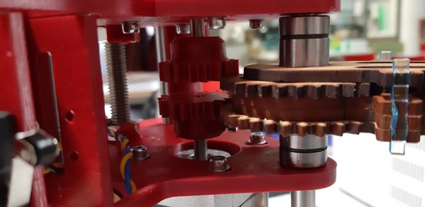
Just by un-screwing and moving the motors almost 1 mm and fixing them again, the arm recovered its smooth and easy movement.
(SMOOTH ARM MOVEMENT VIDEO)
Calibration
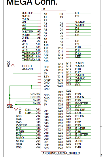
We found and used the connections map on Ramps according to the different components to be controlled (LINK).
The, we began to understand the code and to programm the steppers and the end stops.
We made the calibrations as follows:
-
Z displacement. Moving the motor x steps, measuring the distance between both positions and doing the calculations, we obtained the Z_FEED_RATE value. It must be 166.7 to displace 1 vertical mm by step. This is directly related to the rod thread step (0.86); this value must be introduced at the Marlin configuration file. By this way, we stablished a language to communicate with the motor to work with easy numbers.
-
X-Y movements. At first, we had 2 motors to control the arm rotations. X (the bottom one) controlled the arm whole rotation from the center axis. Y (the top one) controlled the half arm rotation. As this was doing the programming process more complex, we decided to control X and Y with just one motor (the X one, for example). The same stepper gear would rotate both half and whole arm gears at the same time. By this way, the arm movement with one motor would be just extend and flex bringing the LED, placed at the end of the arm, up and down from the rotation center on a straight line.
-
Base
-
End stops
When
(VIDEOS)
- RGB output PCB
This board has a code that controls the RGB LED behaviour.
Simulation & Design files
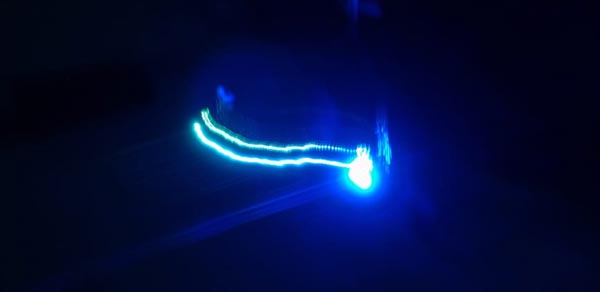
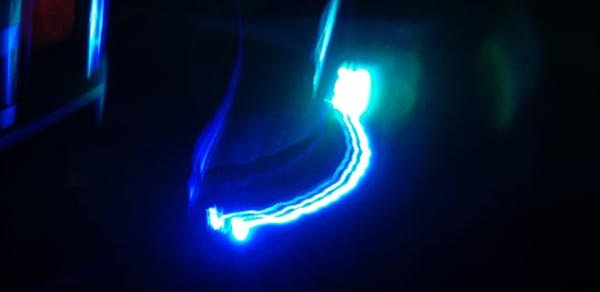
This is the G-CODE of a drawing generated writing the code line by line:
CODE
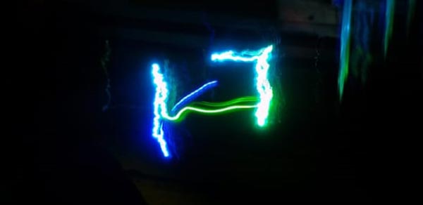
This is the result: the letter H.
Future development opportunities
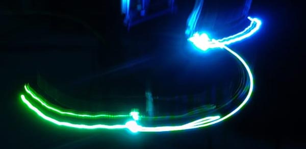
The machine could be improved by working on the LED actuator, adding it a LED strip and/or neopixel LED strip in order to obtain another light effects.
Problems
- Z HOME
When ‘homing’ with the Z stepper, all works fine until the end stop in activated. The motor seems to make its routine of stopping (touches end stop, goes in reverse a little bit, and continues a little bit again) so slowly. We tried to change this at the Marlin configuration file:
WHAT VALUE??
Tests


Results
H letter
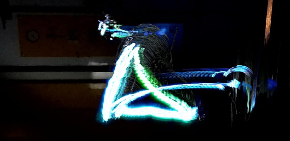
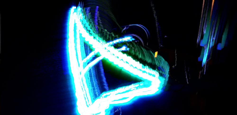
Triangle
Presentation video
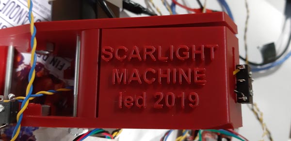
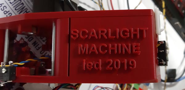
Here is the final video to present the ScarLight machine as a group assignment and as the result of almost 1 month working on ScarLight:
My contributions to the ScarLight project
As mentioned at the Mechanical design (week15) assignment, I worked in many different areas/stages of the project.
This time, I worked in a similar way, doing these jobs and being present on these tasks:
-
Project management
I have:
- managed the sharing platform and files through Google Drive
- took part on the job definitions, assignments and tasks supervision.
Some notes:
- In some way, the group worked better this time because of the previous experiences.
- The Google Drive system is still resulting confusing and non-productive. I think that this has to be with the fact that most of the people is not familiarized with the repository structure, which makes me think that persists a communication problem that maybe does not allow the group, in general, to be much more effective.
- At the end, the repository was used by needing, but -although it’s good to use things when they are on demand-, in this case, I think that that means that the group structure is not solid and has risks of forgetting something important, frustate the peope or even loosing the job.
-
Assembly
I have:
- adjusted the arm parts to make it lighter
- calibrated the arm stepper motors to solve the tracking issue with the arm gears
- lubricated parts and bearings
- built and rebuilt the whole machine many times…
-
Design
During the assembly process, many parts of the machine had to be modified to adjust little details, or just think a design new ones.
I worked on:- the arm, making it in acrylic and re-doing some parts
- the end stop issue, designing a new entire acrylic piece to be added to the base of the tower
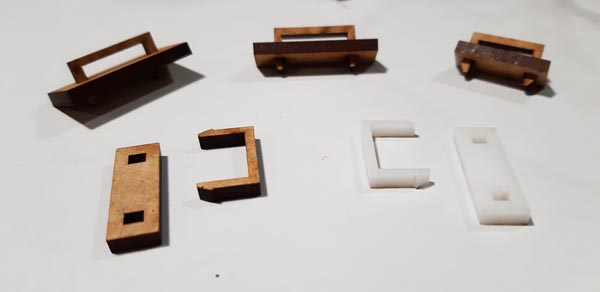
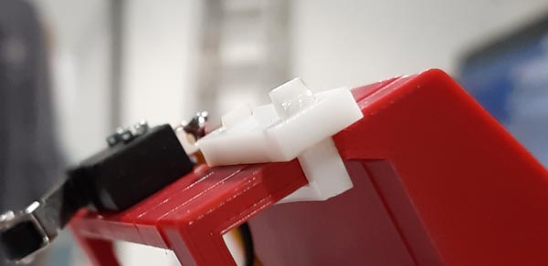
- the case join to mantain the parts connected and solid with a new acrylic tiny join system
- the base stepper support to mantain it hard fixed
- a kind of Arduino case to hold it in a kind of ‘pNp’ piece into the base.
-
Production/Fabrication
I produced with laser cutting machine:
- the new arm
- the stepper motor support
- the Arduino ‘case’
- the end stop piece
- the tower case join
I produced with 3D printer:
- the tower case (re-printed at higher resolution)
I worked with workshop tools on:
- the base (glue and press)
-
Programming
-
Documentation