10. Molding and casting
This week I worked on 3 task(s) on Molding and casting in order to familiarize with 3D milling and materials and procedures to mold and cast. These were the assignments:
-
Group assignment:
Review the safety data sheets for each of your molding and casting materials
Make and compare test casts with each of them
(Follow this link to see the group assignment) -
Individual assignment:
Design a 3D mould around the stock and tooling that you’ll be using, mill it (rough cut + (at least) three-axis finish cut), and use it to cast parts.
SUMMARY
-
Have you?
1. Explained how you designed your 3D mould and created your rough and finish toolpaths for machining > DONE
2. Shown how you made your mould and cast the parts > DONE
3. Described problems and how you fixed them > DONE
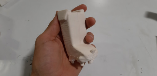
4. Included your design files and ‘hero shot’ photos of the mould and the final object > DONE
5. Reviewed the safety data sheets for each of your molding and casting materials, then made and compared test casts with each of them > DONE
ASSIGNMENT
Individual - Design a 3D mould, mill it and use it to cast parts
How it works (Principles)
- Molding/Casting is made to obtain new copies of any object or shape.
- Molding/Casting is based on the creation of a hollow space combining molds of the complementary sides of the final object
- Molds can be used once or more times to reproduce the object, depending on what kind of mold is drawn/produced
- Molding/Casting usualy follows these ordered material stages:
Rigid > Flexible > Rigid
> Note:
> Rigid to avoid deforming the final object during the curing process
> Flexible to allow a succesful and easy final object extraction - Molds/Contra-molds are made by additive (3D printing, casting, others…), substractive (milling) processes, or by a mix of both
- Molds/Contra-molds must be possitive/negative/mirrored, according to the number of molding/casting stages used and on the expected result
- Molds/Contra-molds must correctly cover all sides (views) of the design to make a complete reproduction
> Note: Sometimes, this implies to prepare more than the 2 usual molds - Molds/Contra-molds covering the whole final object must have holes for the casting process to pour the material into the mold and also to let go out the air into it
- Molds/Contra-molds design must consider the casting process in order to decide the position that the final object material needs to be poured into the mold
- Casting must avoid the presence of bubbles into the poured material
- Casting involves a few hours curing process
Molding/Casting steps (in order)
-
3D reference: heightmap | 3d object
Depending on what kind of object to obtain, a different 3D model or heightmap is drawn in the computer.
The drawing must be considered as the mold that will receive fluid material into it to do the subsequent casting.Molding/Casting could be made with 2 complementary molds or it may would be necessary to make many molds to be combined, so it’s probably that the number of molding sides define the number of drawings to do (depending on the shape itself, because of its possible simetries and so…).
About the drawing:
-
Views VS Sides
The final object can be casted using the different volume 3D views. Depending on the complexity, a min/max number of views will define the number of sides to be used to generate complementary molds.
This is based on the maximum visible geometry from a point of an ortogonal view, and this is applied to the 3 axes milling process in which the mill can only access to the material in the normal direction of the bed (Z), so the plane (bed) at which the normal (mill) belongs, is the milling (top) view. It means that it is impossible to see/access to neither the back side or angled (invisible) parts of the object from there. For example, the Moon: just 2 different views that complement between them. In a way, a sphere needs only 1 side mold because of the simmetry of the spherical body: the view is the same, wherever it’s projected: a semi-sphere from both sides. On the other hand, in the specific case of the Moon, molds will must be different because of the uniques geography and bump of the surface). -
3D model VS Greyscale map
A greyscale map could be used to indicate the milling routes in x, y and z axes, considering white and black as the opposite height extremes. White is the highest point and black is the lowest one. The greyscale represents the intermediate height points. This is also known as alpha channel. The greyscale views can be obtained from a 3D drawing software once the 3D model is already drawn, each one representing the molding sides (views) of the object. In any case, both the alpha (.png) channels and the 3D model (.stl) could be interpretated by machining software in order to prepare the routing paths. -
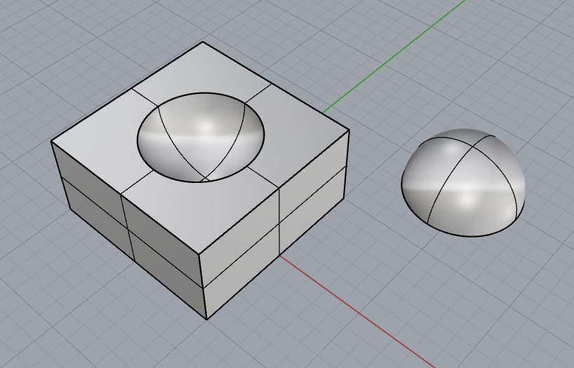
Positive VS Negative
This refers to the relief of each side of the mold or counter-mold.
If the casting is made in 2 stages, the drawing of the resulting mold must be the ‘negative’ shape of the desired object, such as a bas-relief, in order to directly obtain the object from the first, unique and rigid mold.
This process has the restriction that the mold is probably lost during the final object extraction, and also the final object can be compromised.
If the casting is made in 3 stages, the first mold must be a contra-mold (positive, as the final object itself). It will generate a flexible negative mold that, at the end, will generate the final object.
This flexible mold allows the final object to be extracted easily and also to make new many copies of it.
A positive 3D drawing means the final object volume as is, on relief; like a plane with the side view of the object over it like in the additive boolean operation.
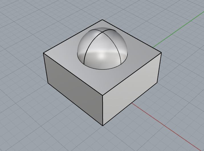
A negative 3D drawing means the opposite: the low relief of the object on a plain, like the substrative boolean operation.
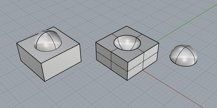
These concepts must be taken into account when preparing the drawings for the molds because of possible simmetry issues, specifically when deciding if the molding/casting is going to be done in 2 or steps, and when deciding if the desired result is going to be positive or negative. These are the main rules:
- positive result in 2 steps > mold drawing must be negative and mirrored
- positive result in 3 steps > mold drawing must be positive and put into a bigger volume uncap ‘box’.
> Important note:
> Also, a contra-box could be negative included into the box for the last casting step
>
-
negative result in 2 steps > mold drawing must be positive, mirrored and put into an uncap ‘box’ of the same (or higher) volume
-
negative result in 3 steps > mold drawing must be negative, mirrored and put into an uncap ‘box’ of the same (or higher) volume. Also a contra-box could be included on the drawing for the last casting step
Important note:
Also, a contra-box could be negative included into the box for the last casting step
The negative process is the inverse of the ossitive, so just start from the 2nd step of the process and make the changes needed to contain the material poured on the mold.
- positive result in 2 steps > mold drawing must be negative and mirrored
-
2 sides VS Decomposition
There are other more complex figures that need more than the 2 opposite projections/molds to generate the final object. It usually depends on the parts of the object responding to the 3 dimension planes that are solved in a better way if are made with complentary molds. -
Connectors VS Nesting
When molds have to enjoy between them to receive the final material pour, joints must be implemented to the molds to avoid parts to move accidentally making the result invalid because the parts slide or because of partial separations/unperfect fitting. These compatible positive and negative connectors should be also drawn on each mold as part of the design and they can have any shape.
As this method works, molds perimeters also can nest one into the other, ensuring that no final material poured into the mold could go out.
-
-
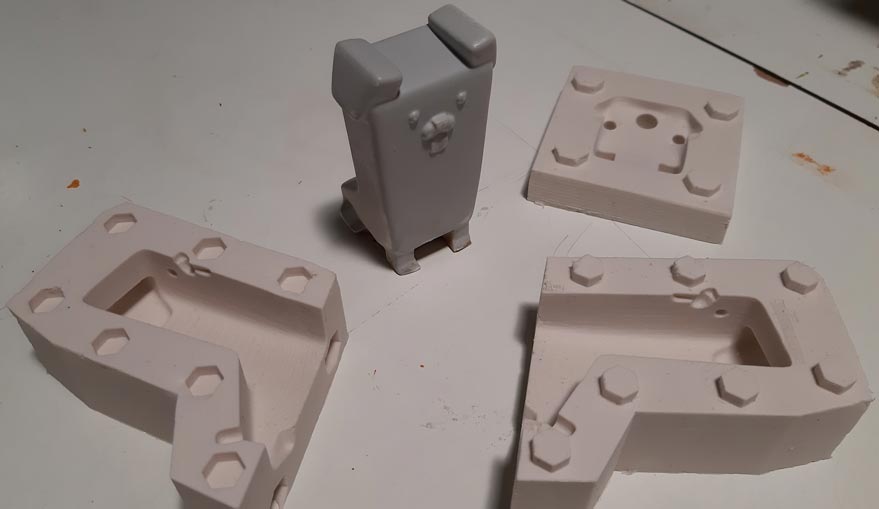
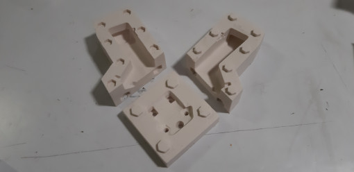
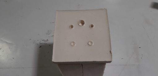
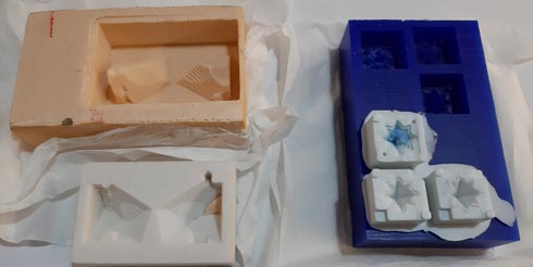
Mold production (RIGID): mill | print | cut
The 1st step mold can be produced by additive/substactive ways, for example 3D printing the mold, or milling a stock. Anyway, the process is made in 3D, and the resultant mold has to be precise.
In the case of milling the piece, the process involves, as less, a rough job able to remove the most material as possible to bring the 3D drawing into a physical mold. Also, it is usual to made a refining job with thiner pieces, which rise the final resolution. This 2 jobs can cost the same milling time, each other on its specific role.
Once the milling processed are finished, the mold should be completely ready for the casting step. -
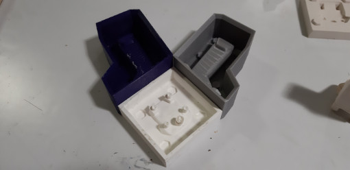
Contra-mold production (FLEXIBLE): cast | cure
The 2nd step mold is made by pouring the fluid material into the 1st step mold previously produced by 3D drawing and milling a stock.
This material, for example silicon, is mixed with other product to have a chemical reaction in order to start a curing process that will change the fluid material into a solid state.
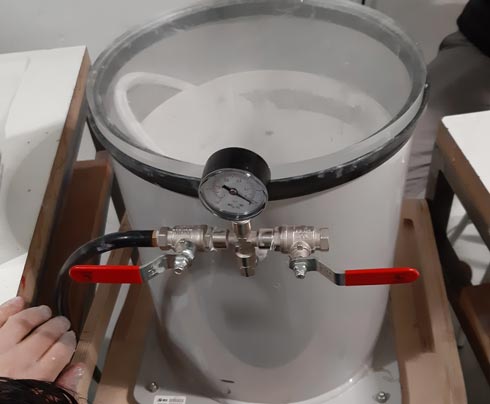
This process has to be made in a few minutes from the mixing step because of the speedy curating reaction. Also, the material has to rest into the mold without bubbles into it. Bubbles could be a problem for the appearence and for strength of the final object. Some methods are used to avoid/extract the bubbles, like settleling the material by numerous hits on the bottom of the mold or with the help of a vacuum machine to push them to the top part.
This whole process must return a flexible and precise mold able to reproduce many pieces of the same design, without forcing the final object to break during the extraction step. - Reproduction (RIGID): cast | cure
After that, the final material is casted into the produced mold, and the final object is obtained after the curing process. This last step takes many hours, depending on the material.
Example
Hole and chimmeney explanation
Molds made by 3D printing
Silicon contramolds and final object
Here are shown the whole steps
Here is shown another technique. The original shape to be cloned is put on a surface where to give it a ‘silicon shower’. Once the shape is covered and the silicon dry, both are put between 2 wet plaster pieces to obtain a rigid mold of the shape with the external silicon layer. Once the rigid mold is dry, it is separated to remove the original shape from the silicon, and it is closed again with the silicon in between. The final material is poured into the silicon (into the plaster) to obtain the final piece. (Depending on the original shape, this couldn’t be done without using the elastic silicon material)
Materials description
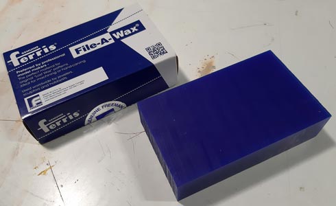
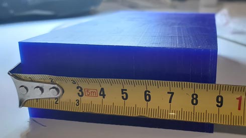
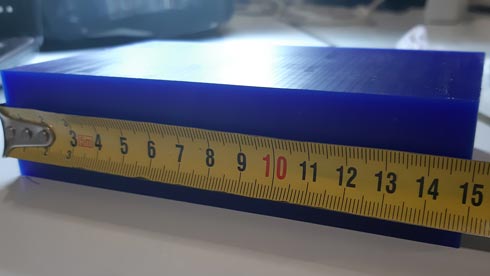
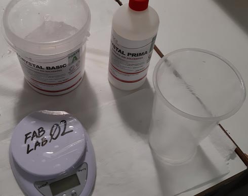
For this assignment I used:
machinable wax to produce the mold
tin silicon, acrilic polimer and crayons for casting.
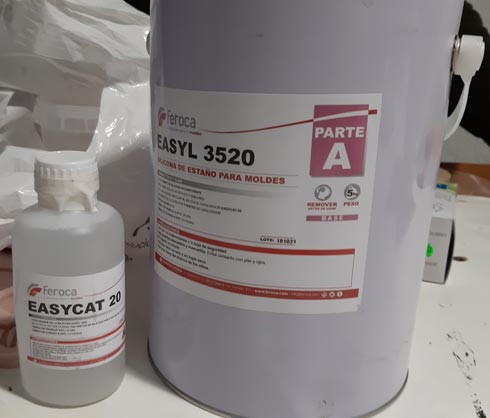
- Datasheets
Silicon EASYL 3520 + EASYCAT 20
Product > EASY L 3520
Proportion (mix) > 100:5 (5% catalizer)
Curing time > 4-5 hours
Resistence to breaking > 400%
Mix viscosity > 13000 cps
Working time > 20 min
Shore A hardness > 20
Traction resistance > 33 Kgf/cm
Color > White“Its main characteristics include its demolding capacity, its excellent fluidity and its high elasticity, for easy removal of complex reproductions”
There are no special risk specifications
EASYL 3520 + EASYCAT 20 datasheet
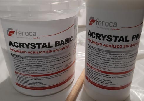
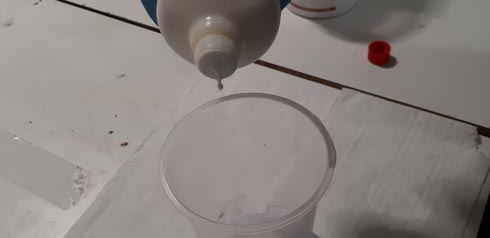
Resin ACRYSTAL BASIC + ACRYSTAL PRIMA
Product > ACRYSTAL BASIC + ACRYSTAL PRIMA
Proportion (mix) > 1:2,5 (liquid:powder in weight)
Curing time > 90% of the hardness is reached after 6 hours at 20 ° C. The complete hardening is obtained at 72 hours.
Working time > 8/10 min without retardant | Up to 90 min with retardant (between 17 and 20ºC)
Color > White“Non-toxic, odorless, easy to use, water-based cleaning of work tools, minimal exotherm. It can be reinforced with fiberglass, it does not attack the silicone molds.
Acrystal can be mixed with any water-soluble product. In case of liquid pigments, they will be applied to the liquid component while powder pigments will be added to the Basic Crystal powder component.
Silicone is the ideal mold for Acrystal, the absence of solvents and exothermic reaction the mold can extend its life up to 50 times compared to reproductions made with polyester resins.”There are no special risk specifications:
“Hazard identification: None“
“Hazardous substances contained: deleted”but there some conventional cares on:
- First aid
- Fire-fighting measures
- Measures in case of accidental release
- Exposure controls / personal protection
- others…
ACRYSTAL BASIC + ACRYSTAL PRIMA datasheets
Tools
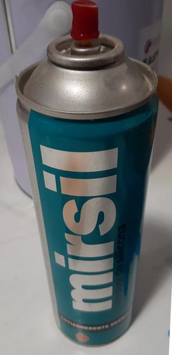
First, non-stick release agent (used on foam)
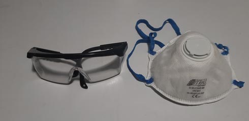
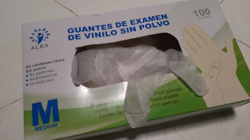
Second, protection for clothes, eyes, mouth, and hands
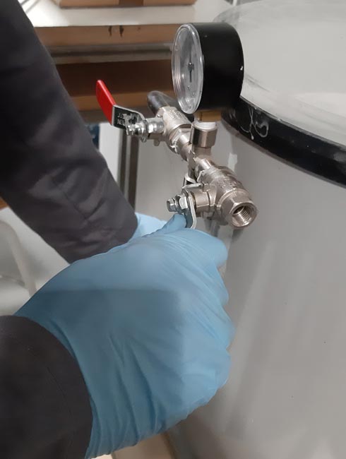
Vacuum machine
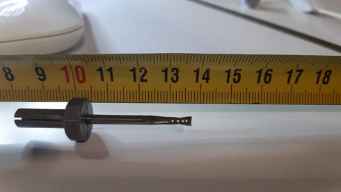
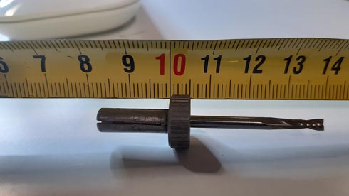
Mill kit
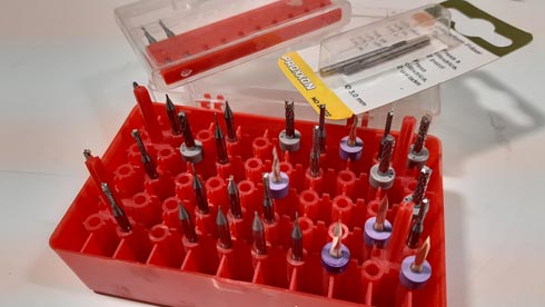
3.175 mm mill used on rough jobs
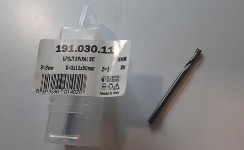
3.175 mm / 1.58 mm / 0.79 mm mills used on rough/finishing jobs
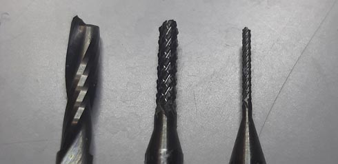
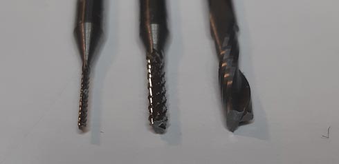
Some mill measures including collet, info needed for RhinoCAM
Precision scale
Design description
For this assignment I used a different version of the design I made in the 6th week (3D printing/scanning) (check it to see my past procedure).
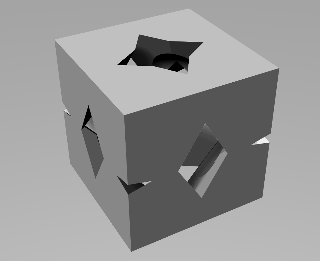
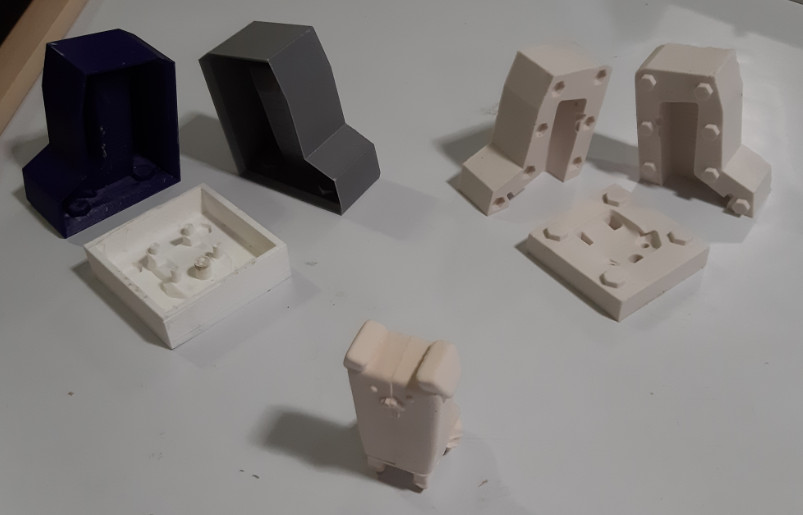
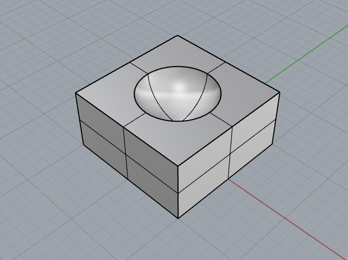
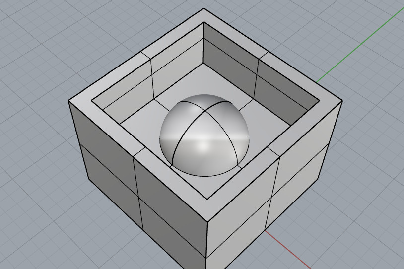
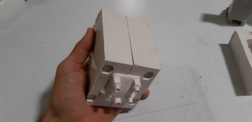
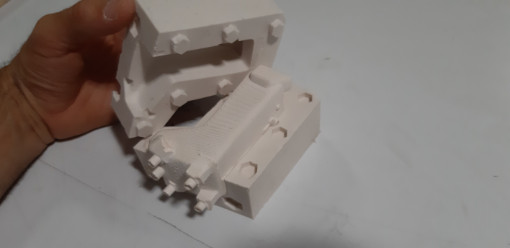
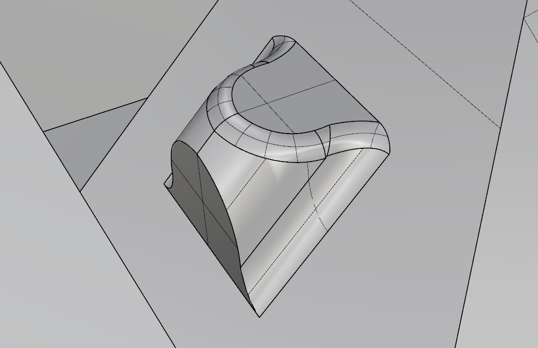
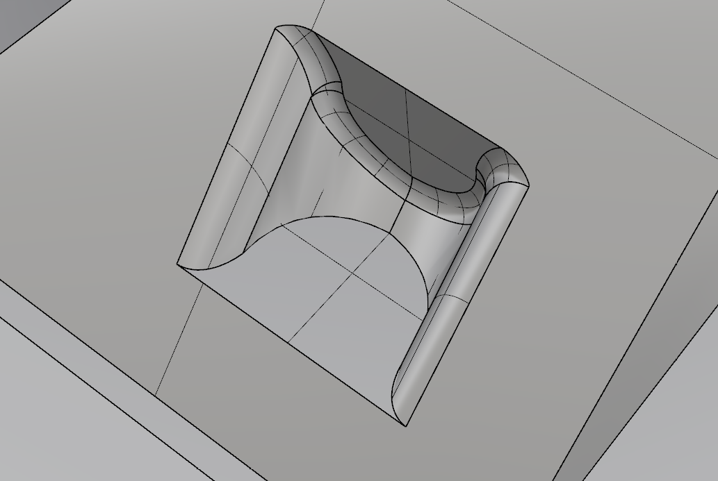
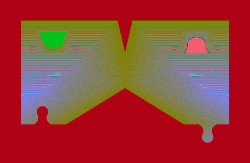
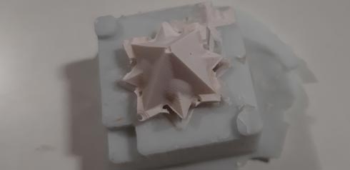
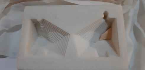
On this time, again, I thought in using modular assembly by designing a unique piece that could make 2 kind of figures just by duplicating and rotating it 90/180 degrees. My design is an 8-part hollow cube.
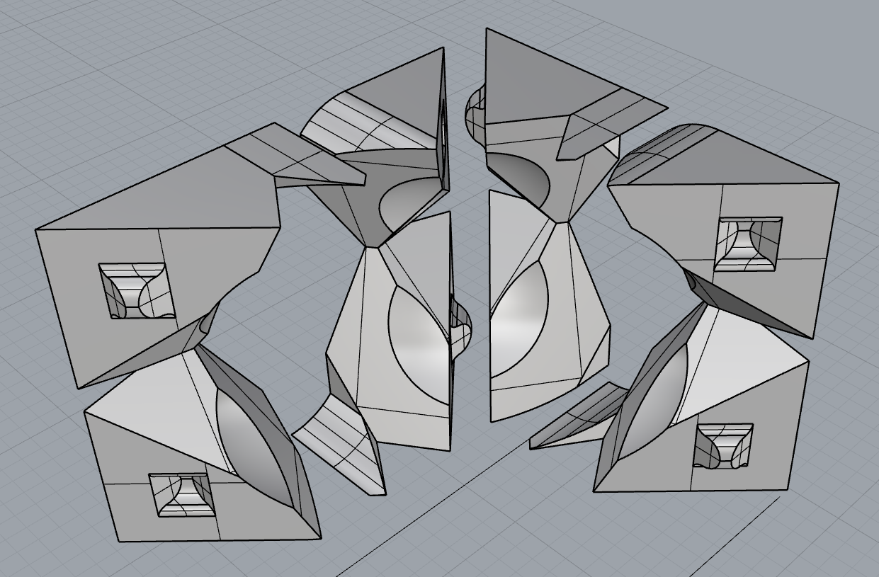
By this way, I could obtain results from a unique flexible mold, casting it 8 times and then assembling results; this returns the hollow cube. Also, from 8 flexible molds, a volume corresponding to the hollow of the cube could be casted.
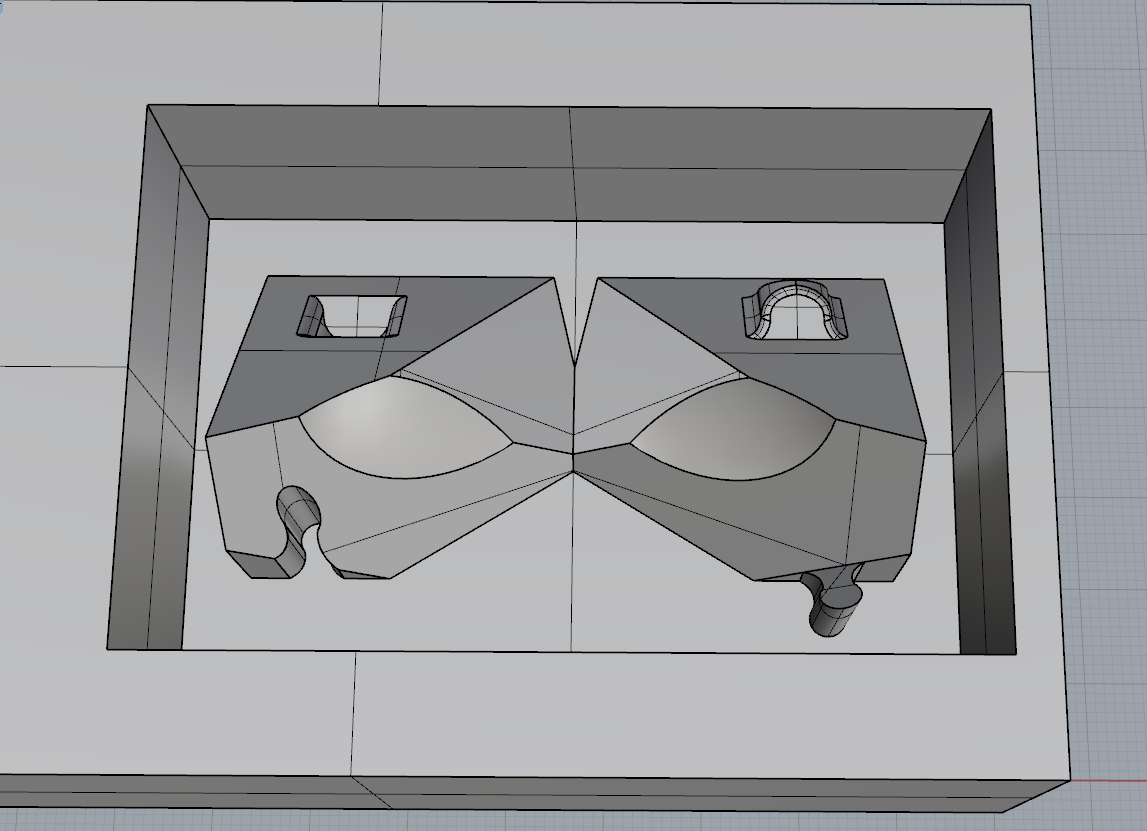
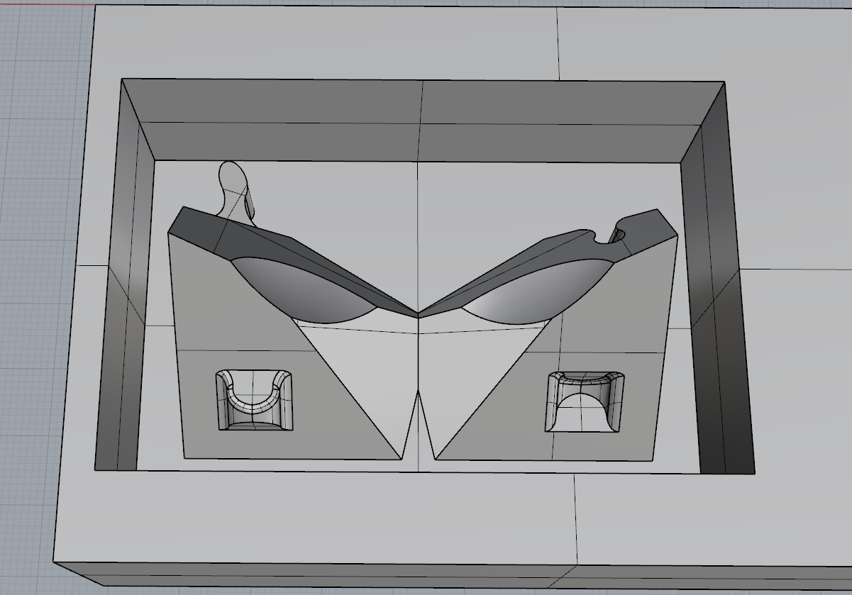
I worked on this unique and capable design a lot, mainly on the joints needed.
Also, I made another more simple design to ensure I had a design if the other one didn’t work.
The idea with design was the same in a way: the design would be the same for the 2 views of the mold, and just turning it 90 degrees the mold would be ready to make the casting process.
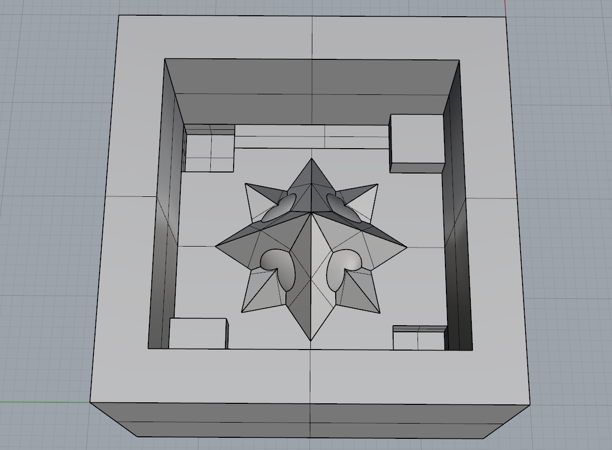
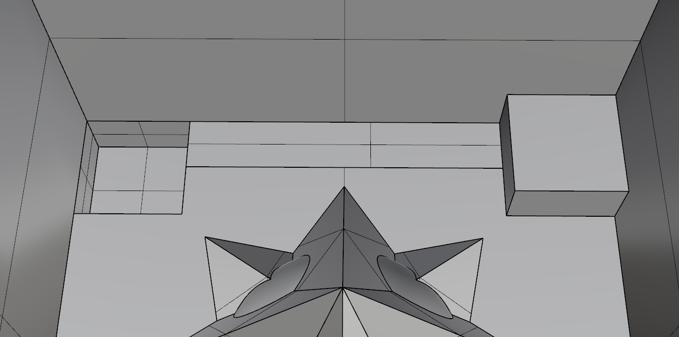
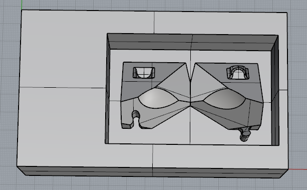
Note: This was the final design produced in 3cm³.
I had some design problems, so these are my considerations:
- make a mold of the material used (machinable wax) to preview the size of the design on the real scale
- draw/preview the mill to see the real size to avoid impossible spaces to enter in (mill thicknesses/heights, collet…)
- consider the round shape/radius of the mill in plane/surface changes
Process
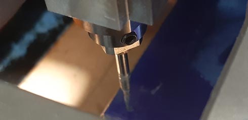
In this case, Roland monoFAB RLM-20 precision desktop milling machine was used on machinable wax. Also, a previous test of the design was made with the same machine in ___ foam in order to test the definition and final result of 3 mm / 1.58 mm mills.
5th week (electronics production)
(check it to see Roland monoFab RLM-20 procedure).
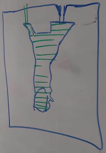
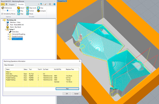
- The milling file
I used RhinoCAM in Rhino 5 to generate the code for the machining. The main steps were:
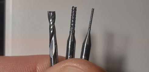
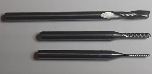
- Parallel rough > 3.175 mm mill
- Parallel finishing > 1.58 mm mill
- Parallel finishing (90 degrees) > 1.58 mm mill
- Parallel finishing > 0.79 mm mill
-
Horizontal finishing > 0.79 mm mill
I also tried to generate the first model on fabmodules.org:

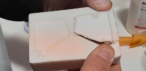
I tested in foam my first design and I encountered these issues:
- joints in the design were to small to the mill to cut into it
- design depth was too much to the mill to reach the bottom without compromising machine and material parts
I changed many times the 3D model and, finally, I decided to use my backup design to avoid wasting time and material.
After some problems with the collet fixing screw of the milling machine, I could mill my design fast and without any inconvenient.
2. MillingFoam milling test:
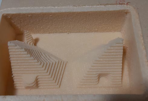
This test helped me to clarify if the milling file on wax milling would be ok. I was worried because of the non 100% reliable RhinoCAM simulation on small parts. Fortunately, I realized that I have to change my 3D model to ensure the correct milling.
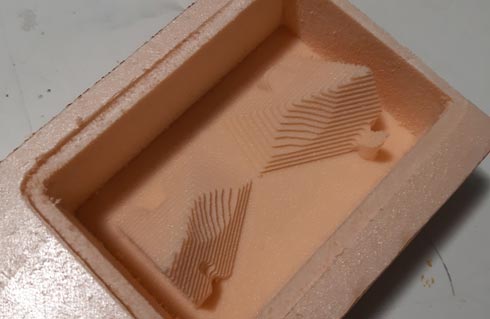
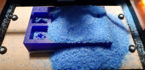
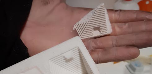
Anyway, this foam mold was a good excuse to try textures and the non-stick release agent product.Wax milling:
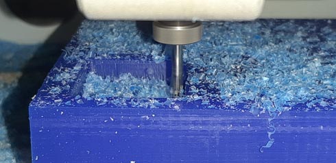
3 mm rough job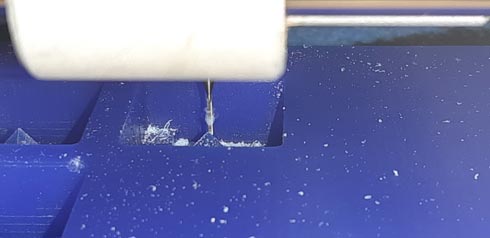
0.79 mm refine job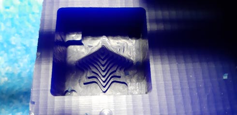
3 mm rough job result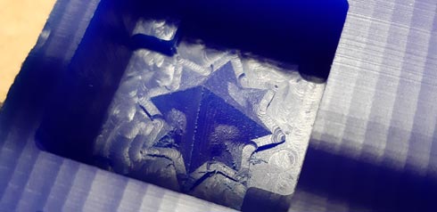
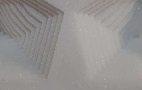
1.58 mm refine job result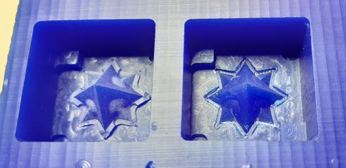
1.58 mm (left) VS 0.79mm (right) refining jobs comparisonNote that there is no big difference between them
I made the same design in a bigger size:
-
Casting
-
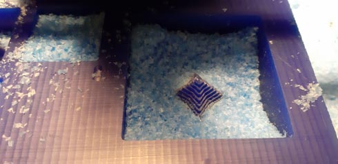
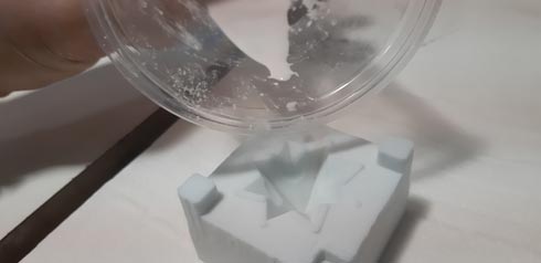
Silicon casting:
Mixing
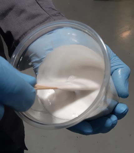
Mix proportion: silicon (95%) with catalizer (5%)Pouring
Avoiding bubbles
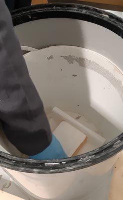
Extracting bubbles
Curing
The pieces were ready (curated) about 5 hours later
-
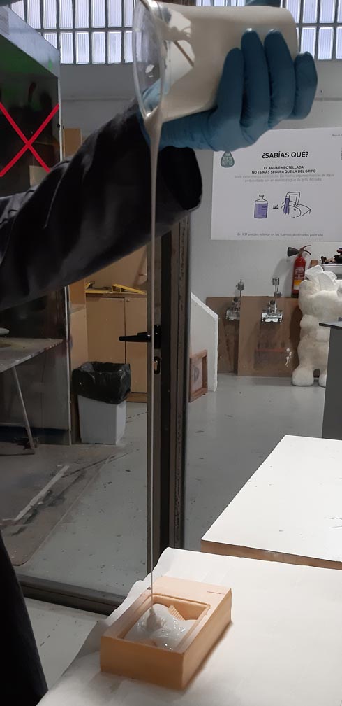
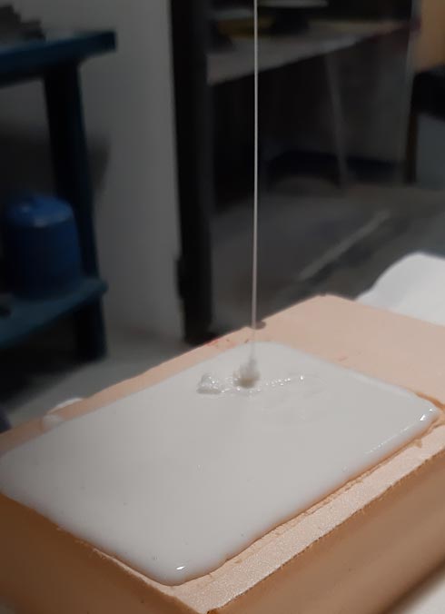
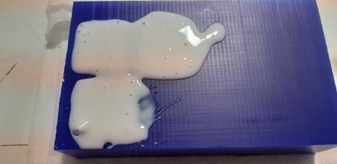
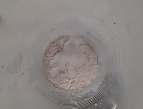
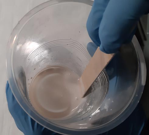
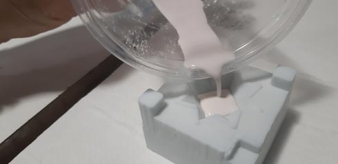
Resin (Acrylic polymer) casting
Mixing
Mix proportion: 1:2.5 (liquid:powder) proportion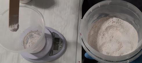
Pouring
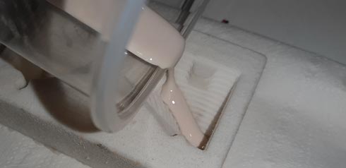
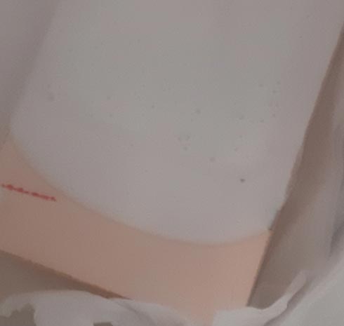
Curing
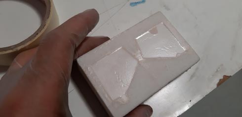
The piece was ready (curated) about 30 min later
Exercises
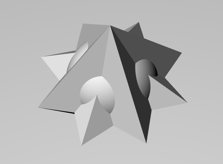
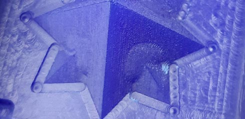
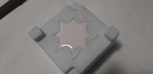
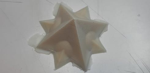
Star exercise
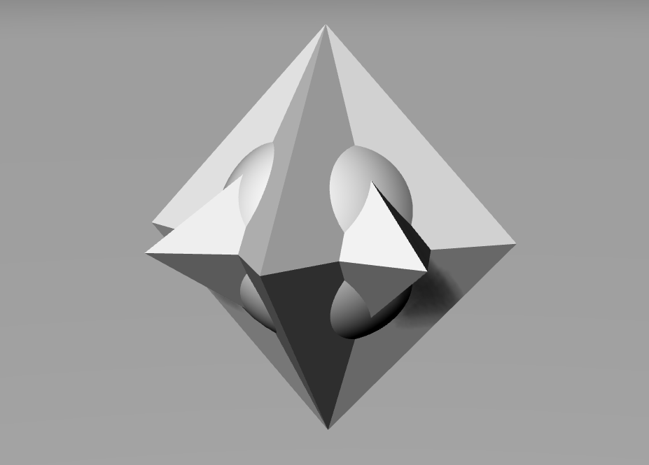
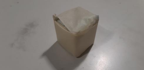
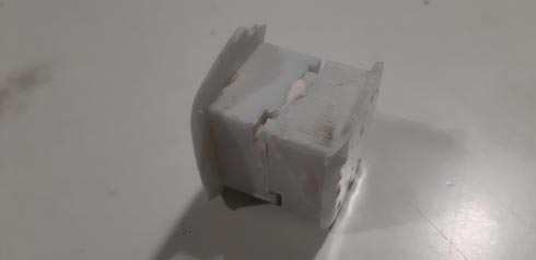
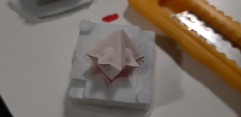
Tiny star exercise
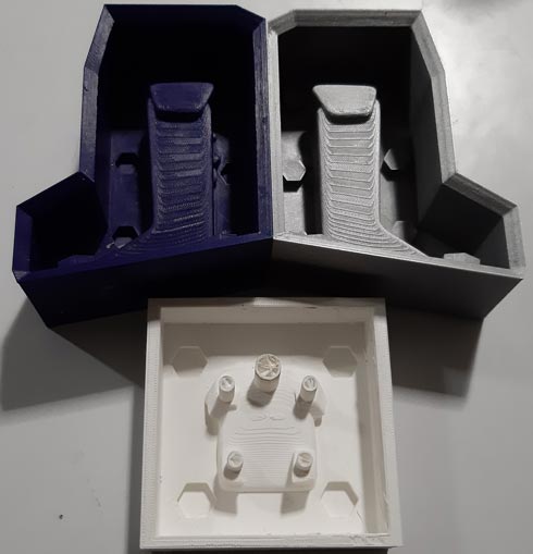
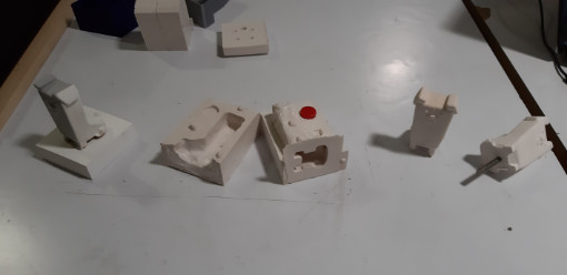
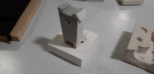
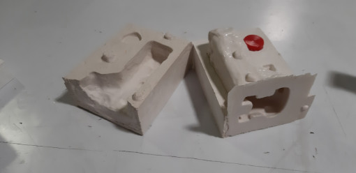
Results
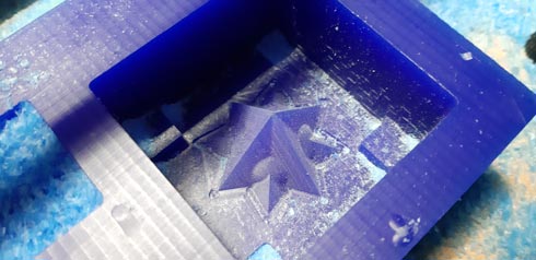
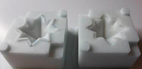
First molds (foam and wax) and contra-molds (silicon)
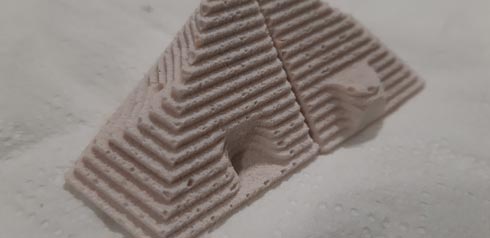
Foam texture on silicon mold
Tiny molds
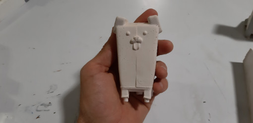
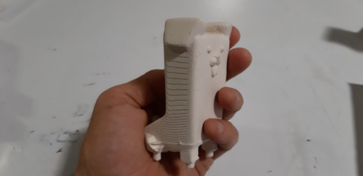
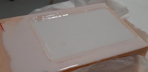
Foam resin result
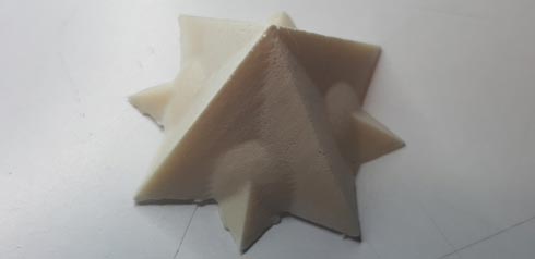
Star resin result
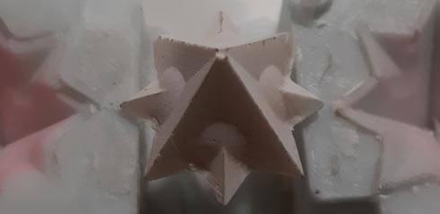
Tiny star result
Problems
Foam broken mold
Collet screw
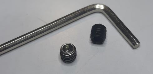
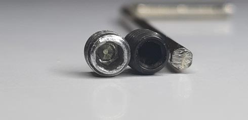
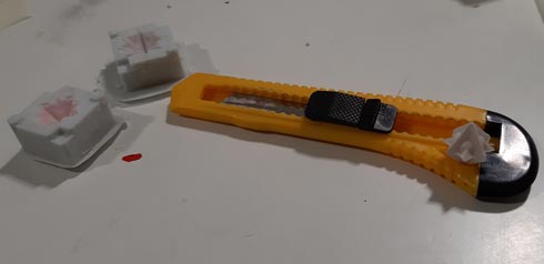
I had problems with the milling machine screw that fit the collet. It was worn, so I had to go to buy another one to replace it. This delayed my job.
Crayons/Candles try
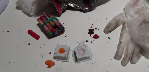
I tried to melt crayons and wax for candles. Crayons were bad, so they broke so easily. Candles are pending.
Original files
- Machining > (machining - use Rhino 5 or 6 to see the machining jobs in RhinoCAM)
- 3D files > (stl)
- GCODE > (only Star design)