8. Computer controlled machining
This week I worked on 2 main tasks on computer-controlled machining in order to familiarize with the ‘possibilities of CNC machining > drill, pocket, dogbones, nesting, etc.‘. These were the assignments:
-
Group assignment:
test runout, alignment, speeds, feeds, and toolpaths for your machine
(Follow this link to see the group assignment) -
Individual assignment:
make something big
SUMMARY
-
Have you?
1. Explained how you made your files for machining (2D or 3D) > DONE
2. Shown how you made something BIG (setting up the machine, using fixings, testing joints, adjusting feeds and speeds, depth of cut etc) > DONE
3. Described problems and how you fixed them > DONE
4. Included your design files and ‘hero shot’ photos of final object > DONE -
PENDING TASKS
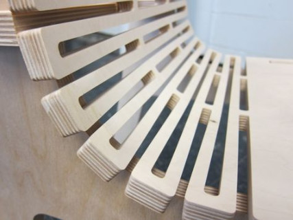
1. I would like to try Curve-bending (living henge)
~~2. Pocket~~
ASSIGNMENTS
Group - Test machine
About Computer controlled machining
CNC (Computer Numerical Control) machining is a subtractive manufacturing technology: parts are created by removing material from a solid block using a variety of cutting tools.
The material removal mechanisms have significant implications on the benefits, limitations and design restrictions of CNC.
CNC machining is a digital manufacturing technology: it produces high-accuracy parts with excellent physical properties directly from a CAD file. Due to the high level of automation, CNC is price-competitive for both one-off custom parts and medium-volume productions.
(Source)
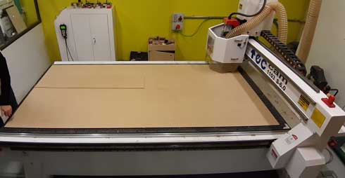
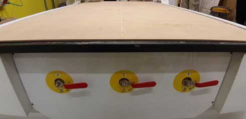
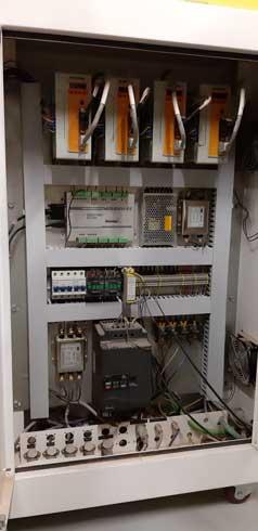
Machine description
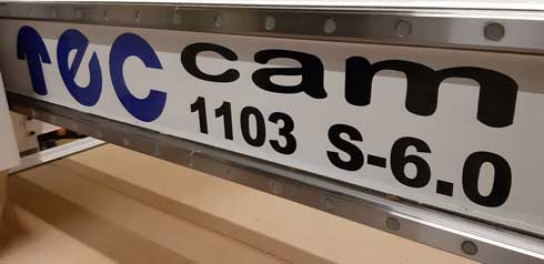
The TECH we used to do the assignment is a TEC-CAM 1103 S-6-0, which basic technical data is this: (Source)
| Functions | Parameters |
|---|---|
| XY working area | 1.300 x 1.200 - 1.300 x 2.500 - 1.600 x 3.200 - 2.000 x 3.000 mm |
| Z Axis clearance | 180 mm |
| Repetibility | ± 0,025 mm |
| Resolution | ± 0,02 mm |
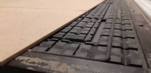
| Working surface | Vacuum table with pockets (optional T plates) |
| Structure | Welded steel beams |
| X-Y Axes Movement | Helical rack and pinions, linear rails |
| Z Axis Movement | Ball screw |
| Max. Travel speed | 50 m/min |
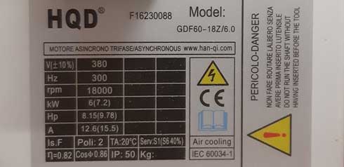
| Spindle power | 6kw - 18.000 rpm - air cooled (ER32) |
| 3kw - 24.000 rpm - water cooled (ER20) | |
| Voltage | AC380, 50-60 Hz, 3 ph |
| Interface | USB |
| Vacuum | Side channel turbine 5,5 kw / 7,5 kw / 11kw |
| Software | EnRoute / VCarve |
| Weight | From 1.500 kg, depending on dimensions. |
The CNC router machine TEC-CAM Series 1000 includes high-quality components.
The CNC router can be provided with a step motor or a servo motor. The X and Y axes use a helical rack and pinion traction system that ensures a higher speed with lower noise.
(Source)

(Follow this link to see the machine features)
These are the recommended materials:
It can cut and engrave a wide range of materials, such as:
- Methacrylate
- PVC
- MDF
- Solid Wood
- Aluminium
- Copper
- Brass
- Porexpan
- Foam
- etc.
(Source)
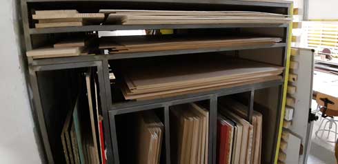
Material description
For this assignment we used MDF: 10mm thickness / 2400*1250 mm .
Medium-density fibreboard (MDF) is an engineered wood product made by breaking down hardwood or softwood residuals into wood fibres, often in a defibrator, combining it with wax and a resin binder, and forming panels by applying high temperature and pressure.
MDF is generally denser than plywood. It is made up of separated fibres, but can be used as a building material similar in application to plywood. It is stronger and much denser than particle board.
(Source)
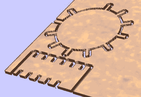
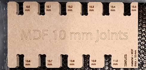
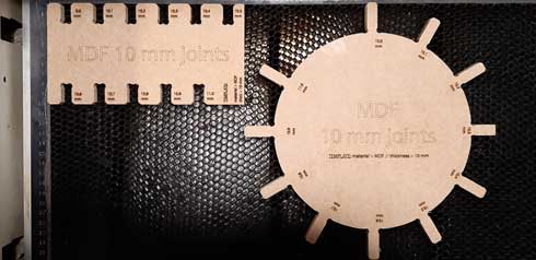
Design description
I designed this tolerances system in Illustrator for testing the CNC machining:
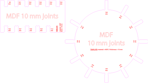
The idea with this design is to test the capabilities of MDF 10 mm to fit with more or less resistance, and with/without the support of glue between the joints. I also made the same design for PLYWOOD 15mm (see Original files).
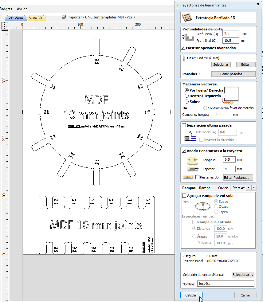
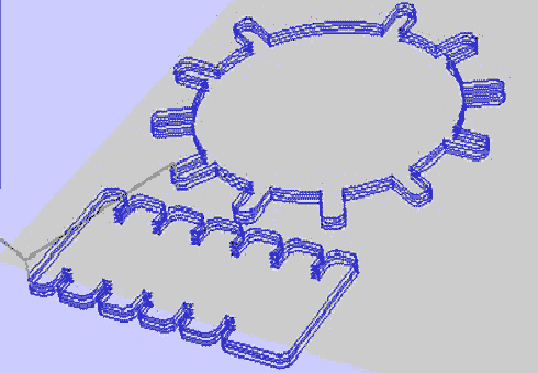
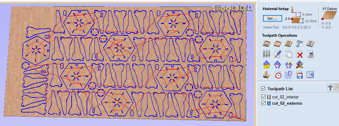
These are the CNC machining settings in Cut2D Pro to cut the design: (see screenshot)
- Define workspace (similar to the material dimensions) > 1250*2400 mm
-
Define material (MDF) > Thickness: 10 mm / Tool coordinates and security movements
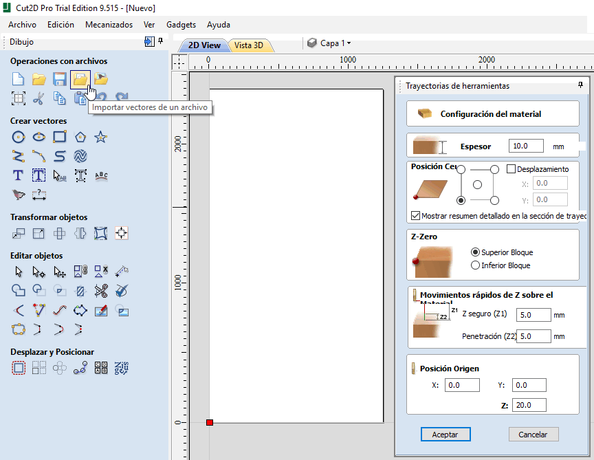
-
Import vectors to cut and prepare them before the job selection (dog bone fillets = mill diameter)
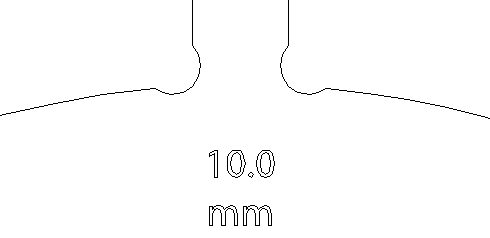
The Fillet tool in Cut2D Pro is very useful and makes the fillet task faster than designing them on the drawing software. Anyway, the way to draw this fillets ‘by hand’ is this:- draw a circle with the diameter of the mill
- move it putting its center on the corner where you need to obtain the fillet
- move it in 45 degrees restriction to the interior of the shape until the corner and the circle intersect
- combine both shapes with a drawing tool (such as Illustrator > Pathfinder > Union)
-
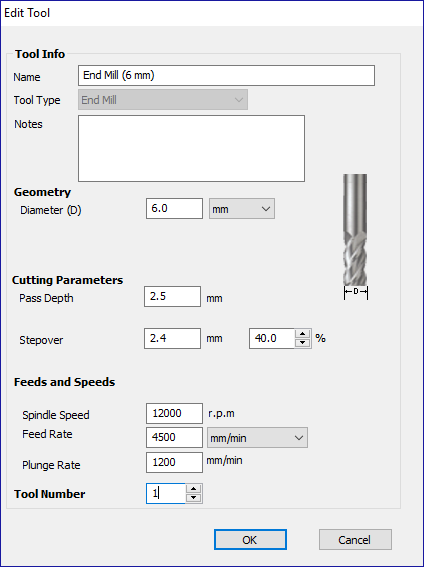
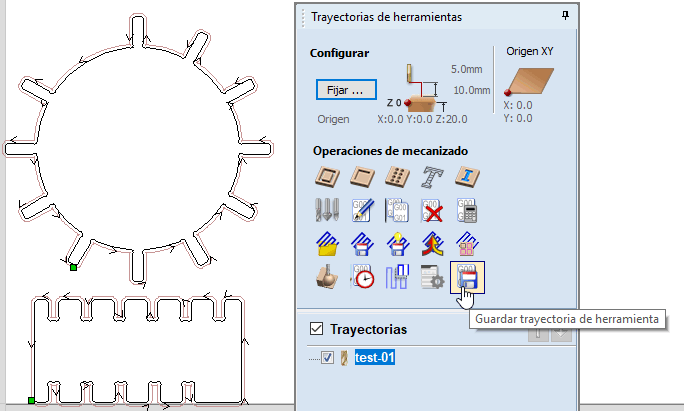
Prepare cut job (Profiling) > Cut depth / Tool / Vectors interpretation / Tabs / Name / Calculate
I’m not sure of this, but I think that the software automatically discards spaces between vectors that are smaller than the mill size, so they will not be processed as part of the job.
Anycase, ensure to delete/move_to not used vectors of your drawing (such as text, numbers, etc…) and select the ones that correspond to the type of job in mind. It’s possible to separate vectors by layers.
Also, create a jobs ordered list to process them separately. Remember the queu general rule: engrave > incut > outcut
5. Simulate, check and reset any needings
This job was cut in 3 minutes (aprox): 
- Save to .tap file jobs you want to process
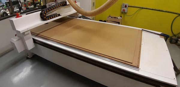
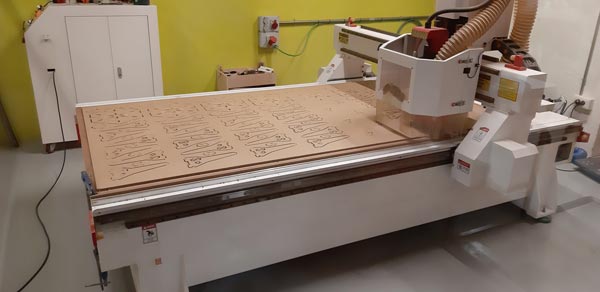
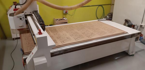
Process
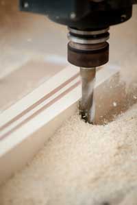
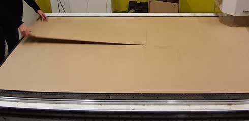
These were the followed steps to cut the design:
- Review material > Regular tickness (no moisture, hits, glues… that could deform the material, bringing problems with Z routines)
- Prepare design > CNC MDF test template > MDF 10mm
- Prepare .tap file(s) > I used Cut2D Pro to generate the g-code
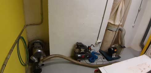
- Prepare materials in the CNC machine > The vacuum system ensure the material stayed in place
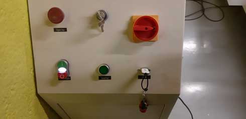
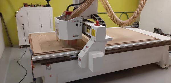
- Prepare the machine.
- Power on and switch on the vacumm system and the dust extractor
- Calibration
Machine’s calibration must be made at the beginning because of the priority and the importance to make it before wasting time and material. The way the machine works needs a bed well calibrated to avoid Z distance differences. - Origin
Job origin must be set at the beginning because of the needing to put X, Y, Z space references between the g-code and the CNC bed. By this way, the job is safe to be made correctly without space errors that could bring undesirable results for both the machine and the design.
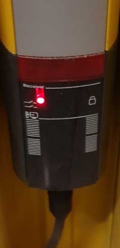
- Load file to CNC > USB pen-drive
- Test operation > Watch/Hear if job is been done at the selected velocity, and hear if the process doesn’t sound rare and forced. If needed, warn experienced people and stop the process.
- Check operation and first results
- Readjust, if needed, machine’s settings/material/design/CNC machine file(s) > If material or CNC are changed, machine’s/material’s preparation must be done again
- Start the reviewed job
- Watch the job all time and wait it to be finished
- Clean PROCESS DEBRIS on the machine and parts
- Secure the workspace (turn-off the machine, close door, …)
- Check final design results > ADVICES
- Manual post-processes, if needed
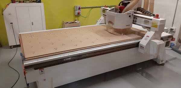
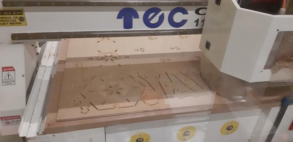
Results
This is the final result of the first attemp (pieces cut at the board):
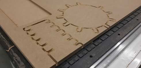
Note that not calculating exactly the dimensions of the design and the position on the coordinates origin, could end on problems, bigger when you are working with so powerful machines like CNC.
After the CNC machining job, I used the laser machine to put the different values on the pieces.
Individual - Make something BIG
The idea with these designs is to ‘demonstrate 2D design development for CNC production and to describe workflows for CNC production.
Design description
-
Research
These were the main principles to follow when imagining my design:- make something big (that justifies the CNC machining process and that fits to human scale)
- make something useful
- make something resistant
- make something stable
- make something easy to manipulate
- make something that includes joints, engraves and wood bending
- make something simple
- make something scalable
There were many designs rounding in my head for making something ‘big’ (something as our human scale and that justifies the CNC machining use). There are some of my ideas:
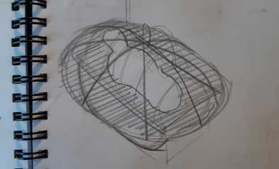
Baby crib
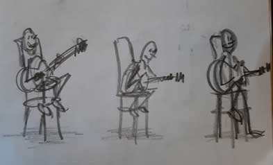
Musician chair
Chairs, tables and joints
Garden bank and final idea
With my starting ideas, I researched by the www in order to inspire a little more, and I’ve found a lot of things that made me think that maybe it finally wasn’t a good idea because ot the huge brainstorming :^s. Here I put a few of the lot that I saved:
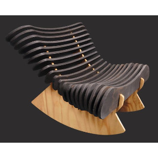
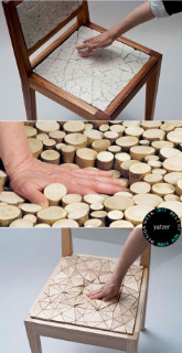
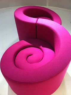
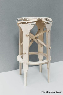
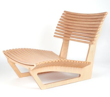
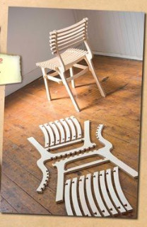
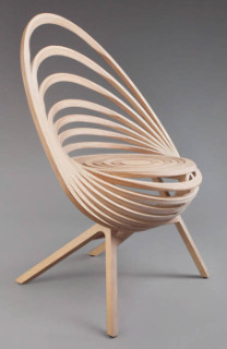
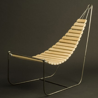
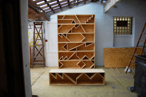
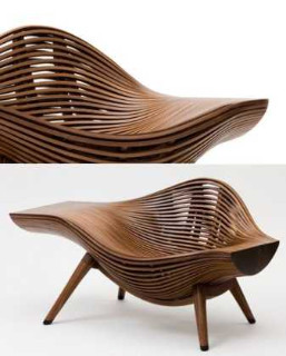
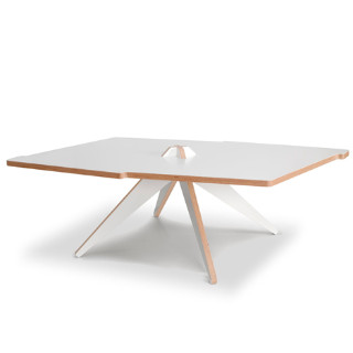
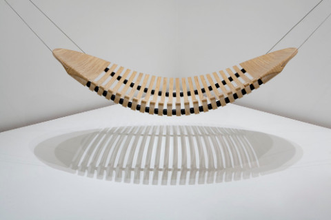
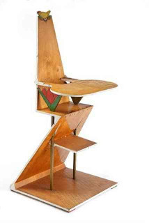
(Credits: Rietveld, Bae Sehwa, Adam Cornish, Estampille 52, Eins Design, RO/LU, Elemento Diseno,… many credits remains here, which is a hard task to do…)
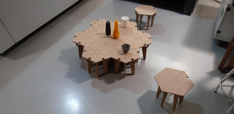
I thought then in paraguayan (and south-american) customs of meeting to share with mate or tereré, which is something usually done near the ground:


EveryONE drinks! PRRAAAK!!! (free the parrots!)
-
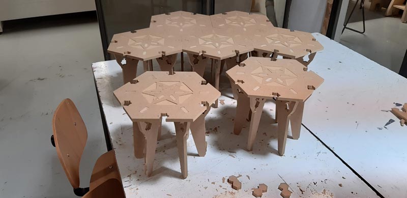
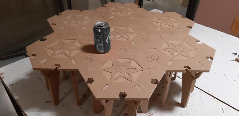
The design itself
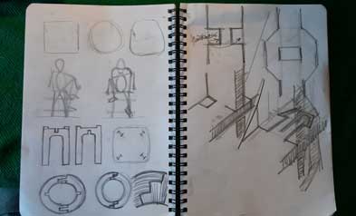
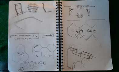
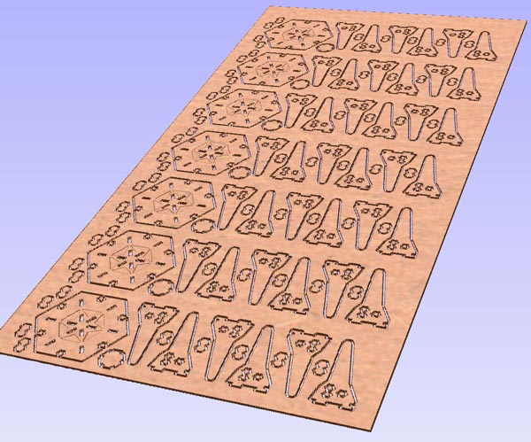
Then, I thought that I could made something modular to adjust to these different social settings, so I began to play with hexagon (as it’s a shape that includes the power of isosceles triangle, the partial capability of square matrix and the proximity to the circle to avoid hard corners) and the number 9:
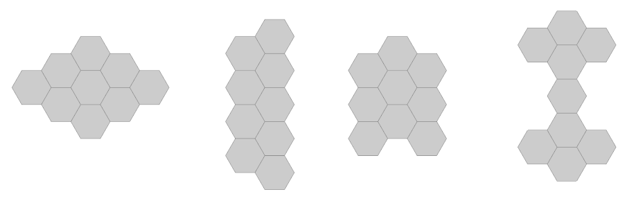
Tables and beds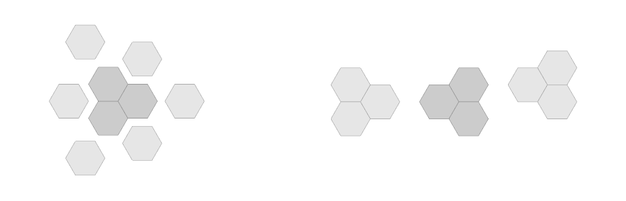
Meetings #1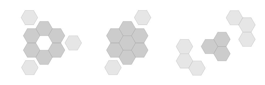
Meetings #2I used Illustrator to technical draw the vectors of the module with the help of guides, colours, layers and the ‘Pathfinder‘ tool.
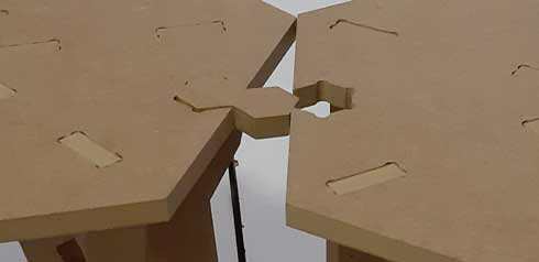
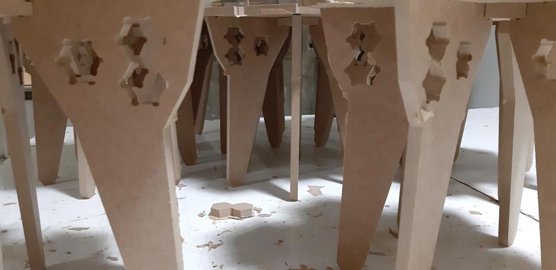
As shown, the idea to connect modules is to use a little piece ‘extracted’ from one of the 6 chair-table supports. That hole also allows to easily pick up and move the module with the hand.
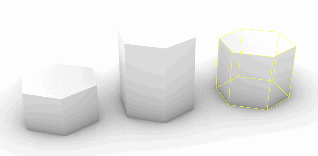
Another advantage is that, as modules are small, you can operate them with feet, avoiding you to get down for that purpose. These are some captures to figure out the size restrictions in order to mantain the result between stability and human scale: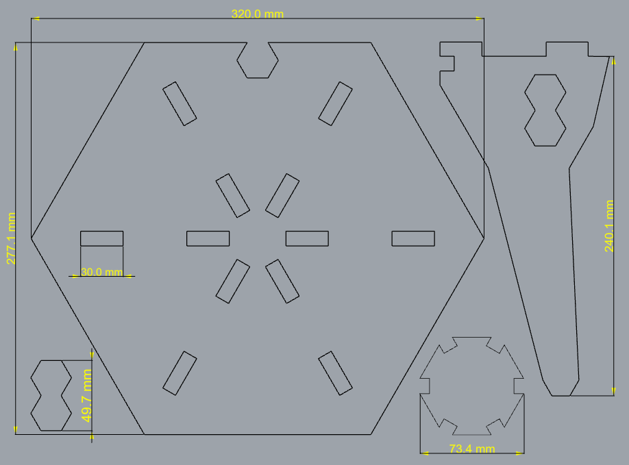
Jobs in Cut2D Pro used the same settings as in the group assignment, with the exception of the number of jobs. In this case, I made a diferrence between interior and exterior cutting.
-
UPDATES:
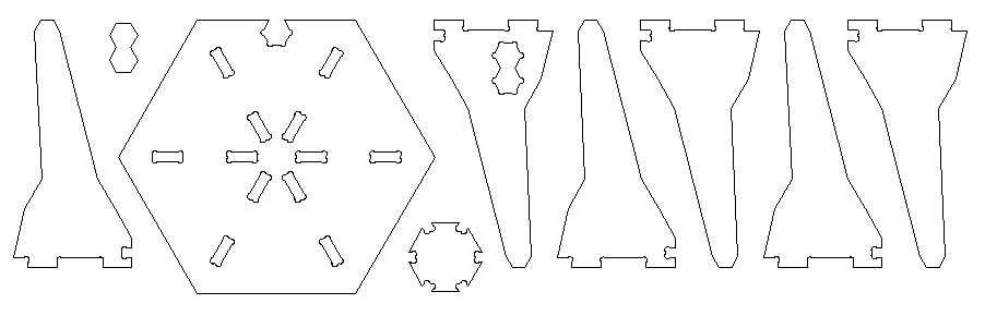
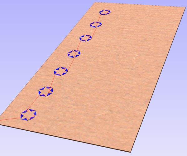
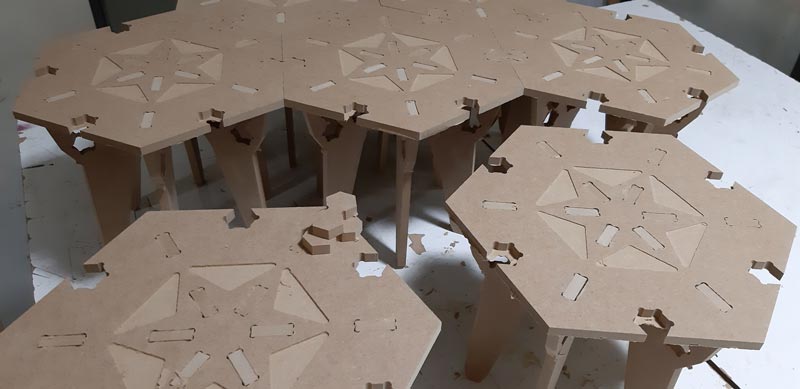
This is the final design, including more joints and pockets on each piece, and also the supports have an additional hole for simple hexagons that could be made on lasercut if it is preffered to close the shapes on the external limits.
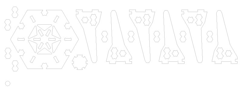
The left bottom circle was used to separate the pieces on a security distance of 22 mm for the milling process
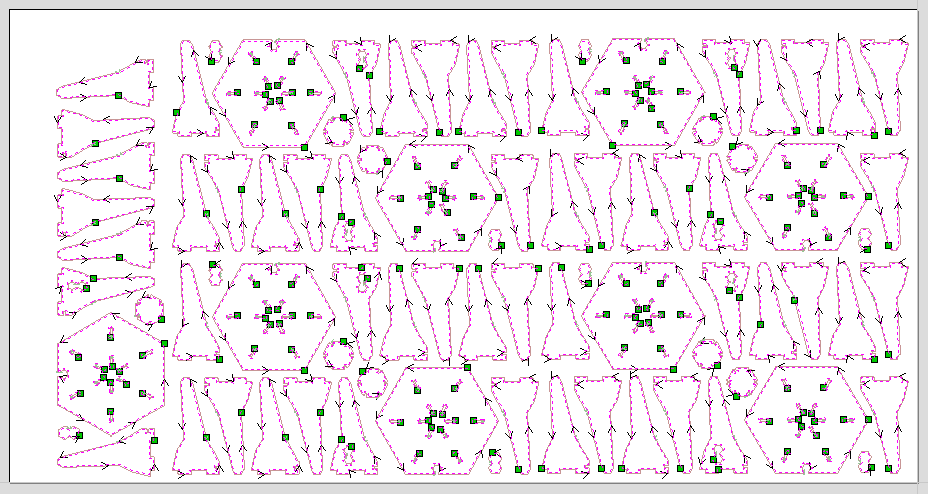
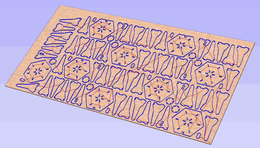
These are the machining captures updated:
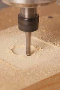
Pockets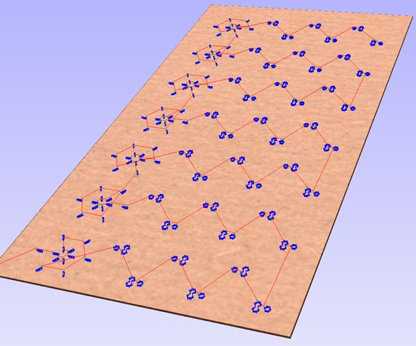
Incuts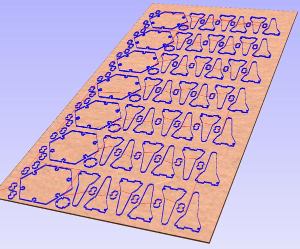
Outcuts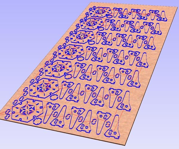
Whole machining
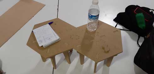
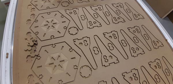
Results
This is the final result of the first attemp:
-
Details to afford:
-
Design:
- each module must have more group joints
- design must be parametric
- design could be bigger (with another material)
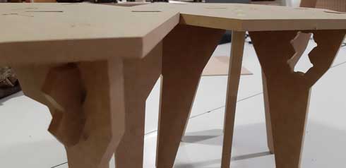
- supports may could give more stability
-
Cut:
- ‘review twice, cut one‘ (infill made me repeat…, review 3, 4, …)
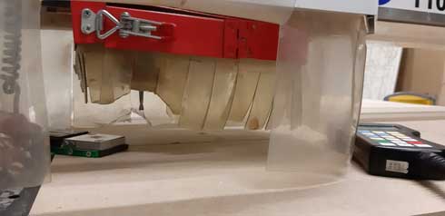
- kerf-bending and pocket jobs are still remaining

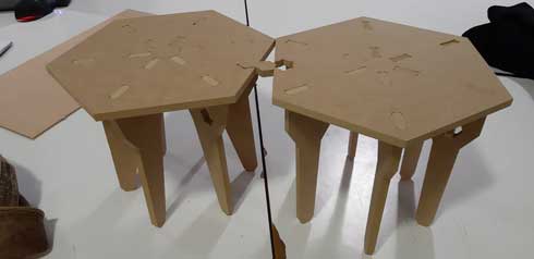
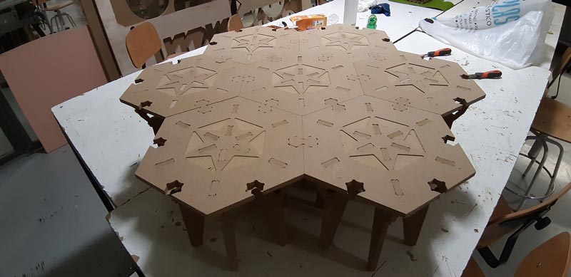
Although the isolated module seems a smurf chair, the idea is to allow multiple bigger combinations… -
-
UPDATES:
This is the final cut process:
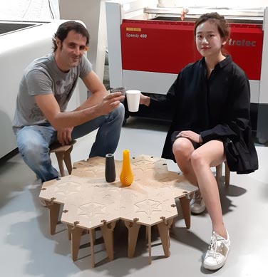
And these are the final results:
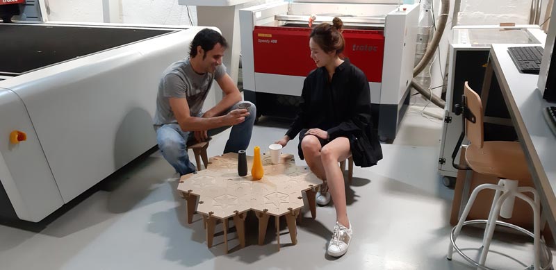
PLA party
Conclusions
Illustrator / Cut2D Pro and TEC-CAM 1103 S-6.0 on 10 mm MDF report these main pros/cons conclusions on Make something big:
• PROS
- CNC machining is a very powerfull process and allows to reach final results directly
- previous tests ensure a great precision on joints, avoiding extra work
- a lot of knowledge is on the web to get deep into the topic
• CONS
- 10 mm MDF was a restriction for making resistant objects
- CNC machining experience takes a lot of tests and time
Original design files
- CNC test templates MDF-PLY > MDF 10mm / PLYWOOD 15mm
- Design >
- HexSocial v 1.0 (vectors and cut parameters)
- HexSocial v 2.0 (vectors and cut parameters)
WorldWideWeb
Learning
Documents
- Student CNC Guide
- Fundamentals of CNC Machining
- Xometry DesignGuide CNCMachining (*summary)
- Machining operations and machine tools (*images)
- Digital fabrication: Joints
Links
- An introduction to CNC machining (*workflow)
- Basic CNC: Machining wood
- Vitesse et Avance: Trouver le Point d’Equilibre pour Usiner Bois et Plastiques
- CNC machining: The Complete Engineering Guide
- Basic Manufacturing Principles
- CNC Panel Joinery Notebook
Video
Resources
- Cut2D Pro
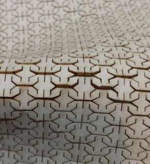
- Living hinge patterns
Credits & Others