Try the complexity because the machine can take it
The laser and the vinyl cutter are two machines that can be creative on the type of material we use in it and the effect that it creates. We can do 2D or 3D with a very high precision. Now: How can we think a little outside of the box and try to do complicated stuff?
Challenge for the laser cutter
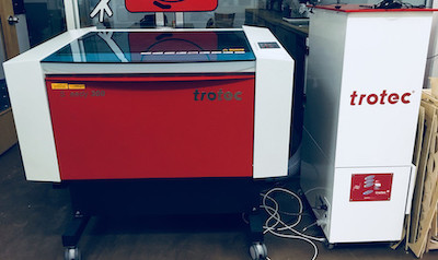
The laser cutter is a machine with a laser beam and a gaz (CO2) that together melt the material with a high pression to allow you to engrave, cut or mark the material. We use a Trotec Speedy 300 to do this assignment of the week combined with the software Job control to communicate to the machine. The extension of this software can be accessible from Inkscape a like a big plotter. Job Control can attribute parameter at 16 specific colors so you can control the order of the jobs, and put different settings for a specific job.
There are few things to know before doing a job:
- The material type and the thickness influence the parameters of the machine (power, speed and pulsation of the laser)
- The precision of the focus influence the esthetic and the precision of the cut
- The maintenance of the machine influence the precision of the laser, the color of the smoke who can stick on you final piece and the air quality around you. If the filter is not changed often, a bigger amount of smoke can stay in the machine and then go out and put more volatile organic compound in the air that you will breath after.
- The type of material that you are working with react differently with the laser and influence the result of the cut and the finish. For example, the acrylic cast have a better reaction than the acrylic extrude.
Vectorise file
Trotec Speedy 300
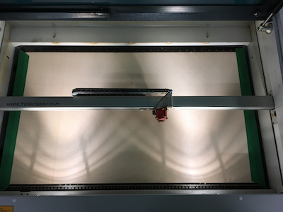
Put your material into the laser machine.(If it bend, use tape to make it flatter)
Position on your drawing in Job Control
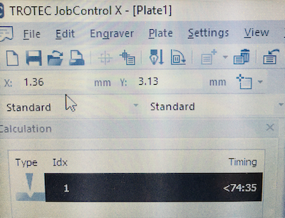
Position of your laser in Job Control
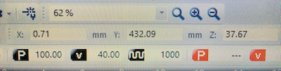
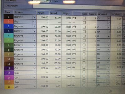
Here are your parameter
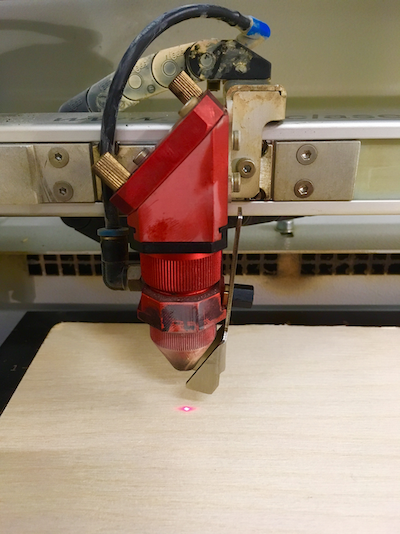
Make your focus with the tool reliated to your lens
Engrave, enjoy and if happen anyting, press pause
To use the laser cutter
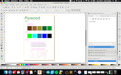
- Create a vector drawing (the machine will follow the mathematical path and not the esthetic path). I created a sample test drawing that I can test different parameters
- Send it to Job Control like a normal printer.
- In Job control, slide your drawing into the main space.
- Double click on your drawing in the main space and attribute parameters to the color.
- Start the machine and his ventilation
- Connect the machine with your computer with the physical USB wire and with the virtual logo USB at the bottom right of the screen.
- Make your laser focus on your material and place the head of the laser were you want to beggin you job. You can also put coordinate to place your drawing of your laser head. It’s very useful when you do a double side job.
- Start your job, watch it and if anything happens you can press pause.
For this week I will make a press fit structure. For that I will need a parametric tool to test the press fit thickness of my material and design parametric part that we can change easily depend the material we use.
Challenge for the vinyl
I take the opportunity of the vinyl assignment to explore the fonction trace bitmap on Inkscape. I will check how delicate the texture can be on the vinyl cutter and if it's possible to put few layer of differents vinyl colors on top of each other to create a delicate and artistic image.
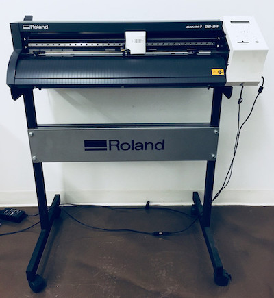
At the lab we use the GS-24 Rolland vinyl cutter. The vinyl works with 3 principales parameters, the speed, the force apply and the offset blade. Here is the Cutter blade reference guide to know some basic parameters to cut material. We can cut vinyle, paper or any material lookalike.
How to
1-Parametric tools
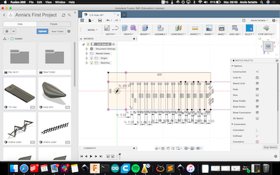
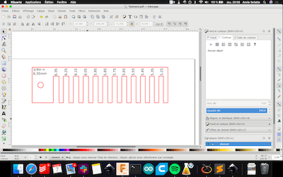
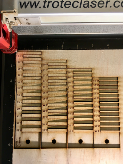
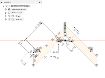
- I draw on Fusion 360 a ruler in the form of a comb with the maximum space of ¼ inches or 6.35mm. Then I link that dimension with the other spacing, reducing it of 0.10mm by spaces. I put 12 spaces by ruler and the next one, I just change the first dimension and everything change in the same time. (see pictures)
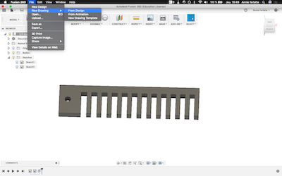
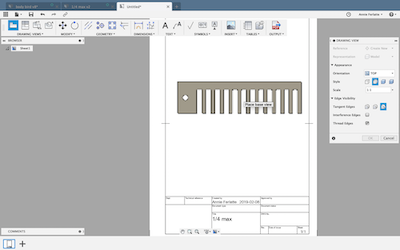
- I make a technical drawing of the top view of each ruler and export it in PDF.
- I import it in Inkscape, delete the template of the technical drawing and add the written dimension on each ruler.
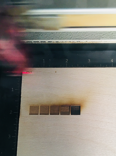
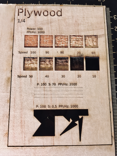
- I create a test sample on Inkscape that I can use over and over to test parameters on differents materials. I cut it on the laser cutter with the same wood that I will do my press fit ruler
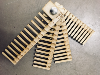
- I choose my parameter and cut the press fit ruler on the laser cutter. I assemble every pieces and the first part was done.
Sketch of the tool with the parametric dimension
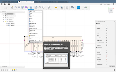
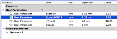
Where to add or change the parameter
Create a new drawing from the design
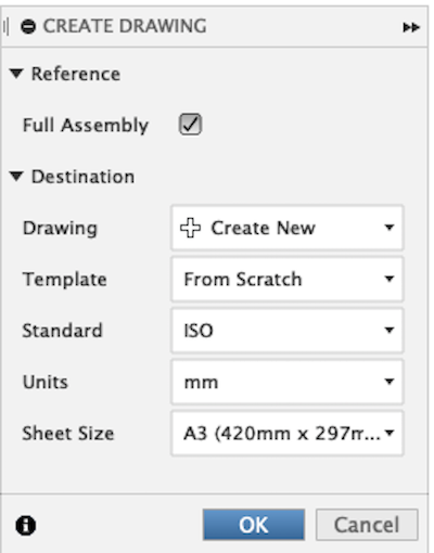
Place your object and chose your scale and finish
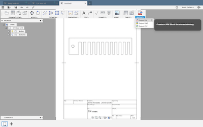
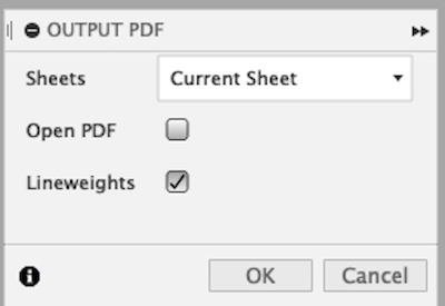
Export in PDF
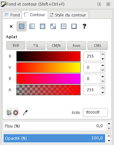
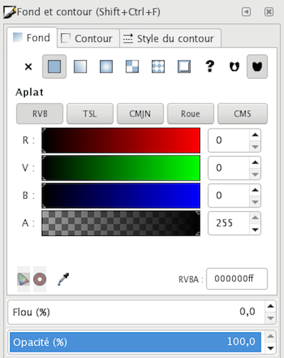
Open with Inkscape and add your laser cutter color and detail like the text
Do a sample test parameter on the wood you will use
Cut the ruler on laser
Assemble all pieces
2-Press fit structure
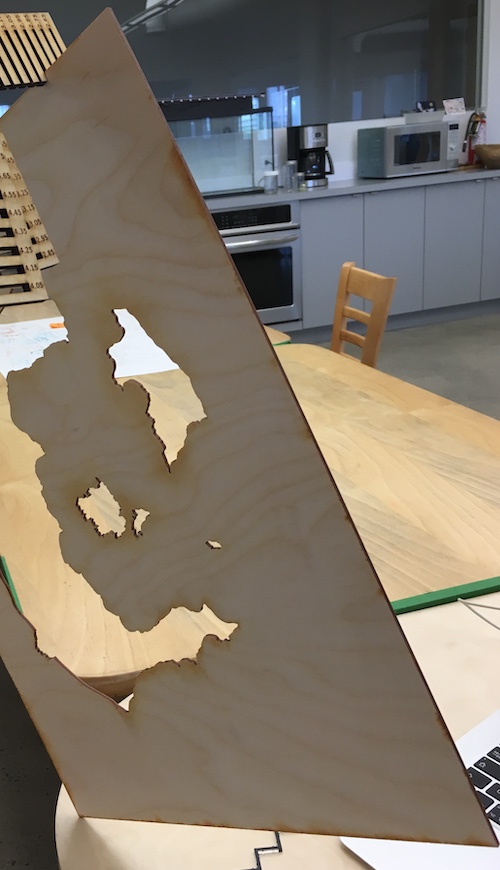
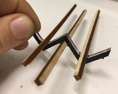
- I design my different pieces on Fusion 360. I was really inspired by the student Kurina Sohn. She tested differents pattern with textile, but I was wondering if it is rigid enough for that kind of mouvement it would create.
- I created then a technical plan of each of my pieces and export it in PDF.
- To find the kief I use the tool I made and try to find the tyniest thickness space possible. It was 2.95mm.
- I imported it in Inkscape, put my different colors on (no fill, with a stroke path for cutting or marking and no stroke path with a fill for engraving)
- Laser cut everything on wood and acrylic
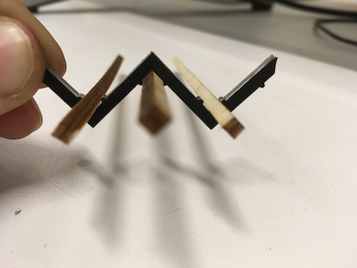
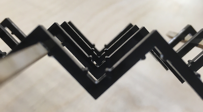
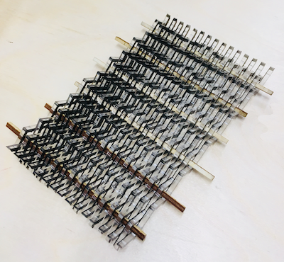
It is pretty much the same process as the creation of the tool but with another drawing. The thing is interesting in that structure is the little acrylique bump who hold everything. The problem I got is when I want to put alot of these acrylic section, the wood stick bent too much so it is very delicate to made everything hold toghetter. I can, in the future, make some improvement replacing half of the circle by a angle so the wood stick can clip and be stedy.
Try to find the smallest gap that the thickness of the material can fit.
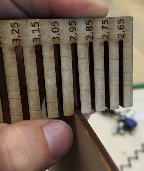
So tight I can lift the material
Sketch on fusion with parametric dimension
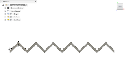
Miror fonction on fusion allow you to put the quantity you want
Parameter on Job Control
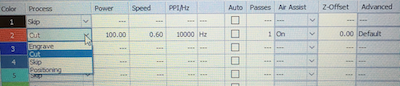
First test almost cut, it seem that it stick toghetter. I did it again with 5000Hz and it was good
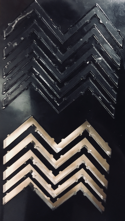
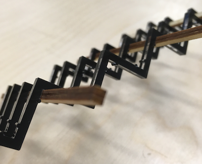
First test working
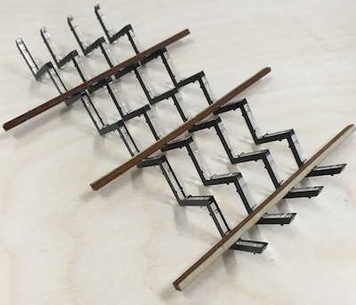
I cut some bigger one

3-Vinyl cutter
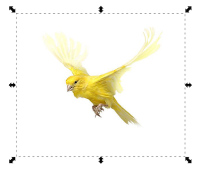
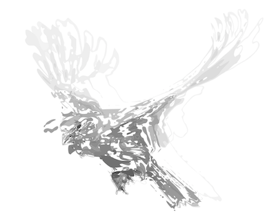
- Import a image from internet.
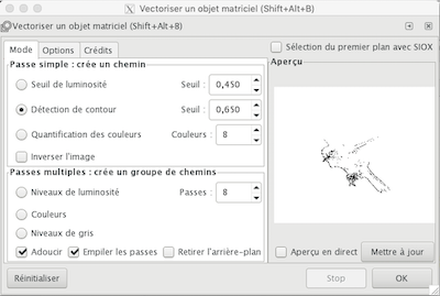
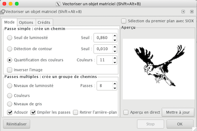
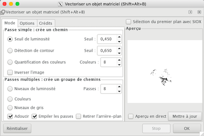
- Select your image and select vectorise the path.Play with the different technics and tolerence of it.
- You will rapidly have great result.
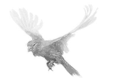
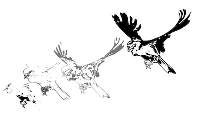
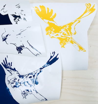
- I choose 4 vectorised results that I align perfectly one on top of each other. (it is gray and black)
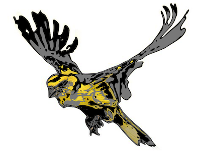
- I put similar color of the vinyl I plan to take to visualise.
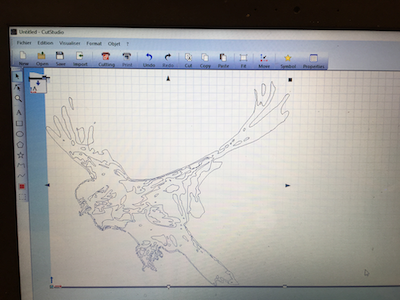
- Click on extension, Rolland cut studio and we enter in this sofware who communication to the vinyl cutter.
- When you click on Cutting you can change the parameter of your machine
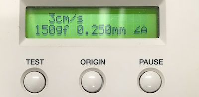
- I start with:
- Force: 150g/f
- Speed: 3cm/s
- Offset: 0.25mm
- This parameter is too heavy. It did some hole in my paper or the delicate pieces of the vynile was flippin in the air. I check the cutter blade reference guide to help me find basic cutting parameter and with the one they suggest it was perfect
- This parameter was perfect for all of my vinyl:
- Force: 100g/f
- Speed: 3cm/s
- Offset: 0.25mm
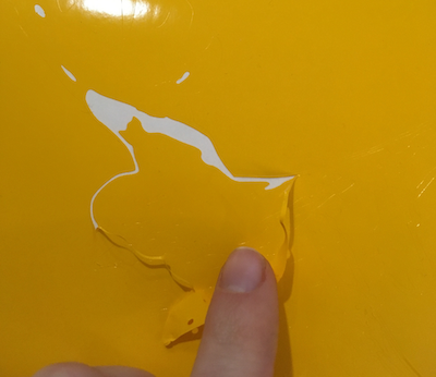
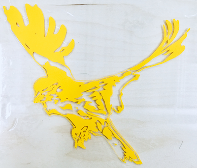
- Cut all your pieces you need and than start peelling. This job is long, but delicate hand can do very small details. One of my goal is to check how small can we can go with that machine that habitualy do builky job. It took me around 2 hours to peel everything. This is why I made some test of peeling before to verify my parameters. Everything need to be very well cut to let me have a chance to peel the smallest dot.
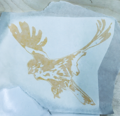
- After you can put some transfert paper on your vinyl stiker and rub to make everything stick.
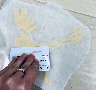
- When you apply it on your final surface, glide a hard card on it to take off the air bubble in the same times.
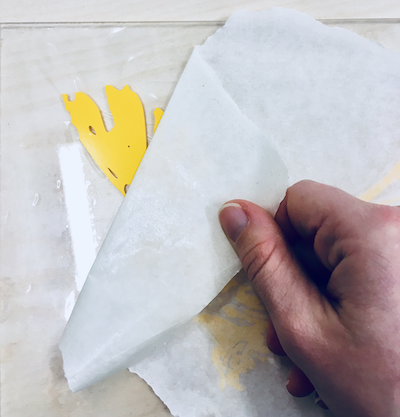
- Slowly take off the transfert paper. Don't lift it in the air but follow the surface. Closer you will be to the surface better it worked.
- Repeat for all layer. Here's a tip, if you have difficulty to align your layers, you can make some holes in strategic places to see under it in the same time you put the other layers.
Import in Inkscape your picture
Variation of different technic to vectorise a object
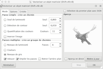
Result for the technic gray level
Result of the other technic one on top of each other

Sending the file to Rolland cut studio
Rolland GS-24, vynile cutter
Parameter for cutting, my first try
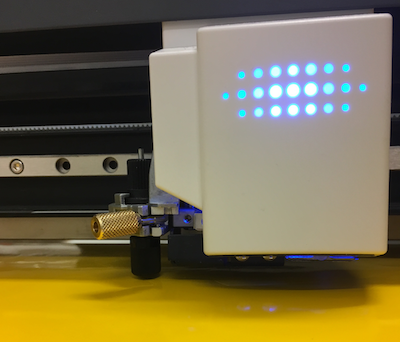
Cutting on the vynile
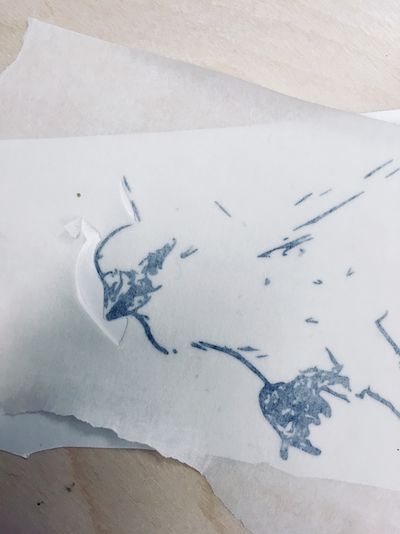
Peeling test
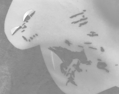
All pieces peel
Put some transfert paper on the work
When you stick the vinyle on your final surface, use a hard card to take off slowly the air bubble
Take off the transfert paper
Result for the 1st one
To help you aline the next layer, you can make holl on strategic places to see under
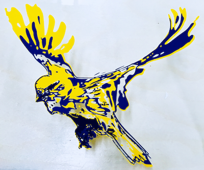
Here is the final result
The moral of this story
Computer controlled cutting is pretty similar on each machines. It follows a path with a parameter that influence the tools that it uses. Blade or laser, the main idea is very similar, but the effects are completely differents. We can create 2D or 3D volume without a problem, it's very versatile. Files
Contact
Annie Ferlatte
ferlatte.annie@gmail.com
Montreal, QC, Canada