14. Networking and communications
This week, I networked two Satshakits to each other.
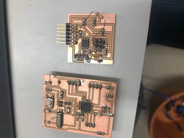
Satshakit Master Satshakit Slave
I relied heavily on this Master Reader/Slave Sender Arduino tutorial found on Sarah Coston’s site.
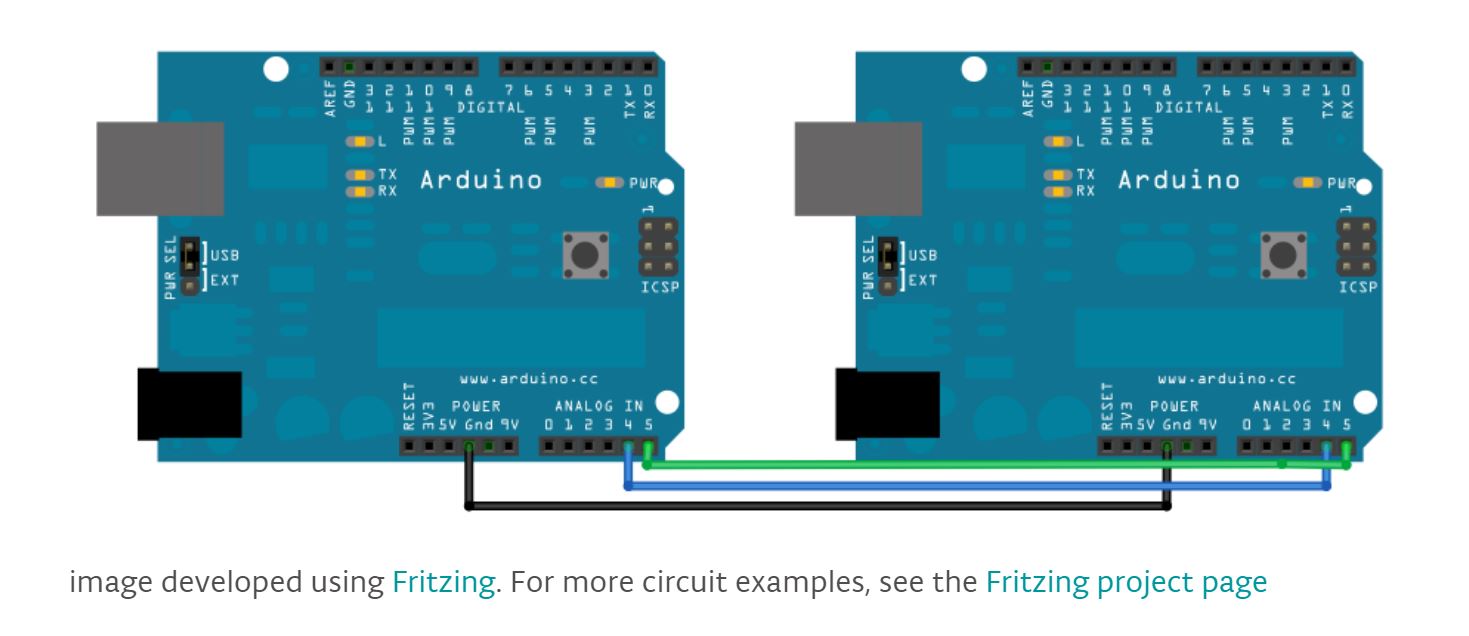
This example used I2C synchronous serial protocol to communicate between the two boards. Here is a good walkthrough of I2C protocol that I found on Ms. Fabian’s site.
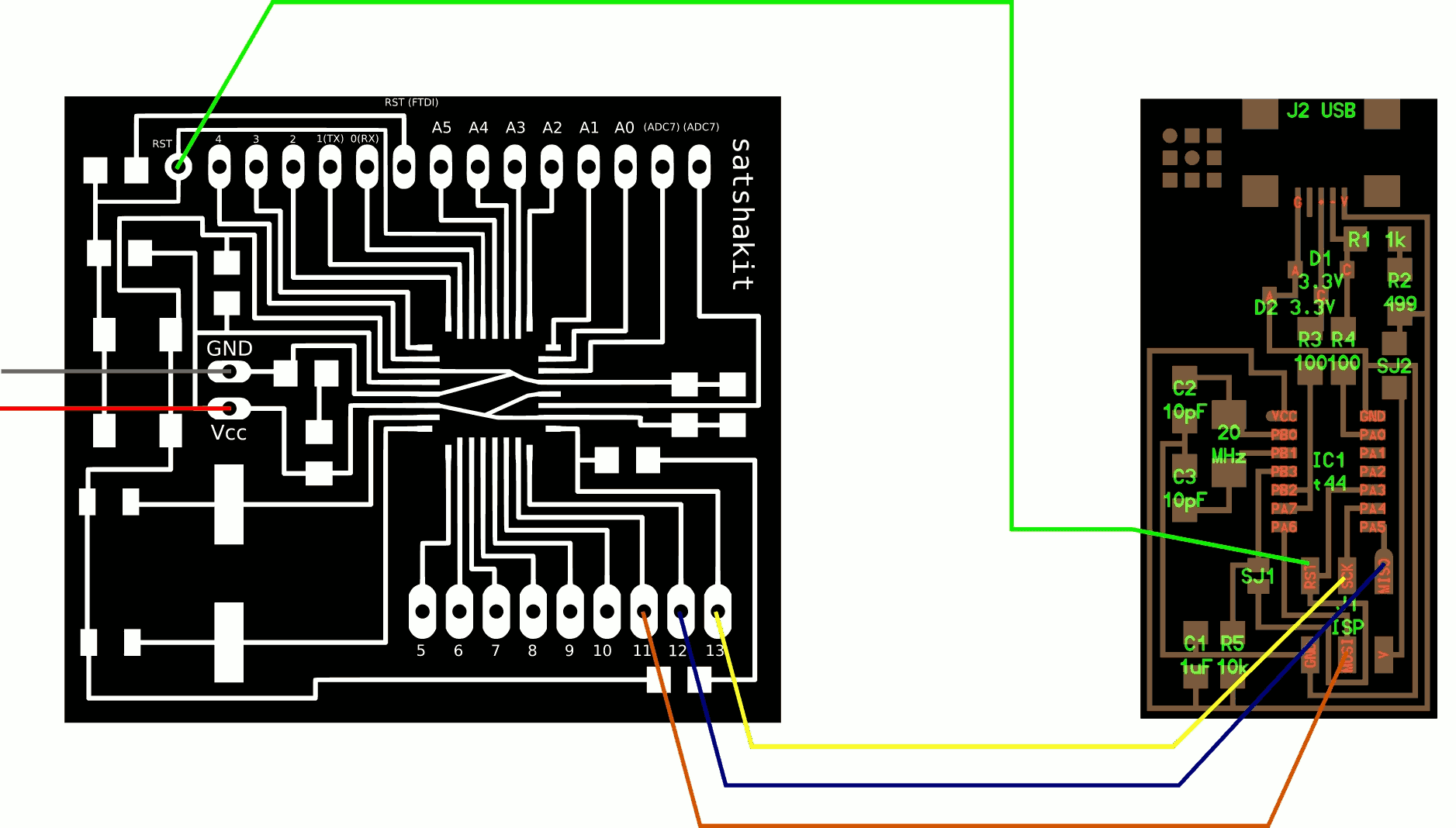
To transfer the connections depicted in the tutorial to the Satshakit, I referred to the Satshakit pinout.
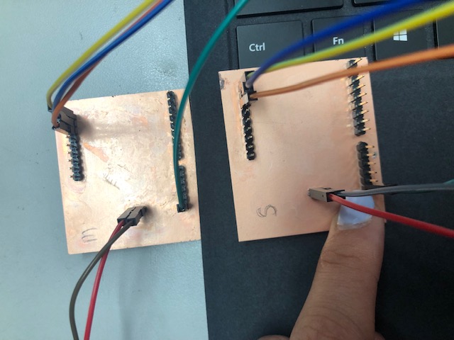
I also marked my two satshakit boards with pen.
Here is the Master Code:
// Wire Master Reader
// by Nicholas Zambetti <http://www.zambetti.com>

// Demonstrates use of the Wire library
// Reads data from an I2C/TWI slave device
// Refer to the "Wire Slave Sender" example for use with this

// Created 29 March 2006

// This example code is in the public domain.


#include <Wire.h>

void setup() {
 Wire.begin();        // join i2c bus (address optional for master)
 Serial.begin(9600);  // start serial for output
}

void loop() {
 Wire.requestFrom(8, 6);    // request 6 bytes from slave device #8

 while (Wire.available()) { // slave may send less than requested
   char c = Wire.read(); // receive a byte as character
   Serial.print(c);         // print the character
 }

 delay(500);
}
Here is the Slave Code:
// Wire Slave Sender
// by Nicholas Zambetti <http://www.zambetti.com>

// Demonstrates use of the Wire library
// Sends data as an I2C/TWI slave device
// Refer to the "Wire Master Reader" example for use with this

// Created 29 March 2006

// This example code is in the public domain.


#include <Wire.h>

void setup() {
 Wire.begin(8);                // join i2c bus with address #8
 Wire.onRequest(requestEvent); // register event
}

void loop() {
 delay(100);
}

// function that executes whenever data is requested by master
// this function is registered as an event, see setup()
void requestEvent() {
 Wire.write("hello "); // respond with message of 6 bytes
 // as expected by master
}
To better understand these two code files, I referred to the Arduino Wire library.
I started by coding the Master Board. This is the first error message I received when I tried to upload the code.
avrdude: Version 6.3-20171130
        Copyright (c) 2000-2005 Brian Dean, http://www.bdmicro.com/
        Copyright (c) 2007-2014 Joerg Wunsch

        System wide configuration file is "C:\Program Files\WindowsApps\ArduinoLLC.ArduinoIDE_1.8.21.0_x86__mdqgnx93n4wtt\hardware\tools\avr/etc/avrdude.conf"

        Using Port                    : usb
        Using Programmer              : usbtiny
avrdude: usbdev_open(): Found USBtinyISP, bus:device: bus-0:\\.\libusb0-0001--0x1781-0x0c9f
        AVR Part                      : ATmega328P
        Chip Erase delay              : 9000 us
        PAGEL                         : PD7
        BS2                           : PC2
        RESET disposition             : dedicated
        RETRY pulse                   : SCK
        serial program mode           : yes
        parallel program mode         : yes
        Timeout                       : 200
        StabDelay                     : 100
        CmdexeDelay                   : 25
        SyncLoops                     : 32
        ByteDelay                     : 0
        PollIndex                     : 3
        PollValue                     : 0x53
        Memory Detail                 :

                                 Block Poll               Page                       Polled
          Memory Type Mode Delay Size  Indx Paged  Size   Size #Pages MinW  MaxW   ReadBack
          ----------- ---- ----- ----- ---- ------ ------ ---- ------ ----- ----- ---------
          eeprom        65    20     4    0 no       1024    4      0  3600  3600 0xff 0xff
          flash         65     6   128    0 yes     32768  128    256  4500  4500 0xff 0xff
          lfuse          0     0     0    0 no          1    0      0  4500  4500 0x00 0x00
          hfuse          0     0     0    0 no          1    0      0  4500  4500 0x00 0x00
          efuse          0     0     0    0 no          1    0      0  4500  4500 0x00 0x00
          lock           0     0     0    0 no          1    0      0  4500  4500 0x00 0x00
          calibration    0     0     0    0 no          1    0      0     0     0 0x00 0x00
          signature      0     0     0    0 no          3    0      0     0     0 0x00 0x00

        Programmer Type : USBtiny
        Description     : USBtiny simple USB programmer, https://learn.adafruit.com/usbtinyisp
avrdude: programmer operation not supported

avrdude: Using SCK period of 10 usec
avrdude: AVR device initialized and ready to accept instructions

Reading | ################################################## | 100% 0.00s

avrdude: Device signature = 0x000000 (retrying)

Reading | ################################################## | 100% 0.00s

avrdude: Device signature = 0x000000 (retrying)

An error occurred while uploading the sketch
Reading | ################################################## | 100% 0.00s

avrdude: Device signature = 0x000000
avrdude: Yikes!  Invalid device signature.
        Double check connections and try again, or use -F to override
        this check.


avrdude done.  Thank you.
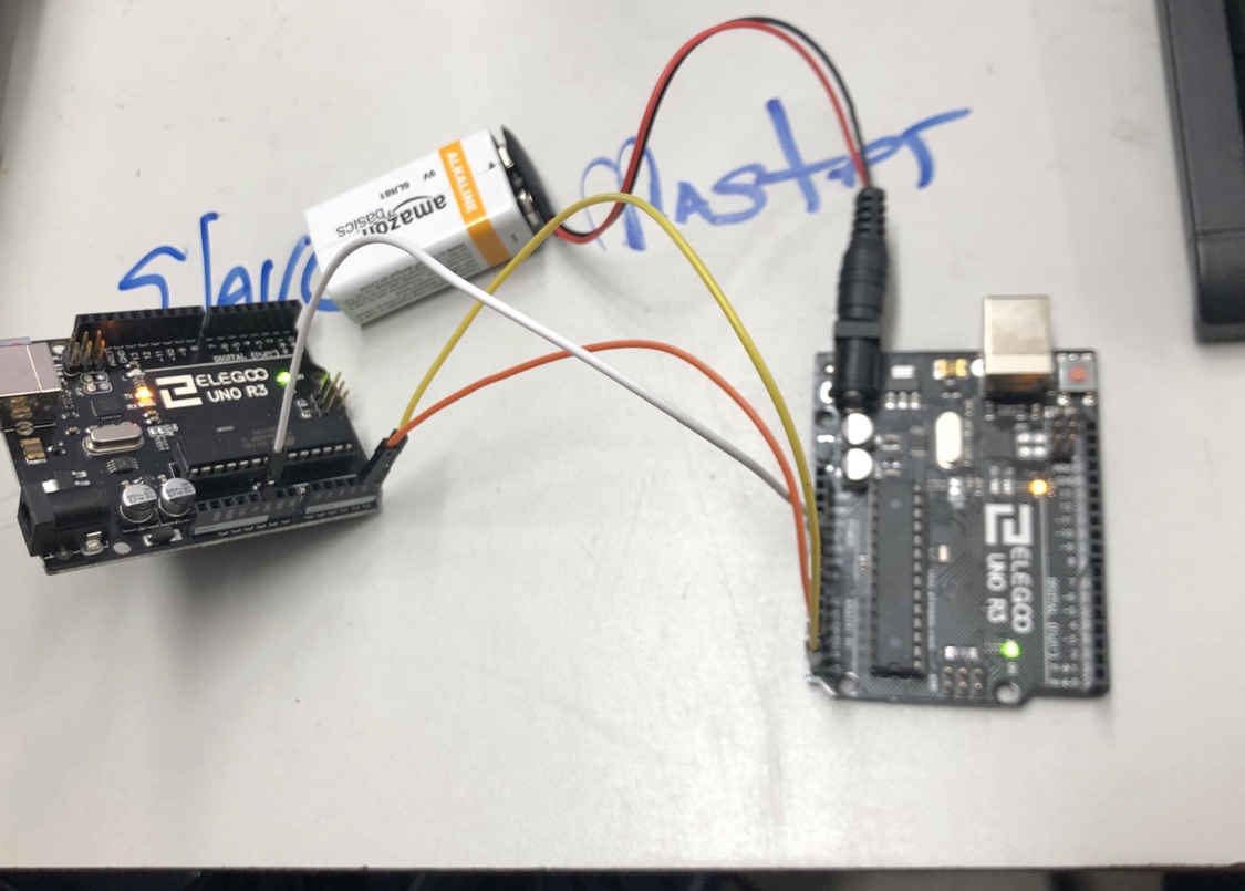
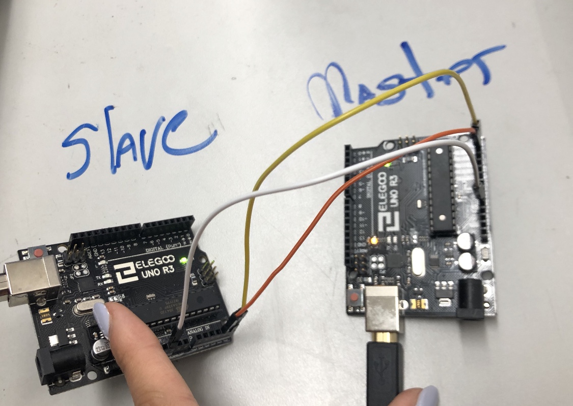
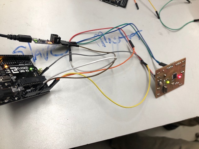
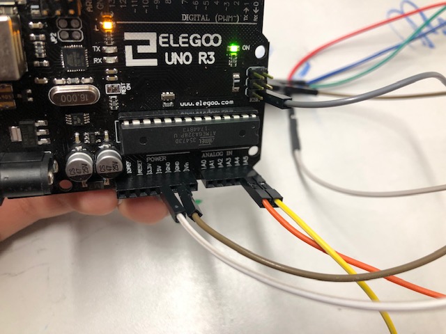
Arduino Master Arduino Slave
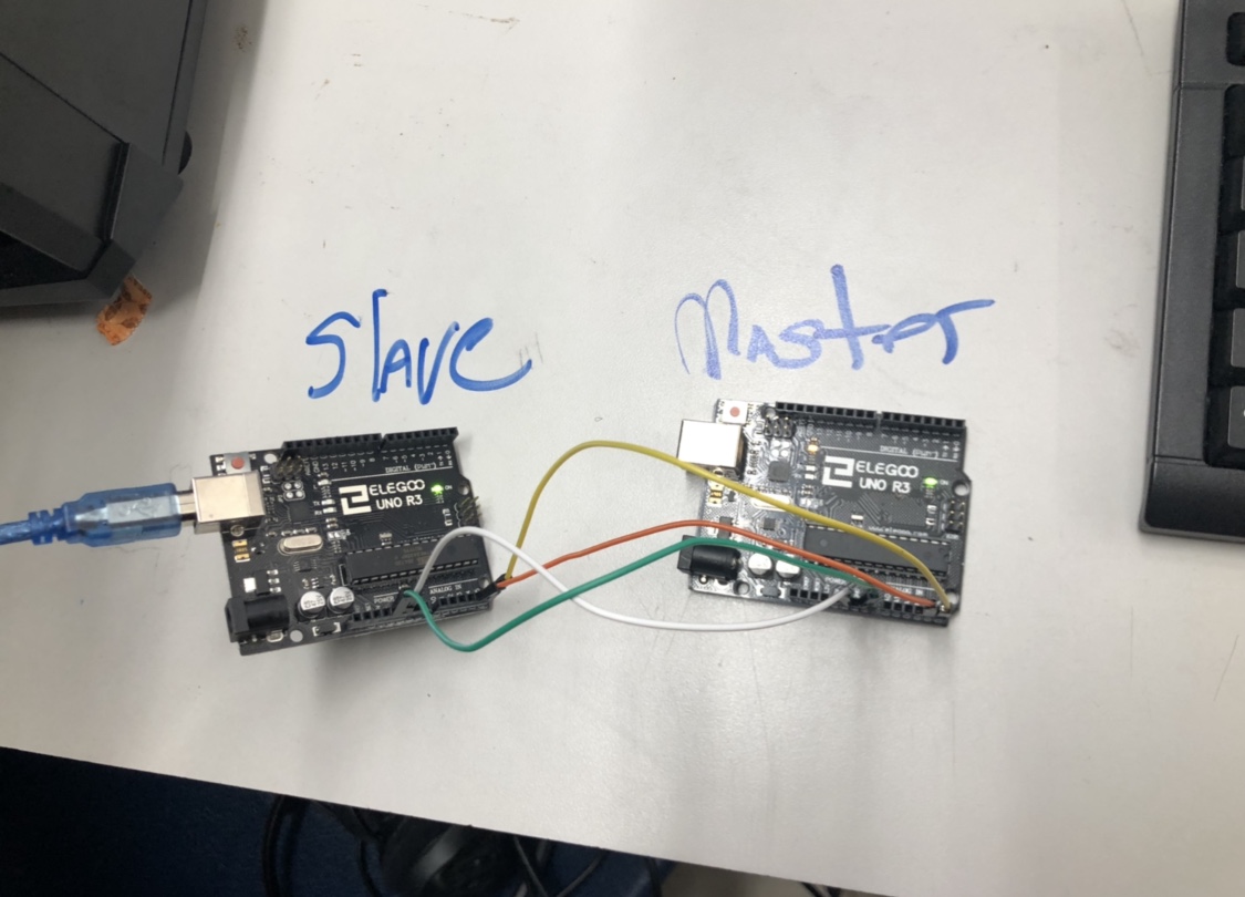
I was not exactly sure what was wrong with my connections, so I switched my satshakit boards out for Arduinos.
I started by programming my master board with the master code. I marked my master board with a piece of blue tape.
Then, I uploaded the slave code to the slave board.
Problems with Power Source
Initially, I had both boards being powered by the same computer. I also tried to only power the master through the computer.
After reading the tutorial again with Mr. Dubick, I figured out that I could power the slave board through the computer and then power the master board through the slave board. I decided to power the master board with a 9V battery. This did not work.
I tried to power the master board through the suggested 5V to VIN connection that the tutorial suggested. Even after I had powered the boards as the tutorial suggested, I was not able to get the boards to communicate.
I tried looking up some support documents/forums. I didn’t find anything that mirrored the problem that I was having, but I did find another tutorial called “Master Writer/Slave Receiver”. It uses the same I2C synchronous serial protocol and same connections.
Master Writer Slave Receiver
Here is the master code.
// Wire Master Writer
// by Nicholas Zambetti <http://www.zambetti.com>

// Demonstrates use of the Wire library
// Writes data to an I2C/TWI slave device
// Refer to the "Wire Slave Receiver" example for use with this

// Created 29 March 2006

// This example code is in the public domain.


#include <Wire.h>

void setup() {
 Wire.begin(); // join i2c bus (address optional for master)
}

byte x = 0;

void loop() {
 Wire.beginTransmission(8); // transmit to device #8
 Wire.write("x is ");        // sends five bytes
 Wire.write(x);              // sends one byte
 Wire.endTransmission();    // stop transmitting

 x++;
 delay(500);
}
This is the slave code.
// Wire Slave Receiver
// by Nicholas Zambetti <http://www.zambetti.com>

// Demonstrates use of the Wire library
// Receives data as an I2C/TWI slave device
// Refer to the "Wire Master Writer" example for use with this

// Created 29 March 2006

// This example code is in the public domain.


#include <Wire.h>

void setup() {
 Wire.begin(8);                // join i2c bus with address #8
 Wire.onReceive(receiveEvent); // register event
 Serial.begin(9600);           // start serial for output
}

void loop() {
 delay(100);
}

// function that executes whenever data is received from master
// this function is registered as an event, see setup()
void receiveEvent(int howMany) {
 while (1 < Wire.available()) { // loop through all but the last
   char c = Wire.read(); // receive byte as a character
   Serial.print(c);         // print the character
 }
 int x = Wire.read();    // receive byte as an integer
 Serial.println(x);         // print the integer
}
This did not work either… I did find this forum discussion that seemed similar to my problems. Unfortunately, their solution to the problem was to “Get a good night’s sleep, don’t modify anything and try again the next day” as “Time heals all”. I did not find this helpful.
Still, I decided to continue to experiment with the Master Writer/Slave Receiver code the next day.
The next day, I tried the experiment again. I unplugged the USB, closed my code files, and re-uploaded the code. It worked! I believe the problem with my experiment from yesterday was the USB connection.
With the help of Mr. Dubick, I tested different variables in my experiment from yesterday to figure out what had gone wrong so that moving forward with my Satshakit, I would be 100% prepared. We decided to try to switch out the 5V to VIN connection on the working boards for a 9V battery and then a power cable to another computer.
5V to VIN Connection:

9V Battery:
Power cable:
Here is a video of my boards working with both the 5V to VIN connections and the 9V battery connection.
Satshakit Master Satshakit Slave
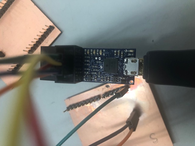
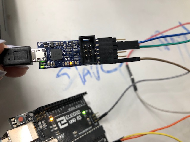
Pololu Programmer
Once my Arduino boards were working, I moved back to my satshakits with the help of Dr. Harris. I hooked up each board individually to his Pololu programmer. This programmer can program and power boards!
Here is the Pololu programmer pinout Pololu programmer Arduino settings
To hook up the Satshakit board to this programmer, I again referred to the Satshakit programmer pinout.
.
I attempted to program both both boards, but when i connected them to the power and ground of the programmer, the programmer would restart. This could be seen from the lights on the programmer turning off when the boards were connected.
Dr. Harris explained to me that there was a short somewhere in my board. Using a multimeter, exacto knife, and microscope, I examined my to boards. I hoped to get one working so that I could test it with one of the programmed Arduinos that I worked on earlier that day.
Resurrected Satshakit and ATtiny45 Board
After an hour of resoldering and scraping, I could not fix the short. Dr. Harris recommended that I switch out the Satshakits for one of my boards from my board bag. (This bag is filled with half soldered/failed boards from earlier weeks.)
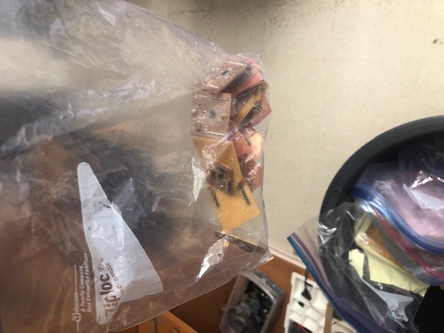
I decided to try to resurrect two boards: my edited satshakit from input week (week 11) and my attiny45 board from output week (week 12).
My first attempt with these new boards was with my input satshakit and an Arduino. I kept the Arduino master board and tried to network it to the slave input satshakit. It worked!
Here is a video of my Arduino Master Edited Satshakit Slave.
Here are a few pictures of the connections.
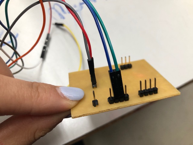
After I got one board working, I tried again to fix one of the two satshakits meant for this week. I hoped that if I fixed one short, I could use that board with my resurrected satshakit board for networking. I still could not get them to work. After inspecting my board file, I found that the RX/TX pins were still on the board. I believe we may have been attaching the wires to the wrong pins.
I realized that I do not have a programmer because my last one broke a few weeks ago. I have decided to order a pololu programmer! Yay!
ATtiny45 Master Satshakit Slave
Tiny.m Library
Instead, I decided to try to get my attiny45 board working as a master. To do this, Dr. Harris helped me find the Tiny.m (tiny master) library in Arduino IDE. He also helped me translate my code that used the Wire.h library into this new library. Mark Ng’s site helped us check our translation as he used the same setup.
#include <TinyWireM.h>
#define device (1)
void setup() {
TinyWireM.begin();
}
void loop() {
TinyWireM.beginTransmission(device);
TinyWireM.send(1);
TinyWireM.endTransmission();
delay(2000);
TinyWireM.beginTransmission(device);
TinyWireM.send(0);
TinyWireM.endTransmission();
delay(2000);
}
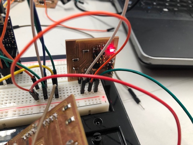
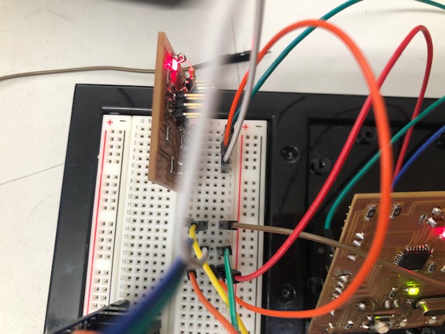
After I had programmed both boards, I hooked up my satshakit slave board to my attiny45 master board.
Here is a picture of my setup.
This did not work. :(!!!!
Satshakit Master ATtiny45 Slave
I decided to switch my master and slave boards. To do this, I had to add two pull up resistors to the attiny45 board (slave).
Here is are two good references that Dr. Harris showed me to explain the concept of pull-up resistors.
Here is a picture of my soldered on pull-up resistor.
Here is the code for the master satshakit. (Both of these codes were found on Mark’s site.)
#include <Wire.h>
void setup()
{
Wire.begin(); // join i2c bus (address optional for master)
Serial.begin(9600); // start serial for output
}

void loop()
{
Wire.requestFrom(4, 1); // request 1 byte from slave device address 4
while(Wire.available()) // slave may send less than requested
{
int i = Wire.read(); // receive a byte as character
Serial.println(i); // print the character
}

delay(500);
}
Tiny.s Library
Here is the code for the slave attiny45.
This code references the Tiny.s library. While the Tiny.m library was already in the Arduino IDE program, the Tiny.s library was not.
Here is the link to the Tiny.s library.
// Code for the ATtiny85
#define I2C_SLAVE_ADDRESS 0x4 // Address of the slave
#include <TinyWireS.h >
int i=0;
void setup()
{
TinyWireS.begin(I2C_SLAVE_ADDRESS); // join i2c network
//TinyWireS.onReceive(receiveEvent); // not using this
TinyWireS.onRequest(requestEvent);
// Turn on LED when program starts
pinMode(1, OUTPUT);
digitalWrite(1, HIGH);
}
void loop()
{
// This needs to be here
TinyWireS_stop_check();
} // Gets called when the ATtiny receives an i2c request
void requestEvent()
{ TinyWireS.send(i);
i++;
}
Clock Speed
I uploaded both to the boards, but it didn’t work. After reading through the tutorial again, Dr. Harris and I found a small paragraph at the end of the documentation that specified the speeds of the internal clocks of both chips.
Here is the passage.
“There are not many examples of using Attiny as master and slave. I find this topic a liitle difficult to understand. The Attiny( both master and slave) if set at 1Mhz, the communication becomes very slow. It is only when I set the slave to faster speed(at 8Mhz ) and the master at 1 Mhz then everything began to work. I would like to explore further on this like driving an I2C LCD , adding different devices like raspberry pi to the bus later.”
Even after making these changes, my boards would still not work. I tried to isolate both boards by using them in conjunction with my pre-programmed arduinos. After doing this, I found that my attiny45 board was working while my arduino board was not.
Here is a video of my attiny45 working with an Arduino master.
I was still not sure why my boards were not working. To better understand the new code and setup, Dr. Harris showed me how to program two Arduinos with the code from Mark’s site.
Here is the video of the Arduino Master Arduino slave.
A few days after my failed experiments, Dr. Harris sent me an email with a discovery! We had been connecting the RX/TX wires to the wrong pins on the satshakit. Since I had edited the satshakit to fit my requirements for the input week, I would need to use the software serial library. After examining my board file, I found that the RX/TX pins were on the board but in the middle. (I believe that we were connecting the RX/TX wires to the wrong pins). Sadly I am not able to test my hypothesis because all of my programmers have broken. I have decided to order this Pololu programmer!
Fast forward to the next week. I decided to make two new satshakits. I soldered them with a new type of pin header which curved outward. While these pin headers were easier to hook up to the programmer, they were too thin to pop into the male to male wires. Dr. Harris explained that I could either create custom pin adaptors for the thinner pins or re-solder thicker pins.
Here is a picture of the thinner pins and the pin adaptors.
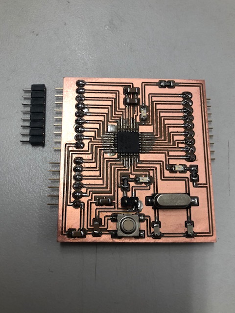
We got out the supplies to create the custom wire adaptors, but then realized that the way I had soldered the pin headers onto the board could potentially cause a short. (I did not solder the plastic pieces touching the back of the board.)
While meeting with Dr. Harris the second time, he taught me how to use a printed message to indicate whether the boards were sending and receiving messages. We printed the message, “Hi”. Once we did this,it was easier to figure out if a board was working or not.
Here is a video showing the “Hi” indicator working.
Today is Tuesday. I think I figured out my problem. For the past couple experiments, I have been using my board design from week 11. The other boards that I have used have either been shorted or ATtiny45s. Today, I remembered that my board from week 11 was made with my force sensor in mind. Because of that, I added a 10k resistor on my board where the board was being programmed and connected to the other boards! I believe this forgotten resistor could be the root of all my problems for the last few weeks.
Moving forward, I plan to resolder another satshakit that does not have the 10k resistors incorporated. Hopefully, this will fix my problems… fingers crossed!
After referencing a pinout diagram for the board with Dr. Harris, we found out that the resistors would not have an effect on the networking.
ATtiny 45 Master ATtiny 45 Slave
With Dr. Harris, I moved onto hacking a failed ATtiny45 from my bag board to become a master board.
I started by fixing a 1k pull resistors on my slave board.
Then, Dr. Harris helped me program a new board as a master. It programmed!
Then we tested the master and slave ATtiny 45 boards. We powered them through the pololo programmer. The slave was set to 8 MHz and the master was set to 1 MHz. The address was set to 1. It seemed to work because the light turned on, but it didn’t look like Mark’s example video.
We decided to reprogram both boards to check their clock speeds. They seemed to be programmed correctly. Next, we checked the connection wires. They were not correct! We switched them around and the LED turned on! It did not turn off though…
After looking back at some old code, Dr. Harris hypothesized that we have been using a strange slave example code. We looked at the code line by line and found that the slave was working in reverse. It was acting like the master!
We switched back to the original Satshakit Master and ATtiny45 experiment to see if our code for the slave was the problem.
It’s still not working.
Oscilloscope Comparisons
Dr. Harris helped me compare the different oscilloscope readings for my boards and the Arduino boards.
Here is the reading from the working oscilloscope reading. It is at 255 (which is the number displayed on the serial monitor).
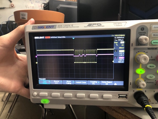
He hooked up the other board and we compared. For some reason, the board was not reaching the right voltage level. The yellow line is nowhere near the purple line.
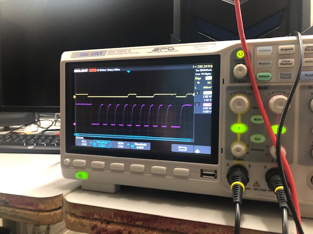
Yellow: clock
Purple: data
Serial Communication with Addresses
Today, I decided to switch to a simpler method of communication that used Serial communication and addresses. I decided to do this after talking to Dr. Harris about the problems from the last few weeks. Dr. Harris actually took my board back to his workplace to figure out if there was a bigger problem at hand. After studying the board for a week, he was unable to locate the problem and recommended that I try something new because I would be leaving for Germany in one week.
He recommended that I use a Satshakit as as master with two Attiny45 board slaves for the assignment this week. I would send a message to the Tiny 45s from the Satshakit. The message would contain the address for one of the two Tiny 45 boards. If the 45 board recognized the address, it would blink an LED!
For this communication, Dr. Harris showed med how to use the software serial code to create a sort of XOR logic gate that would toggle the LED. He also explained that I would need to make sure the slave board matched its address to the address that it was supposed to be sent to. I set the RX connection to be pin 2.
The first thing I did was desolder the pull up resistor from pin two. For this new method of communication, I would use this pin for communication.
Here is a video that shows the toggling. This board is addressed to A. When we typed “A” into the serial monitor, the LED turned on!
Here is a video of that!
Next, we added another one of my boards to the system.
When we tried to program my other two boards, we found that there was a short somewhere on the boards. We concluded this because the LED on the boards was constantly on.
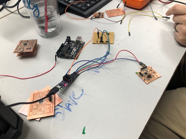
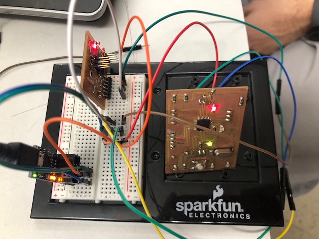
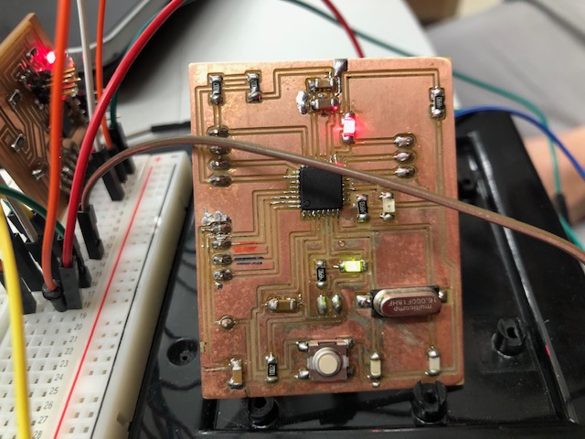
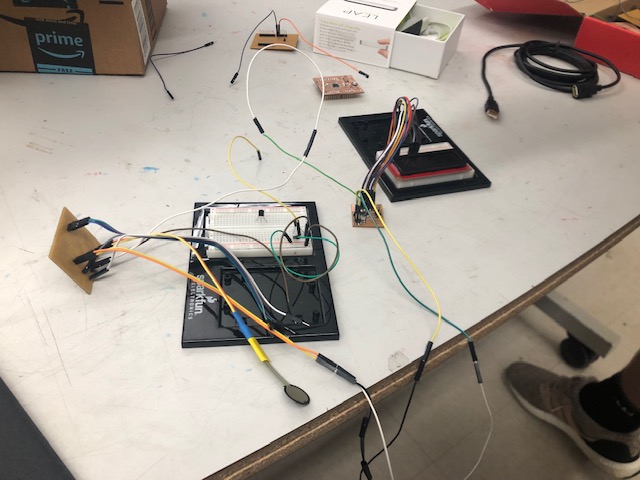
Dr. Harris tried the program out on his board to check it and it worked. Here are the two wired nodes (one of which is Dr. Harris’s board).
We replaced that Attiny45 board with my Satshakit. It worked!
Here are my two wired nodes communicating! Yay!!!!! :)
Here is the code for Address A. This is for the Tiny45 board.
#include <SoftwareSerial.h>
byte myAddress = 'A';

SoftwareSerial mySerial(2, 1); // RX, TX

void setup()
{
pinMode(3, OUTPUT);

 // set the data rate for the SoftwareSerial port
 mySerial.begin(4800);

}//end setup

void loop() // run over and over
{
 if (mySerial.available()){
   byte inputAddress = mySerial.read();
   if (inputAddress == myAddress){
  //toggle LED on pin3
 //Reference for Xor method: http://www.bristolwatch.com/arduino2/eor.htm
 byte temp = digitalRead(3) ^ 1;
 digitalWrite(3, temp);


   }//end if my address
 }//end if serial available
}//end loop
Here is the code for Address B. This is for the Satshakit.
byte myAddress = 'B';

void setup() {
 //Initialize serial and wait for port to open:
 Serial.begin(4800);
  pinMode(13, OUTPUT);

}

// first visible ASCIIcharacter '!' is number 33:
int thisByte = 33;
// you can also write ASCII characters in single quotes.
// for example, '!' is the same as 33, so you could also use this:
// int thisByte = '!';

void loop() {
   if (Serial.available()){
   byte inputAddress = Serial.read();
   if (inputAddress == myAddress){
  //toggle LED on pin3
 //Reference for Xor method: http://www.bristolwatch.com/arduino2/eor.htm
 byte temp = digitalRead(13) ^ 1;
 digitalWrite(13, temp);


   }//end if my address
 }//end if serial available
}
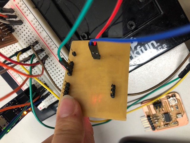
These are the connections between the two boards. The blue board is the Pololu programmer.
Group Assignment: Send a message between two projects
For our group project this week, we worked to network my input satshakit board to an LCD screen.
The Satshakit was used as a sending device. It was connected to a Force Sensitive Resistor. Kai developed this setup during week 11 with a temperature sensor and his variation of the Satshakit.
Here is a video of the force sensitive resistor receiving data. It is using the Serial monitor on the Arduino IDE.
A LCD screen was used to receive the data/signals (the temperature readings) from the temperature sensor.
Here is a video of the LCD screen connected to Kai’s breakout board.
To get these two device to communicate, the Serial TX on the Satshakit+Force Sensitive Resistor was connected to the Serial RX on the LCD screen board.
Thank you Kai and Maxine for developing and troubleshooting the Serial Monitor part of this week’s group assignment. They laid the vast majority of groundwork needed to finish this project.
Here is a video which demonstrate the functioning of the networked projects.
Files
Here are my test code files from this week. Download Files