7. Electronics design
This week, I started designing electronic circuits. I primarily used Eagle for the Hello World board by Professor Gershenfeld.
TinkerCircuit
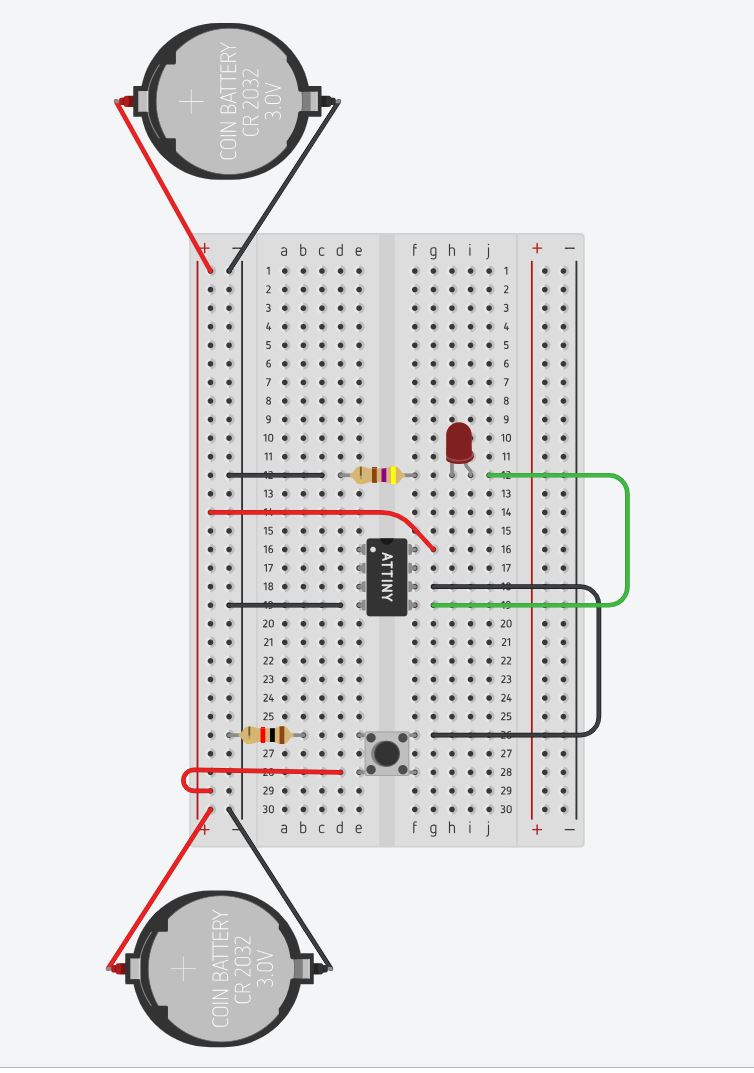
Before working in Eagle, I played around with the Tiny45 in TinkerCircuit. TinkerCircuit is a simplistic circuit designer marketed toward children. This helped me to comprehend the connections and arrangment of the different components. (TinkerCircuit actually lets you export your design as a .brd file which is what Autodesk Eagle uses!)
Still, because of the component limitations, I could only experiment with a Tiny 45 not a Tiny 44. The Tiny 45 has fewer ports which meant it would not be a perfect replication of the final Hello World board.
Here is the digital bread board I created.

I simulated the design and found that the Tiny 45 was being overloaded.

I switched out the 9V battery for two 3V batteries which seemed to solve the problem.
Electrical Theory
When designing the circuit board, I learned about a few equations that would determine component values. Here are my notes!
Ohm’s Law To solve for a variable in Ohm’s law, I covered the variable in the triangle and perform the relative operation!

This is a more in depth pie chart of Ohm’s law and a few more equations.

Kirchoff’s 3 Laws: - Conservation of Charge (Kirchhoff’s First Law) - “Total current or charge entering a junction or node is exactly equal to the charge leaving the node as it has no other place to go except to leave, as no charge is lost within the node”
Node - a connection or junction of two or more current carrying paths or
- Conservation of Energy (Kirchhoff’s Second Law) - “In any closed loop network, the total voltage around the loop is equal to the sum of all the voltage drops within the same loop”
Circuit – a circuit is a closed loop conducting path in which an electrical current flows Path – a single line of connecting elements or sources Branch – a branch is a single or group of components such as resistors or a source which are connected between two nodes Loop – a loop is a simple closed path in a circuit in which no circuit element or node is encountered more than once Mesh – a mesh is a single open loop that does not have a closed path. There are no components inside a mesh
Eagle
Autodesk Eagle is another, more complex circuit designing software. Similar to TinkerCircuit, the program allows you to drag in components and draw paths. It also shows you the possible design complications that could take place when milling.
Before starteing on my Hello World board, I uploaded the Fab Library into Eagle.
I found the library by searching fab.lbr.


To remake the Hello World Board, I began by making a project and a schematic. (The green dot will show you your active project.)

I put in an 8.5 x 11 inch frame in case I wanted to print my design.

Once I framed my schematic, I added my components. (I referred to the Fab Academy photos and Mr. Rudolf’s site to get a general idea of their names so I could search them in the Fab library
Components:
-
button
-
switch
-
resistor
-
capacitor
-
crystal/resonator
-
diode (LED)
-
microcontroller (Tiny 44)

Once my parts were laid out, I connected them with the net tool. I found that connections were shown as nodes (which looked like dots) (I also decided to label a few significant wires for example the ground).

Later, I decided to label all the connections, because I liked the way it looked.
I also added values to the resistors and the capacitor.

Once I was happy with my connections, I generated a board from my schematic.

In this viewer, you can choose to autoroute your paths or route them by hand. I decided to route the board by hand for fun! (It was in no way fun.) I set my paths’ widths to 12.

When routing, it is important to avoid other components or paths. You also have to leave enough space for the milling maching to be able to cut. To ensure your paths are physically possible, you can utilize two checking methods: 1) Open the design in Bantam and 2) Use the DRC or design rule check.
I found that my board was not physically possible because my traces were too close together. To remedy this, I used a 0 ohm resitor as a jumper.

Before exporting to the milling machine, I changed the visibility of the layers so that only the top layer would be seen.

Milling
I uploaded my board design from Eagle directly into Bantam tools.

Here is what my traces looked like:

This is my outline:

While milling my third board, the milling machine band broke which caused the bit to stop spinning. This then caused the bit to break in my half-milled board.

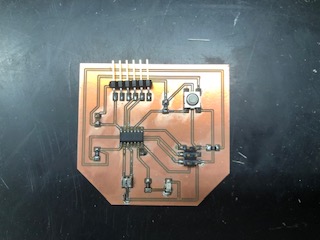
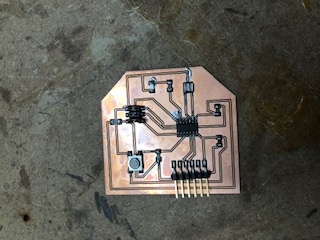
This is one of my final milled boards:

Soldering
I started by collecting the components mentioned above.

After I was done soldering, I cleaned my board with acetone.
Before:
After:
After soldering a few boards, I found that my pin header would often disconnect from my board resulting in a torn trace.

Dr. Harris reccommended that I connect the pin header using male to female wires instead of connecting it directly. This significantly reduced the stress on the component and solved the problem.
Programming
To test my Hello World board, I tried to run the Hello World Echo code provided by Professor Gershenfeld in Arduino IDE.
I made one change to the code after discussing the programming process with my classmate, Will. He had figured out that you had to add one line of code to the setup. Thanks, Will!
# define F_CPU 20000000
Here is the code:
//
//
// hello.ftdi.44.echo.c
//
// 115200 baud FTDI character echo, with flash string
//
// set lfuse to 0x5E for 20 MHz xtal
//
// Neil Gershenfeld
// 12/8/10
//
// (c) Massachusetts Institute of Technology 2010
// This work may be reproduced, modified, distributed,
// performed, and displayed for any purpose. Copyright is
// retained and must be preserved. The work is provided
// as is; no warranty is provided, and users accept all
// liability.
//

# define F_CPU 20000000

#include <avr/io.h>
#include <util/delay.h>
#include <avr/pgmspace.h>

#define output(directions,pin) (directions |= pin) // set port direction for output
#define set(port,pin) (port |= pin) // set port pin
#define clear(port,pin) (port &= (~pin)) // clear port pin
#define pin_test(pins,pin) (pins & pin) // test for port pin
#define bit_test(byte,bit) (byte & (1 << bit)) // test for bit set
#define bit_delay_time 8.5 // bit delay for 115200 with overhead
#define bit_delay() _delay_us(bit_delay_time) // RS232 bit delay
#define half_bit_delay() _delay_us(bit_delay_time/2) // RS232 half bit delay
#define char_delay() _delay_ms(10) // char delay

#define serial_port PORTA
#define serial_direction DDRA
#define serial_pins PINA
#define serial_pin_in (1 << PA0)
#define serial_pin_out (1 << PA1)

#define max_buffer 25

void get_char(volatile unsigned char *pins, unsigned char pin, char *rxbyte) {
   //
   // read character into rxbyte on pins pin
   //    assumes line driver (inverts bits)
   //
   *rxbyte = 0;
   while (pin_test(*pins,pin))
      //
      // wait for start bit
      //
      ;
   //
   // delay to middle of first data bit
   //
   half_bit_delay();
   bit_delay();
   //
   // unrolled loop to read data bits
   //
   if pin_test(*pins,pin)
      *rxbyte |= (1 << 0);
   else
      *rxbyte |= (0 << 0);
   bit_delay();
   if pin_test(*pins,pin)
      *rxbyte |= (1 << 1);
   else
      *rxbyte |= (0 << 1);
   bit_delay();
   if pin_test(*pins,pin)
      *rxbyte |= (1 << 2);
   else
      *rxbyte |= (0 << 2);
   bit_delay();
   if pin_test(*pins,pin)
      *rxbyte |= (1 << 3);
   else
      *rxbyte |= (0 << 3);
   bit_delay();
   if pin_test(*pins,pin)
      *rxbyte |= (1 << 4);
   else
      *rxbyte |= (0 << 4);
   bit_delay();
   if pin_test(*pins,pin)
      *rxbyte |= (1 << 5);
   else
      *rxbyte |= (0 << 5);
   bit_delay();
   if pin_test(*pins,pin)
      *rxbyte |= (1 << 6);
   else
      *rxbyte |= (0 << 6);
   bit_delay();
   if pin_test(*pins,pin)
      *rxbyte |= (1 << 7);
   else
      *rxbyte |= (0 << 7);
   //
   // wait for stop bit
   //
   bit_delay();
   half_bit_delay();
   }

void put_char(volatile unsigned char *port, unsigned char pin, char txchar) {
   //
   // send character in txchar on port pin
   //    assumes line driver (inverts bits)
   //
   // start bit
   //
   clear(*port,pin);
   bit_delay();
   //
   // unrolled loop to write data bits
   //
   if bit_test(txchar,0)
      set(*port,pin);
   else
      clear(*port,pin);
   bit_delay();
   if bit_test(txchar,1)
      set(*port,pin);
   else
      clear(*port,pin);
   bit_delay();
   if bit_test(txchar,2)
      set(*port,pin);
   else
      clear(*port,pin);
   bit_delay();
   if bit_test(txchar,3)
      set(*port,pin);
   else
      clear(*port,pin);
   bit_delay();
   if bit_test(txchar,4)
      set(*port,pin);
   else
      clear(*port,pin);
   bit_delay();
   if bit_test(txchar,5)
      set(*port,pin);
   else
      clear(*port,pin);
   bit_delay();
   if bit_test(txchar,6)
      set(*port,pin);
   else
      clear(*port,pin);
   bit_delay();
   if bit_test(txchar,7)
      set(*port,pin);
   else
      clear(*port,pin);
   bit_delay();
   //
   // stop bit
   //
   set(*port,pin);
   bit_delay();
   //
   // char delay
   //
   bit_delay();
   }

void put_string(volatile unsigned char *port, unsigned char pin, char *str) {
   //
   // print a null-terminated string
   //
   static int index;
   index = 0;
   do {
      put_char(port, pin, str[index]);
      ++index;
      } while (str[index] != 0);
   }

int main(void) {
   //
   // main
   //
   static char chr;
   static char buffer[max_buffer] = {0};
   static int index;
   //
   // set clock divider to /1
   //
   CLKPR = (1 << CLKPCE);
   CLKPR = (0 << CLKPS3) | (0 << CLKPS2) | (0 << CLKPS1) | (0 << CLKPS0);
   //
   // initialize output pins
   //
   set(serial_port, serial_pin_out);
   output(serial_direction, serial_pin_out);
   //
   // main loop
   //
   index = 0;
   while (1) {
      get_char(&serial_pins, serial_pin_in, &chr);
      put_string(&serial_port, serial_pin_out, "hello.ftdi.44.echo.c: you typed \"");
      buffer[index++] = chr;
      if (index == (max_buffer-1))
         index = 0;
      put_string(&serial_port, serial_pin_out, buffer);
      put_char(&serial_port, serial_pin_out, '\"');
      put_char(&serial_port, serial_pin_out, 10); // new line
      }
   }
Once I had my code in an Arduino document, I downloaded and set up the 44 board settings.
To download the 44 board, I pasted this link into the board manager preferences.

Here is the link for the ATtiny 44 board

Here are my settings:

Here are some problems I faced when attempting to program my board.
- Port: After sucessfully programming my board, I tried to acess the serial moniter to send some messages, but I would get this error message that the port was busy.

This is an image of some code in Powershell (that Mr. Rudolf helped me set up) which helped to confirm the problem I was having in Arduino.

I found out that I had to remove the programmer and power the board from the computer.
- Device Signature: I recieved this error message mulitple times, but I figured out it had to do with the connection from the programmer to the board. To fix my connections, I refered to my board’s schematic and the schematic of the programmer to align the pinheads properly.


Here is a fun picture of some C code in Arduino that Mr. Rudolf taught us.

Group Assignment: Use the test equipment in your lab to observe the operation of a microcontroller circuit board
To complete this week’s assignment, we used the SDS1000X-E Series Digital Oscilloscope. I researched oscilloscope by watching this video and reading the oscilloscope manuel/quickstart guide. I used this oscilloscope one year ago to for a science competition. We only used it to find the voltage values required for our scaling equations, but I never truly dove into the specificities and details of the machine.
An oscilloscope helps debug circuits, shows electronic signals, and measures amplitude, frequency, transient signals that multimeters can’t catch.
Modern oscilloscopes take measurements using an analog to digital converter to sample signal and draw waveforms on screen.
Quickstart Setup
To set up quickstart, I followed these steps:
-
Adjust legs to tilt scanner
-
Connect to AC Power supply
-
Connect the probe to the BNC connector and circuit
-
Ground terminal to ground on circuit
-
Press default button to reset the setup
-
Use probe to connect the CH1 Input Terminal and Compensation Signal Output Terminal on the front panel
-
Press auto setup button
-
Look at the waveforms!
General Oscilloscope Setup
This is a video of my classmate, Will, walking through the process discussed in the Sparkfun Youtube video above.
Here is a photo of our probe connections:

BLINK Program
This is a video showing the waveforms of a standard Arduino BLINK program.
Here is the code that I got from the basic arduino programs:

Here are our probe connections for this test: (We connected it to groud and pin 13)

From the video, you can see a visual of the high and low commands used when coding.

DIY Oscilloscope
At the end of the video, we analyzed the BLINK code with a handheald, DIY oscilloscope that I made in my electrical engineering class

Files
Here are my STL files: Download Files