FINAL PROJECT
Index
- My Final Project Introduction
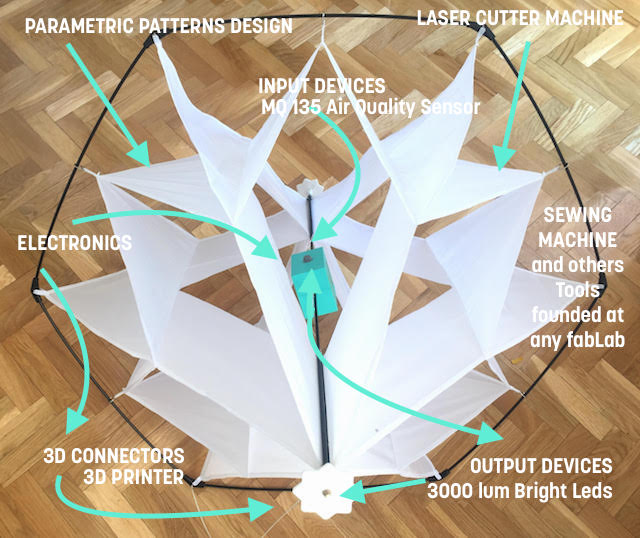
- Design 2D : The Parametric Kite Patterns & Laser Testers.
- Design 3D : The Kite : Madrid´s version for flight with 10 to 20 km/h.
- Design 3D : Mechannisms. Caps and Connectors.
- Design 3D : The Box for Electronics.
- Technologies Involves I : LASER CUTTER MACHINE PROCESSES
- Technologies Involves II : 3D PRINTERS PROCESSES
- Technologies Involves III : MILLER MACHINE PROCESSES
- Technologies Involves IV : SEWING MACHINE PROCESSES
- Electronics : Design and Fabrication
- The Atmel 168P Datasheet : What i learned and Howe it Helped to me?
- Learning about Gas Sensors. Callibration.
- EPPROM Programs for store and read sensor data.
- The Budget : An Approximated BOM
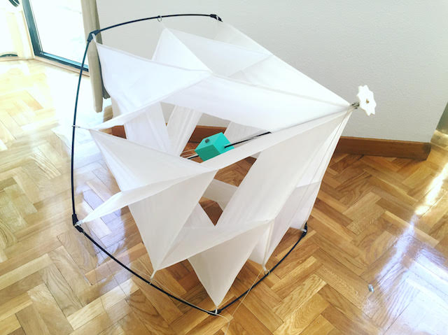
FAITO V.O1 : A FABABLE KITE FOR LEARN HOW TO RESPECT THE ENVIROMENT
Faito v.01 is a prototype develope during my Academy for learn How to fabricated Kites with the learns practice each week focussing on how to adapt the techniques and tools to kids.
Faito v.01 was designed as a part of research about Academy Tools suggested with the idea to use the more open Sources as possible an apply to my workshops when i finish.
Faito v.01 have the measures and weights ideal for have flights with Madrid´s wind forces so this was the idea for have something at the Final project presenattion but i designed inside "My Own Academy Spiral Nights" a second one with his parts for fly in the place i thought for first time, close to the Atlantic Sea.
Faito v.01 LEARN ME A LOT because i didn´t have experience at the design, fabrication or technologies used during the processes so EVERY MISTAKE was a lesson, every advance was a challenge, every processes opened other processes. I learned that now i have a Project for teh rest of my life if i want and I want
Faito v.01 should to have more sensors, should to be more complicated but it need as symply as possible for get the first interest of people who should to use it.
Faito v.01 is now a prototype which learned me how will to make the seconbd version, how not to make the same mistakes and probably have other news...
Faito v.01 have a mini-partner actually but still looking for more people or companies interested because the process learned to me how much will be your costs, Now I know the kite market and to what extent is it profitable to manufacture a kite in a fablab.
Faito v.01 as Neil´s mentioned at presentation is good for the class but both think that the second model can to have more input sensors studied during the Diploma i can´t to wait but i´m realistic Faito should to have more partners.
2D Y 3D DESIGN
The 2D design process started soon although a little blind since i had not yet advanced with my aerodynamic studies, on weight and trend in relation to other previous references which you can see at my research and conclusions sections in my :
Looking about other similar possible projects with my instructor, some mentioned in my Intellectual, Property and Income´s assignment page : WEEK 18 about WHAT OTHERS DID? , we found that my design is currently commercialized so that being a design that existed it was necessary to demonstrate what is different in my kite in terms of design and what am i trying to improve with my process.
Here is a vídeo founded on on internet where you can see how are the commercial designs :
or here, a guy who make beatiful snowflakes kite :
MY KITE Vs COMMERCIALS
Clearly i adore the faceted design, my intention when i ´m performing an equal is to demonstrate how easy is fabricate one by the tools and machines founded at the fablab and with wich processes should be better for fabricate a similar model as cheap as possible.
As I mentioned in my page FINAL PROJECT PROPOSAL : at WEEK 01
My initial idea was to design a kite that can to be designed easyly with the tools studied during my fabAcademy but always looking towards a practical future. For that reason my design processes follow the use different tools, commercials and open sources. For example, my prototype and after several attempts, was designed with Fusion 360º for the Kite´s patterns and laser testers designs, using the parametric functions of the program. So this will allow to everyone who wants modify the kite measurements in order to adapt the design to the new size needs.
My design add this extra, i didn´t found a patterns (or any patterns about the design) with the same properties before now the design is free and opensource.
The main reason about why my project is different is his final purpose, a tool for learn. The kite is not just for have fun when you fly it, you can to learn something about the environment.
The 2D design process had several attempts that you can know more in my final roject process page at 2D design and 3D sections and in the weeks related at the :
2D DESIGN LEARNED TO ME: HOW TO MADE PARAMETRIC PATTERNS FOR KITES SO I GAINED HOW TO MAKE DIFFERENT MODELS CHANGING MEASURES EASY
Faito can be redesigned with any 2D and 3D softwares Open Sources but i used too: Fusion 360º, AutoCAD or Cinema 4D.
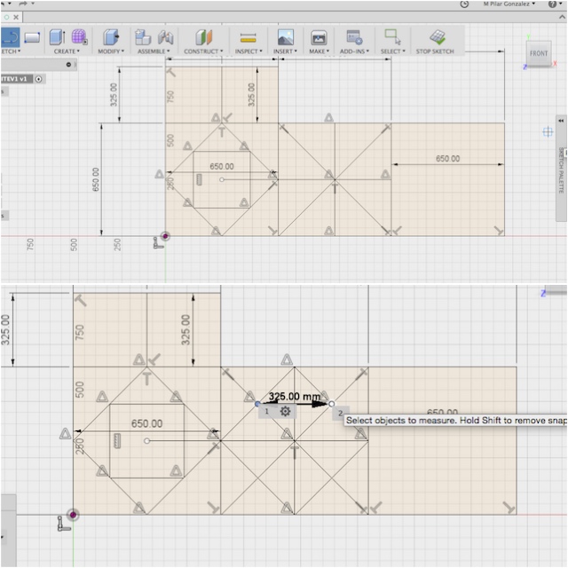
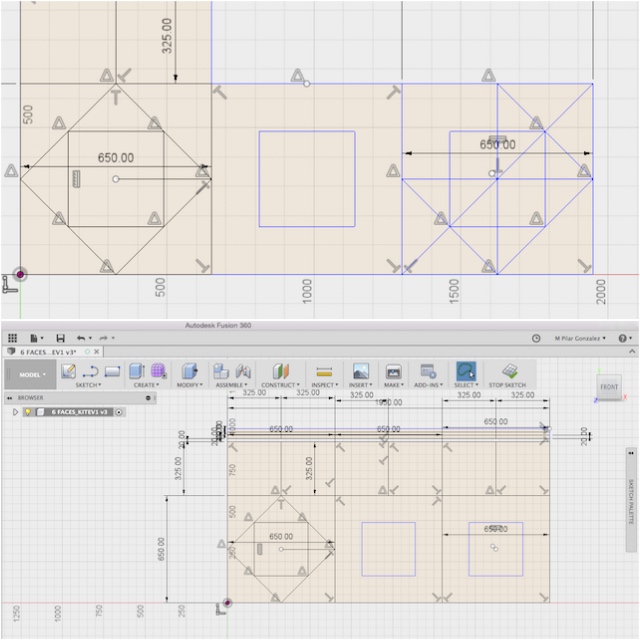
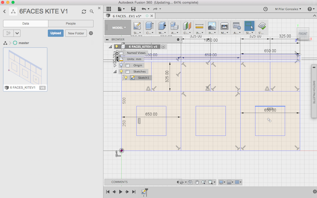
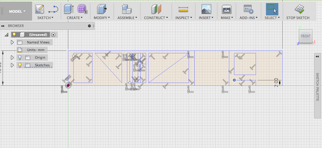
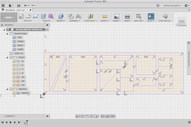
2D - PATTERNS Fusion 360º
6 FACES (Madrid version): Parametric Design
Now i know that my future students can make their patterns using different softwares as Open Sources (tinkerCAD), obviously depending the software used the design process involve one or another processes.
LASER TESTER DESIGNS:
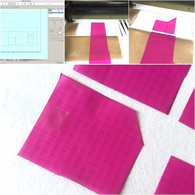
One of the essential materials of the kite is the Nylon Ripstop fabric found in the Fab Academy inventory, but my kite should to be ultra - light so I decided to use Nylon Icarex. This material had not been cut before in our fablab. So I established a series of new parameters that will surely serve any student who needs it. You can know more about these testers visiting the : Final Project Process Page laser tester section.
To make this tests on fabrics also made a series of random designs for set parameters at Laser Cutter Machine :
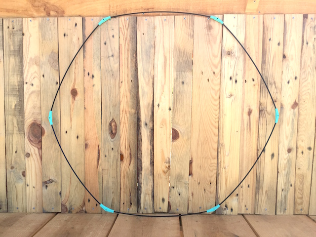
THE 3D´S KITE DESIGN
The design of the 3D kite does not have the dihedral connectors because when i made the design they were not yet finished. For the process i used the autoCAD tool since when exporting my .dxf with the patterns from Fusion 360º i had lost some lines. The model includes the 3D design of the box mentioned later and follow the process practiced during the Academy in weeks when i was trying with Cinema 4D.
3D KITE DESIGN LEARNED TO ME HOW TO SEW THE PATTERNS, HOW TO MEASURES NEW KITES, HOW TO MADE THE MAIN PARTS SO I GAINED HOW TO MAKE DIFFERENT KINDS OF CONNECTORS OR BOX FOR ASSEMBLED THE ELECTRONICS.
Faito v.01_ 6 FACES (Madrid version) AutoCad:

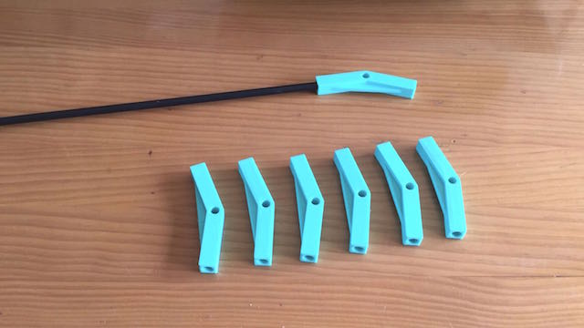
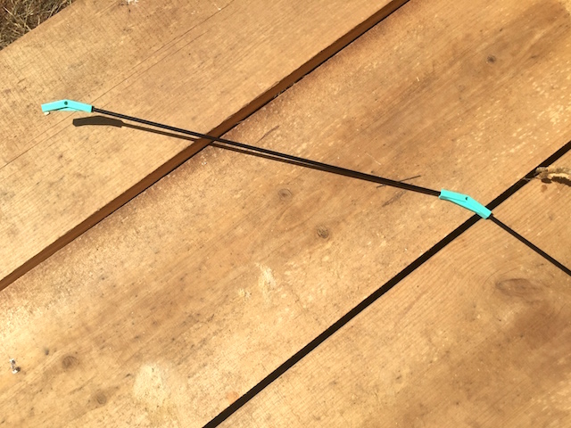
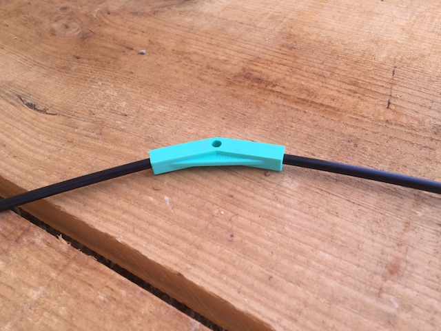
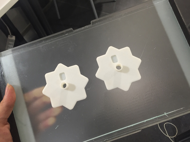
MECHANNISM - PARTS :
My prototype has essential mechannisms that work as connectors giving flexibility to carbon fiber tubes. These connectors are in the center rod and the sides. In the molding and casting week, i decided to begin a design for an 8mm rod that i could adapt it designing another part that would allow me to perform flights without integrating the electronics first so i designed a hub adapter with openScad.
CONNECTORS DESIGN LEARNED TO ME HOW TO MADE AN APPROPIATE MECHANNISM FOR MADE THE FIBER CARBON TUBES MORE FLEXIBLES, USING BOOLEAN FUNCTIONS AND FOLLOWING SUBSTRACTIVE TECHNIQUES FOR EVERY PROCESSES SO I GAINED HOW TO MAKE DIFFERENT KINDS OF CONNECTORS.
CONNECTORS : Can be designed with Open Sources such as OpenScad, TinkerCad or commercials as Cinema 4D
The Kite have 3 main connectors :
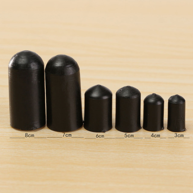
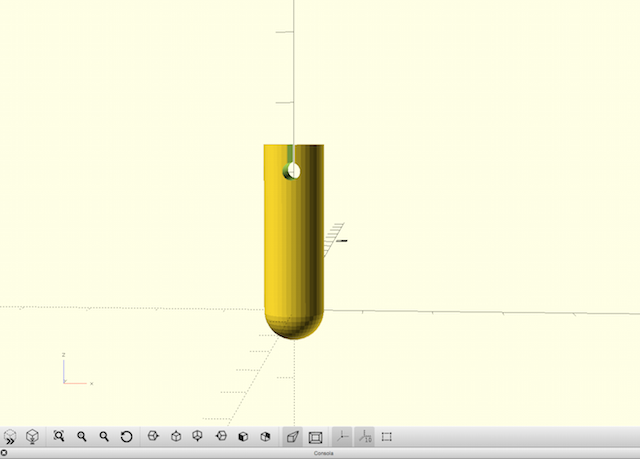
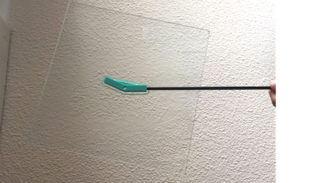
THE ADAPTOR CAP
Here is a reference that i founded at the market about the design :
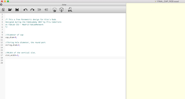
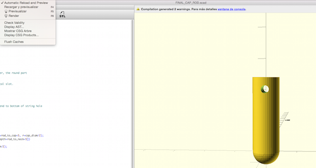
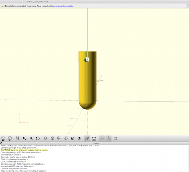
And here the processes followed for design one at OpenScad :
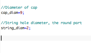
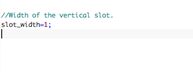
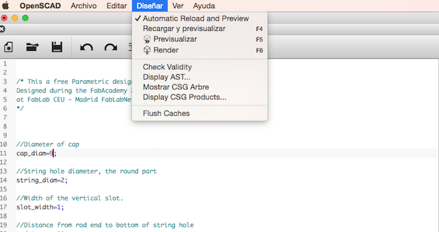
1. First of all i was making some variables about the measures about the cap, the string and the distance between the vertical slot:
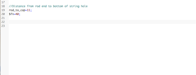
2. Later the distance from the edn of the rod to the botton of the string hole :
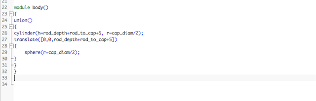
3. I wrote some functions, the first about the body, creating the cylinder and the sphere :
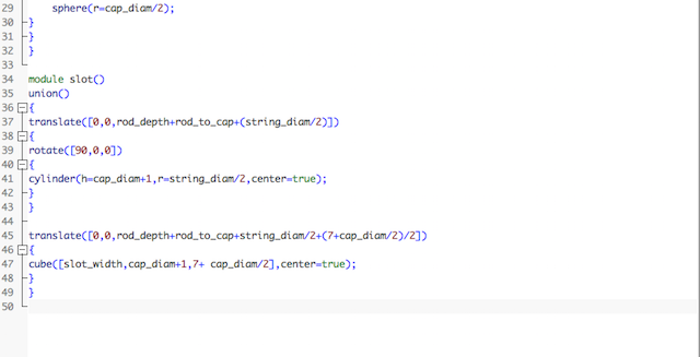
4. The second about the slot :
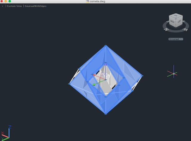
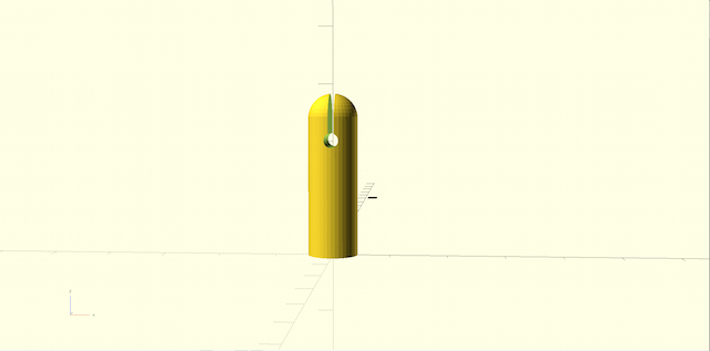
5. For finnish i made a previsualization for see everything was working :
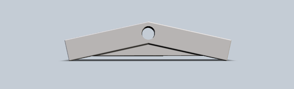
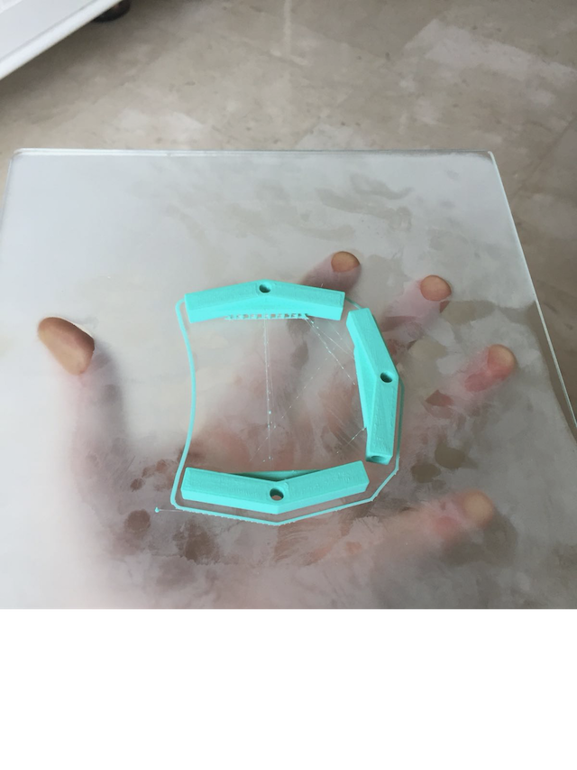
THE DIEDROS
The other important design were the "Diedros", i couldn´t to find some references about it so the design involve me in a harder process for finish them in time.
I was trying some attempts described at my Final Project Process page, as i mentioned there now i have the diedro´s family but for the prototype presented to Neil i use this :
For now more about the start design for the main rod, you can go to this pages :
UPDATES
The last design i made but i couldn´t to presented was about how to integrate the electronics better so here is a video-render with the idea :
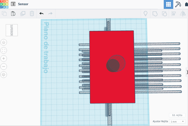
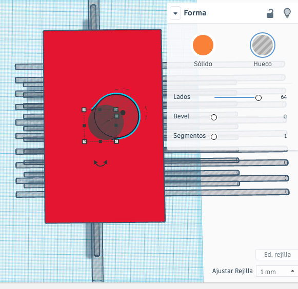
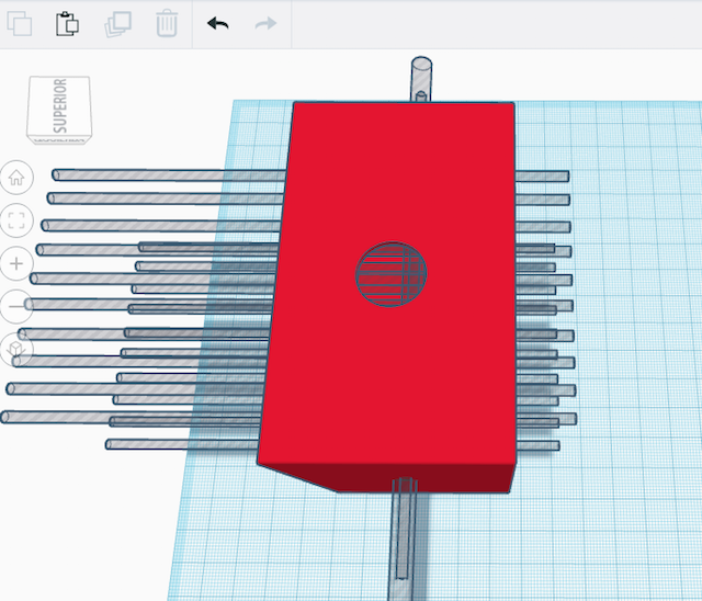
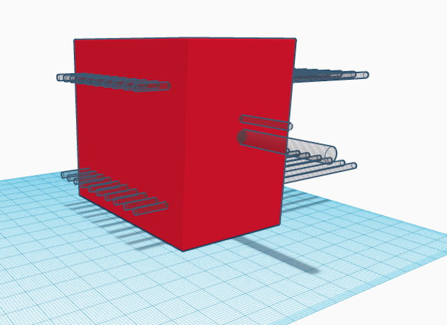
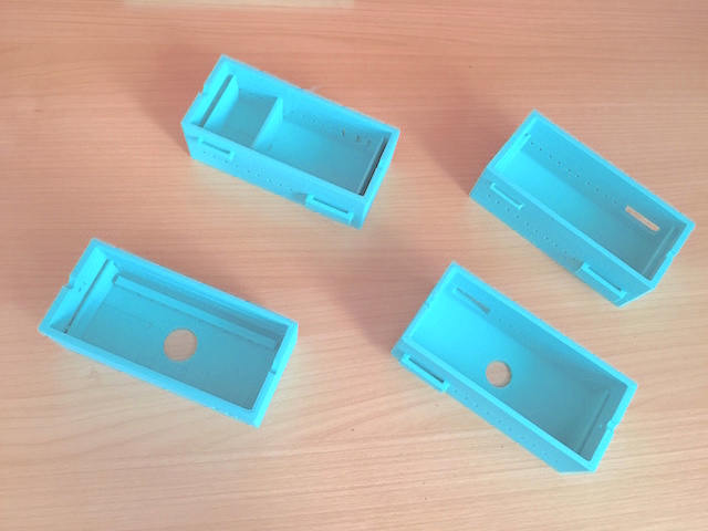
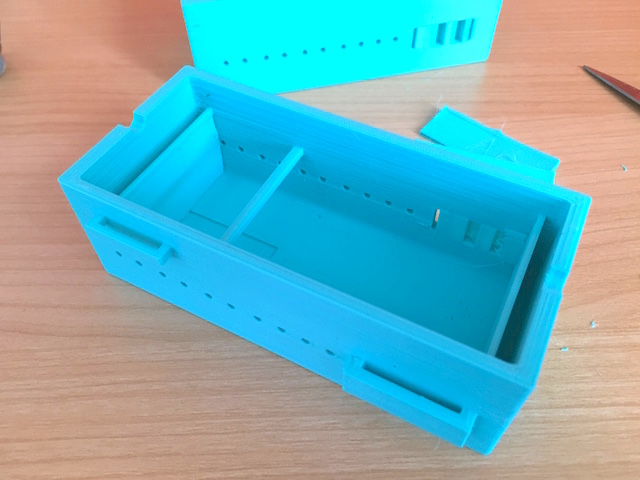
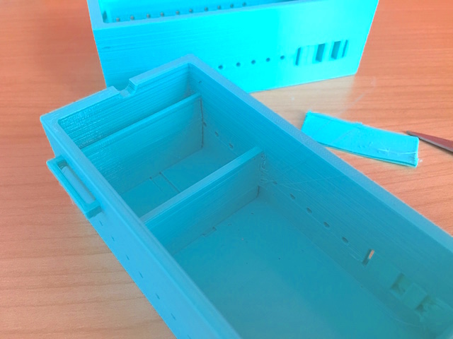
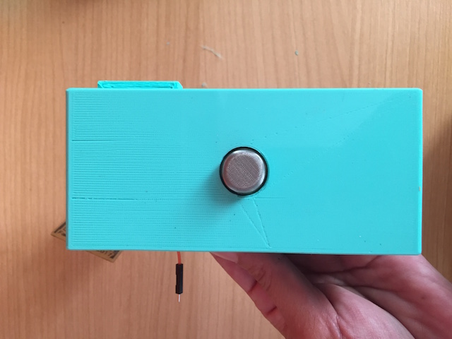
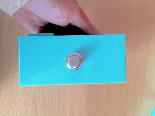
THE BOX FOR ELECTRONICS
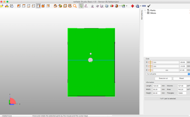
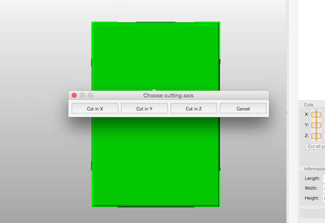
The BOX The initial design about the "Box" which integrates the electronics at my prototype, was manufactured in the laser cutting machine with the idea to use a light material such as balsa wood, (If you want to know more about this design processes just take a look to the Interface and Applications WEEK
16) when i made the 2D and 3D design after i finnished my assignment week:
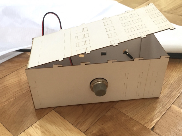
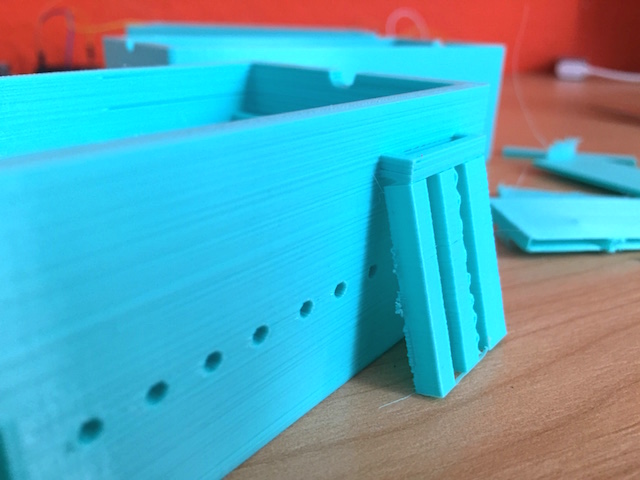
But for time´s reasons i had to redesign a box that contemplated a minimum properties as the weighth, very small and could be opened for to show the interior. Rapid prototype that would need more than one attempt but that initially as my instructors would serve for the presentation. Also is an important part which should to be designable by kids :
2nd ATTEMPT : The TinkerCAD attempt follow the addign and substractive techniques learned during the diploma but obviously is a basic design:
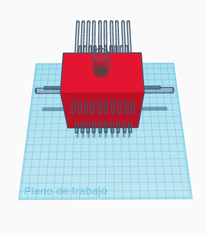
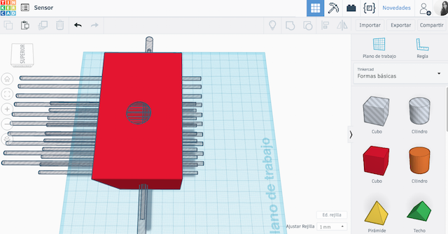


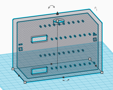
For make a quick cut to the 3D Model i used fabnect :
TECHNOLOGIES INVOLVES : FABRICATION
For the manufacture of the prototype i have used various tools such as Laser Cutting machine, 3D Printers, Milling Machine and Sewing Machine each of these technologies involves the knowledge adcquired during each week but as i was involved in new processes a could to learn new things.
TECHNOLOGIES USED DURING THE DEVELOPE LEARNED TO ME HOW TO PRACTICE THE NEW SKILLS AT THE MACHINES LEARNED DURING THE DIPLOMA. HOW TIME I CAN TO SPENT IF EVERY THING GO WELL?
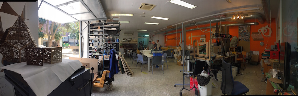
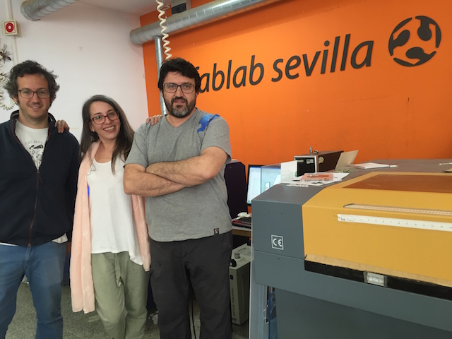
LASER CUTTER MACHINES: This technology made precise my patterns fastly for sew without problems. I had the opportunity to try some kinds of models of them. We have some differents laser machines at CEU but i had the opportunity to use other machines from other fablabs such as the IED Fablab and Sevilla Fablab during my greatings visits there.
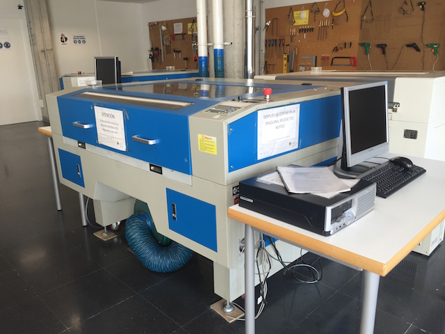
At the manufacturing process on the laser cutting machine, made several testers. After the study and practices with different materials such as paper, cotton fabrics, nylon ripstop and nylon icarex for several weeks, finally i got the appropriate parameters to make a clean cut without burns or stains and perform my fabrics properly.
To cut my patterns i had the opportunity to visit the FabLab of the Institution where i work (IED FabLab) and that i had not been able to visit until the moment. They was really interested in my processes so after i commented all parameters used in the CEU Laser Machine, we was ready for Cut my patterns with success. Now they have in their library parameters new ones for new materials.
This was the parameters used at Fablab CEU testers commented noticed proper as the last one.
| POWER | SPEED | CORNER POWER |
|---|---|---|
| 60 | 20 | 12 |
| 80 | 16 | 14 |
| 70 | 14 | 11 |
| 40 | 18 | 16 |
The settings for cut the patterns at the IED were something differents because the materials for this time was ICAREX :
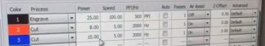
| POWER | SPEED | CORNER POWER |
|---|---|---|
| 10.00 | 5.00 | 2000 Hz |
3D PRINTERS MACHINES : Made Mechanisms described at Design section.
3D PRINTERS USE LEARNED TO ME HOW TO FAST I CAN MADE PRECISE AND REPEATED TASK, HOW I MUST TO SIMPLY THE DESIGNS,TOLERANCES FOR don´t MISS MATERIAL, NEW FILAMENTS...
FAITO v.01: 3D Printer Processes from Pilu Caballero on Vimeo.
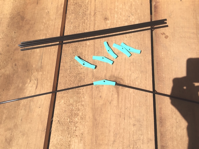
I made same testers with low quality first for decide which model would to be better and calculate the machine´s tolerances for redesign the piece which finally i used :
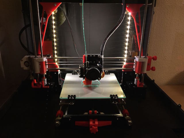
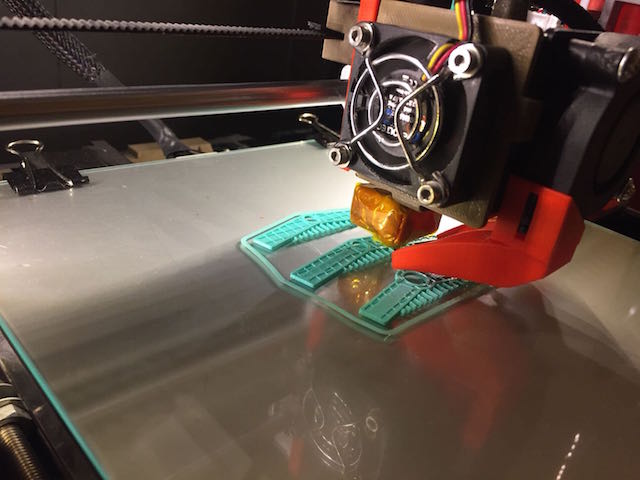
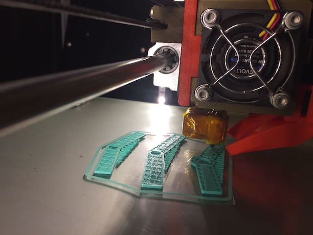
After this testers i printed the final product making one first with low quality for be sure about flexibility :
and here are the six connectors for every carbon fiber tube :
after i had the diedro connectors i decided to assemble the kite for ckeck is everything is ok :
Here is the final results after some attempts printed :
Here is the final results after some attempts printed :
About the Star for the rod this was the result:
THE BOX
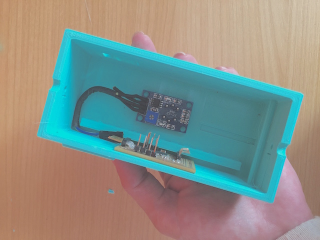
The box for assembled the electronics had some fabrications attempts because must to assembled the electronics so here was the final result :
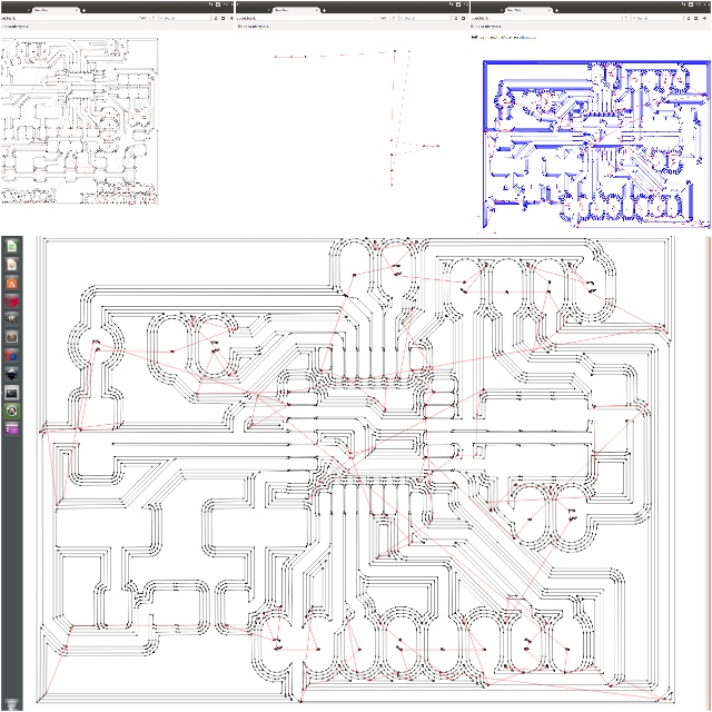
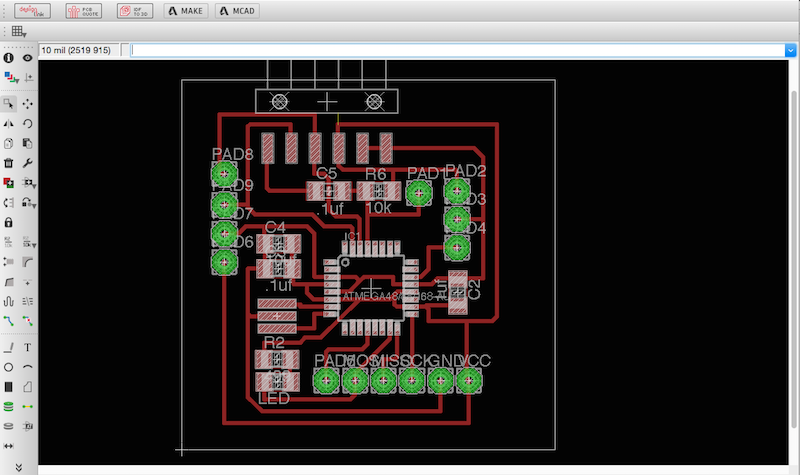
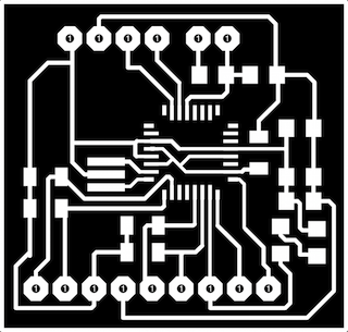
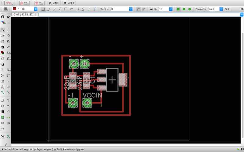
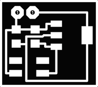
MILLING MACHINE PROCESSES: I used the Modela MDX20 described during the Academy for mill the boards following the same practices made at every week i milled a board or boards.
The process was without problem so i had my boards quick for work with them.
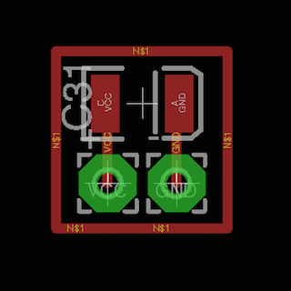
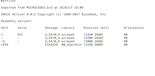
During the final project week i milled the board designed for wire the bright leds, the boards for my power supply based in the use of ion lithium batteries, also milled the mini boards for each led...
THE MODELA LEARNED TO ME HOW TO BE CAREFULL WITH THE PROCESSES, HOW TO USE FABMODULES OR FABMODS IN DEPTH FOR PREPARE FILES, ABOUT COMMUNICATIONS PROTOCOLOS, ABOUT MEASURES FOR DESIGN, ABOUT DIFFERENTS MILLS,HEADERS AND HOW TO SOLVE PROBLEMS WITH TRICKS AND TIPS.
Faito v.01 : Electronics Processes from Pilu Caballero on Vimeo.
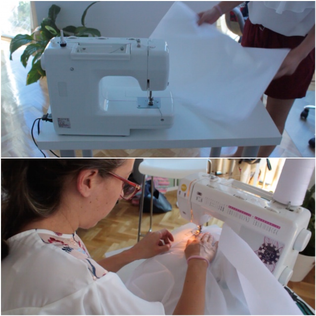
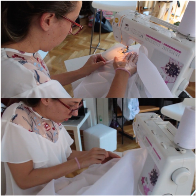
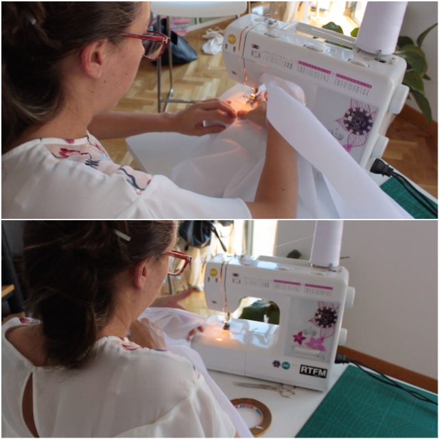
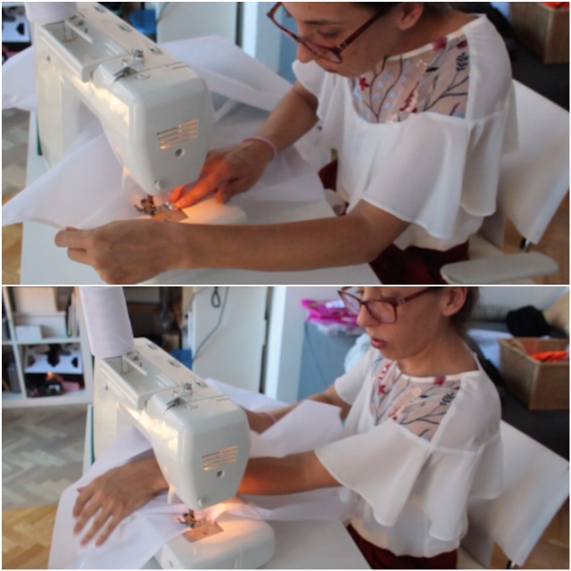
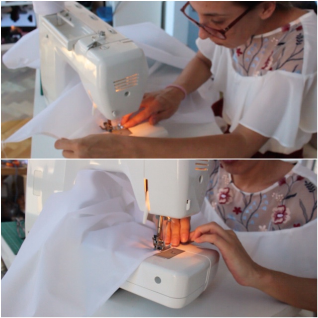
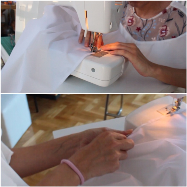
SEWING MACHINE:
Sewing processes had some previous attempts during my academy for be sure that i didn´t miss nothing or damage the Icarex. Is a delicate fabric when you sew but robust and resistant once the sew is finnished. For the final prototype i followed some steps, first of all i sewed the hems and allowances using double side adhesive tape at every side.
ELECTRONICS : Turn Faito to an interactive Kite
THE ELECTRONICS LEARNED TO ME HOW TO USE POWER REGULATORS FOR ION LITHIUM BATTERY SUPPLIES, HOW TO READ DATASHEET, HOW TO USE CAPACITORS RECOMENDDED, HOW TO USE A DIFFICULT SENSOR, HOW TO USE 3000 LUM 3V BRIGHT LEDS, HOW TO DESIGN MASTERS AND SLAVES. HOW TO DESIGN THE BOARDS FOR THE NEXT MODELS.
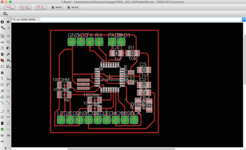
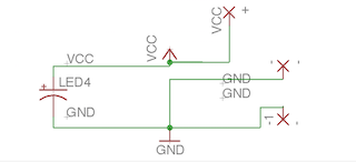
Faito v.01 have some boards inside designed with Eagle following the processes learned during the Academy, the idea is to add more sensors in the future and assembled the wires with soft circuits techniques using materials such as conductive threads. In order to make the kite sewable, the design of the boards will must to consider this.
Other sensors could to be add such as temperature sensor, humidity or light dependent resistors.
For the moment the electronics are :
1. A Master Board with an Input : MQ 135 An analog sensor (very difficult for work with it)
2. An Slave with Outputs : Bright leds 3v / 3000 lm
3. Tiny boards for assembled for 3000 Lum 3v Bright Leds
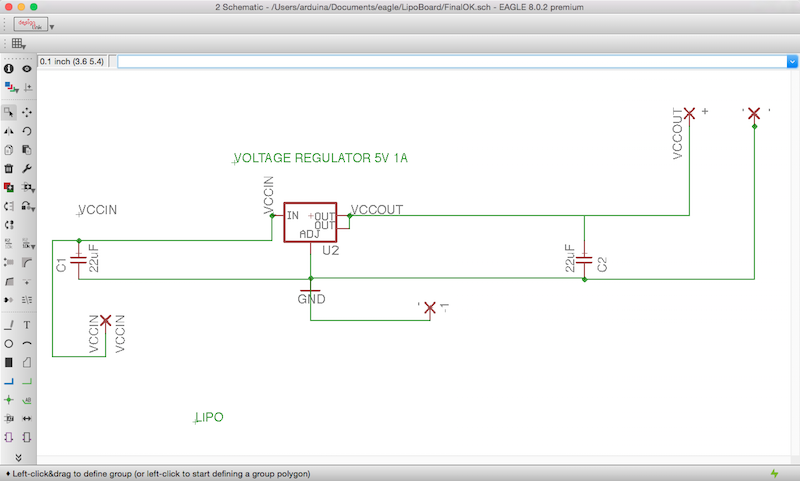
3. A Board for Power Supply : Voltage regulator for Lithium Ion Batteries (both connected in parallel)
DESIGN
MASTER
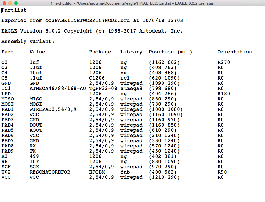
The board where is attached the Co2 Sensor was designed and fabricated at Networking and Communications Assignment week, a micro-processor board based in the fabKit with some modifications. I used a 168 Atmega microprocessor with a 8mhz resonator, with a blue led attached to the MOSI pinout for make some communications testers first and an analog pin for the data sensor and a digital pin for future connections with the 433Mhz TRANSMITTER module. Also i respected the TX and RX pins for use in case that the wireless communication with the 433Mhz trasnmitter not work correctly. If you want to know more about the design and fabrication process check the link : WEB i explained further.
THE RECEIVER and HIS TINY BOARDS
The RECEIVER was a board designed and fabricated during the week for the final project so the idea was continue to using the same microprocessor Atmega 168 i decided to redesign the LedBoard designed during the Output Device Week but with some moddifications thinking i assembled the leds outside the box.
This board couldd to be connected in both ways, as a simply communication serial with wires and as i commented with the properties to be wireless with the 433Mhz RECEIVER module described at the Networking and Communications week.

The leds are assembled at the kite so here are the tiny boards for them :
The board for the array :

During the Project development week i also designed the led´s boards for the Receive Board and the Power Supply boards.
Boards for each led attached :
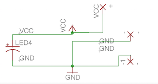


POWER SUPPLY
I connected 2 Lipo Power Supllies 3,7v 1150 mA each one, so i decided design a Lipo Board with a 5V Voltage Regulator from the fablab inventory :


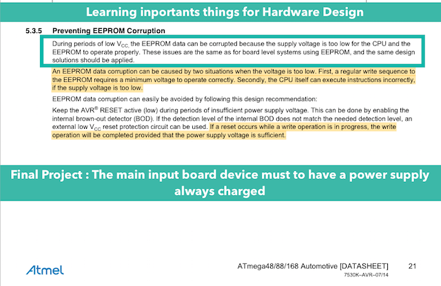
THE ATMEL 168P DATASHEET: THINGS I LEARNED AND HOW IT HELPED TO ME?
I learned a lot during the Diploma reading this Datasheet used in other assignments such as : Output Devices, Input Devices, Networking and Communications and Interface and Applications so for this part, i extxracted some simply things that helped to me a lot with the final programs for store the sensor values at EPPROM MEMORY.
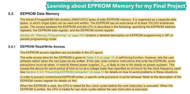
And here you can to navigate beetwen his three hundreds pages where i was making my anotations in parts used during the Diploma at Input Devices Assignment, Output Devices and Interface week.
EMBBEDED PROGRAMING : Interface Pollution Data Values for use to Teach and Learn HOW TO RESPECT THE ENVIRONMENT
Faito v.01: Programing Processes from Pilu Caballero on Vimeo.
THE PROGRAMMING LEARNED TO ME HOW TO MADE A BASIC NETWORKING, HOW TO READ SENSOR VALUES, HOW TO USE APROPIATE VALUES FOR SEND TO SLAVES, HOW TO USE TEH DATASHEET FOR CODE, HOW CAN TO BE PROGRAMMED BY KIDS AND OPENED THE PROCESS FOR STORE DATA VALUES WITH THE USE TO EPROM MEMORY.
INPUT DEVICES send information data to OUTPUT DEVICES for Flash Bright Leds described at Electronics section.
So i had this Programing Files :
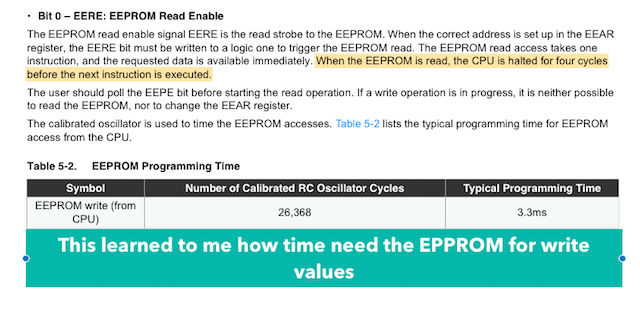
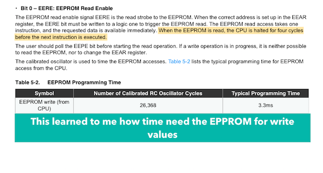
Faito Kite as i mentioned store data from the sensor during the flight so for this i use EPPROM memory from my processor for write there them and read when the kite stop his flights. For that i programmed some codes for send and receive the values trought the boards and another for read the values at my computer.
The micro-processor on any AVR based board has EEPROM: memory whose values are kept when the board is turned off (like a tiny hard drive). This library enables you to read and write those bytes. As i learned trought the Datasheet, my processor have 512 bytes on memory so the capability is limited.
The main functions used were :
EEPROM Read : Read the EEPROM and send its values to the computer troght monitor serial.
EEPROM Write : Stores values from an analog input to the EEPROM.
EEPROM Update : Stores values read from A0 into EEPROM, writing the value only if different, to increase EEPROM life.
Another library used of, course was software serial described before.
So here are the programms worked :
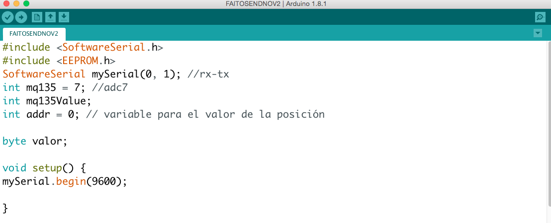
FAITO SEND AND WRITE AT EPPROM MEMORY
#include < SoftwareSerial.h>
#include <EPPROM.h>
SoftwareSerial mySerial(0, 1); //rx-tx
int mq135 = 7; //adc7
int mq135Value;
int addr = 0; // variable para el valor de la posición
byte valor;
void setup() {
mySerial.begin(9600);
}
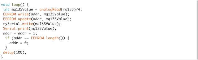
void loop() {
int mq135Value = analogRead(mq135)/4;
EEPROM.write(addr, mq135Value);
EEPROM.update(addr, mq135Value);
mySerial.write(mq135Value);
Serial.print(mq135Value);
addr = addr + 1;
if (addr == EEPROM.length()) {
addr = 0;
}
delay(100);
}
As you can see i divided the Input Sensor value by 4 for have the data in bytes for store at the EPPROM memory.
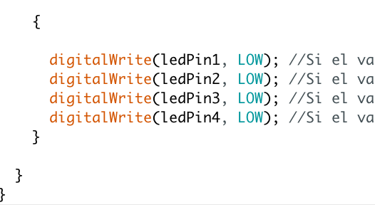
FAITO RECEIVE AND ACTIVATE LEDS
With this progamm the led board detect if the datas incoming from serial all availables and turn ON the array leds according an input i had previously studing the sensor.
#include <SoftwareSerial.h>

SoftwareSerial mySerial(0,1);

int input;
int ledPin1 = 5;
int ledPin2 = 6;
int ledPin3 = 9;
int ledPin4 = 10;

int brightness;

void setup() {
  mySerial.begin(9600);
}

void loop() {


  if (Serial.available()>0){

  input=Serial.read();

  if (input <'75'){

      digitalWrite(ledPin1, HIGH); //Si el valor de input es 1, se enciende el led
      digitalWrite(ledPin2, HIGH); //Si el valor de input es 1, se enciende el led
      digitalWrite(ledPin3, HIGH); //Si el valor de input es 1, se enciende el led
      digitalWrite(ledPin4, HIGH); //Si el valor de input es 1, se enciende el led
    }

    else

    {

      digitalWrite(ledPin1, LOW); //Si el valor de input es diferente de 1, se apaga el LED
      digitalWrite(ledPin2, LOW); //Si el valor de input es diferente de 1, se apaga el LED
      digitalWrite(ledPin3, LOW); //Si el valor de input es diferente de 1, se apaga el LED
      digitalWrite(ledPin4, LOW); //Si el valor de input es diferente de 1, se apaga el LED
    }

  }
}
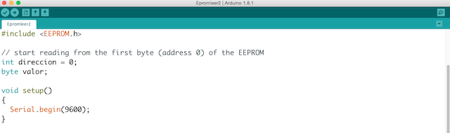
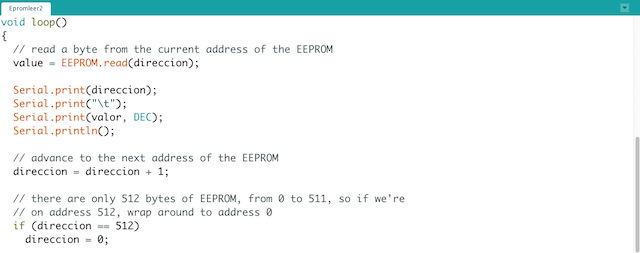
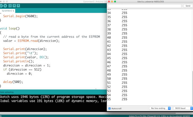
EPPROM READ DATA BYTES
This the program for read the data stored during the flights which print at monitor serial the data incoming from the sensor in bytes.
#include <EEPROM.h>

// begin reading from the first byte (address 0) of the EEPROM

int direccion = 0;
byte valor;

void setup(){
  Serial.begin(9600);
}

void loop(){
                                    // read a byte from the current address of the EEPROM
  value = EEPROM.read(direccion);

  Serial.print(direccion);
  Serial.print("\t");
  Serial.print(valor, DEC);
  Serial.println();

                                    // advance to the next address of the EEPROM
  direccion = direccion + 1;

                                    // there are only 512 bytes of EEPROM, from 0 to 511, so if we're
                                   // on address 512, wrap around to address 0
  if (direccion == 512)
    direccion = 0;

  delay(500);
}

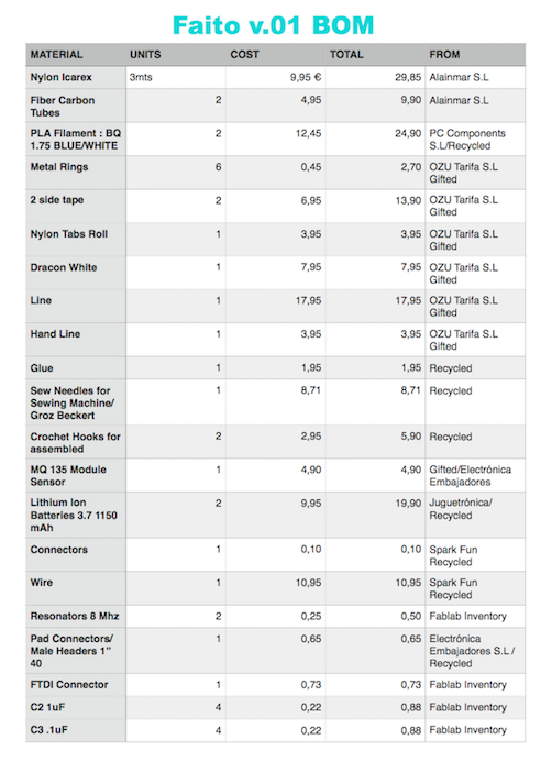
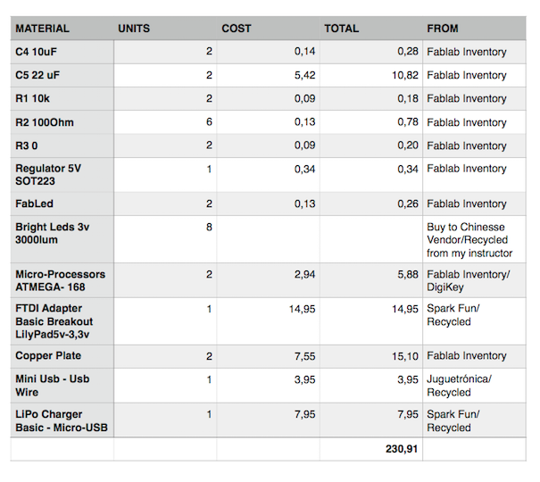
BOM : The bill of Materials
As i mentioned in the WEEK 17 the budget was reduce thanks to the support of a mini partner so here is the real if this opportunity didn´t to be able.
LICENSE
Faito v.01 have a Creative Commons License explained at my Intellectual Property Page :
THINGS LEARNED
First of all, as i made an intensive research, i learned lot references about Kites: Types, models,researches, looking in what ways make sense to continue....