Fourteenth Week
NETWORKING AND COMMUNICATIONS
| HAVE YOU | TASK COMPLETED |
|---|---|
| Described your design and fabrication process using words/images/screenshots | YES |
| Explained the programming process/es you used | YES |
| Outlined problems and how you fixed them | YES |
| Included original design files and code | YES |
NEIL´S LESSON
Index
- WEEK TASK : For the week´s assignment the goal is :This Week the goal is learned about networking and communications making a network wired or not with 2 microprocessors.
- Updates and Group Projects : Wireless communication with transmiters and recivers modules
- Files
- My Week Problems Solved
- Things I Learned
- My Week Conclusions
- My Final Project
This Week the goal is learned about networking and communications making a network wired or not with 2 microprocessor at list. So I decided work on my final project practicing communications between boards trying to create a symbiotic system
After the class in order to understand how to make a network with my boards, i decided to learn about "Serial Communication" so i decided research a bit founding some useful to tutorials such as :
From there i made a sumary about the main concepts.
THE DIFFERENCE BETWEEN PARALEL AND SERIAL
In order for those individual circuits to swap their information, they must share a common communication protocol. Hundreds of communication protocols have been defined to achieve this data exchange, and, in general, each can be separated into one of two categories: parallel or serial.
Parallel interfaces transfer multiple bits at the same time. They usually require buses of data - transmitting across eight, sixteen, or more wires. Data is transferred in huge, crashing waves of 1’s and 0’s.
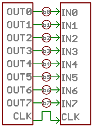
An 8-bit data bus, controlled by a clock, transmitting a byte every clock pulse. 9 wires are used.
Serial interfaces stream their data, one single bit at a time. These interfaces can operate on as little as one wire, usually never more than four.
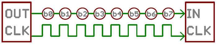
Think of the two interfaces as a stream of cars: a parallel interface would be the 8+ lane mega-highway, while a serial interface is more like a two-lane rural country road. Over a set amount of time, the mega-highway potentially gets more people to their destinations, but that rural two-laner serves its purpose and costs a fraction of the funds to build.
Parallel communication certainly has its benefits. It’s fast, straightforward, and relatively easy to implement. But it requires many more input/output (I/O) lines. If you’ve ever had to move a project from a basic Arduino Uno to a Mega, you know that the I/O lines on a microprocessor can be precious and few. So, we often opt for serial communication, sacrificing potential speed for pin real estate.
THE DIFFERENCE BETWEEN ASYNCHRONOUS or SYNCHRONOUS SERIAL
Each serial interfaces can be sorted into one of two groups: synchronous or asynchronous.
THE MECHANISM FOR ESCHEWING THE EXTERNAL CLOCK SIGNAL
THE INPORTANCE OF THE BAUDRATE
The baud rate specifies how fast data is sent over a serial line. It’s usually expressed in units of bits-per-second (bps). If you invert the baud rate, you can find out just how long it takes to transmit a single bit. This value determines how long the transmitter holds a serial line high/low or at what period the receiving device samples its line.
The only requirement is that both devices operate at the same rate. One of the more common baud rates, especially for simple stuff where speed isn’t critical, is 9600 bps.
UNDERSTANDING SYNCHRONIZITATION AND PARITY BITS
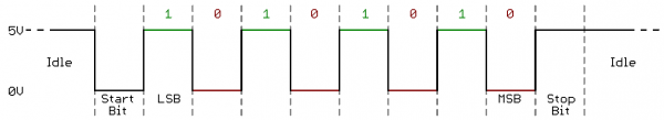
The synchronization bits are two or three special bits transferred with each chunk of data. They are the start bit and the stop bit(s) these marks the begining and end of a packet of data.
Parity is a form of very simple, low-level error checking. It comes in two flavors: odd or even. To produce the parity bit, all 5-9 bits of the data byte are added up, and the evenness of the sum decides whether the bit is set or not. For example, assuming parity is set to even and was being added to a data byte like 0b01011101, which has an odd number of 1’s (5), the parity bit would be set to 1. Conversely, if the parity mode was set to odd, the parity bit would be 0.
A device transmitting the ASCII characters ‘O’ and ‘K’ would have to create two packets of data. The ASCII value of O (that’s uppercase) is 79, which breaks down into an 8-bit binary value of 01001111, while K’s binary value is 01001011. All that’s left is appending sync bits. It isn’t specifically stated, but it’s assumed that data is transferred least-significant bit first. Notice how each of the two bytes is sent as it reads from right-to-left.
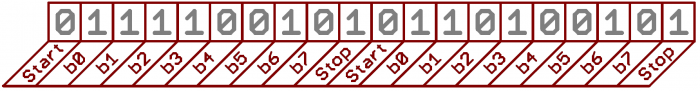
For every byte of data transmitted, there are actually 10 bits being sent: a start bit, 8 data bits, and a stop bit. So, at 9600 bps, we’re actually sending 9600 bits per second or 960 (9600/10) bytes per second.
HOW TO WIRE
A serial bus consists of just two wires - one for sending data and another for receiving. As such, serial devices should have two serial pins: the receiver, RX, and the transmitter, TX.
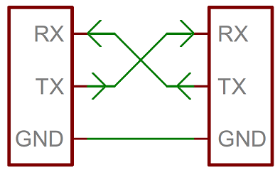
It’s important to note that those RX and TX labels are with respect to the device itself. So the RX from one device should go to the TX of the other, and vice-versa. It’s weird if you’re used to hooking up VCC to VCC, GND to GND, MOSI to MOSI, etc., but it makes sense if you think about it. The transmitter should be talking to the receiver, not to another transmitter.
When microcontrollers and other low-level ICs communicate serially they usually do so at a TTL (transistor-transistor logic) level. TTL serial signals exist between a microcontroller’s voltage supply range - usually 0V to 3.3V or 5V. A signal at the VCC level (3.3V, 5V, etc.) indicates either an idle line, a bit of value 1, or a stop bit. A 0V (GND) signal represents either a start bit or a data bit of value 0.
TTL is much easier to implement into embedded circuits. However the low voltage levels are more susceptible to losses across long transmission lines.
HOW TO CONVERT DATA ON A PARALLEL BUS TO/AND FROM SERIAL INTERFACE
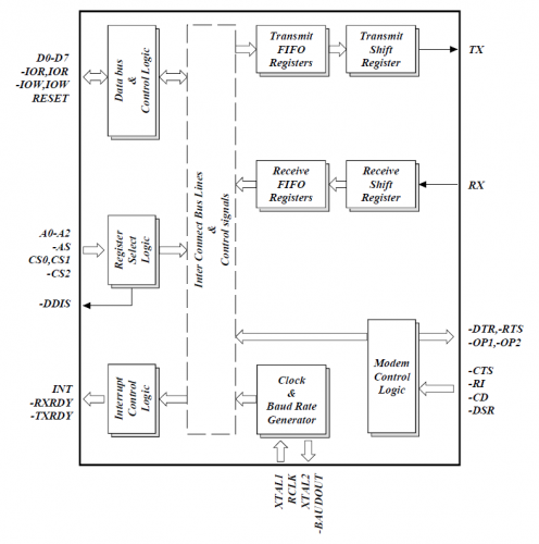
UART, create the serial packets and control those physical hardware lines. A universal asynchronous receiver/transmitter (UART) is a block of circuitry responsible for implementing serial communication. Essentially, the UART acts as an intermediary between parallel and serial interfaces. On one end of the UART is a bus of eight-or-so data lines (plus some control pins), on the other is the two serial wires - RX and TX.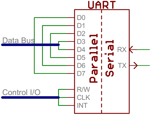
As the R and T in the acronym dictate, UARTs are responsible for both sending and receiving serial data. On the transmit side, a UART must create the data packet - appending sync and parity bits - and send that packet out the TX line with precise timing (according to the set baud rate). On the receive end, the UART has to sample the RX line at rates according to the expected baud rate, pick out the sync bits, and spit out the data.
If a microcontroller doesn’t have a UART (or doesn’t have enough), the serial interface can be bit-banged - directly controlled by the processor. This is the approach Arduino libraries like SoftwareSerial take.
BUS CONTENTION
Serial communication is designed to allow just two devices to communicate across one serial bus. If more than one device is trying to transmit on the same serial line you could run into bus-contention.
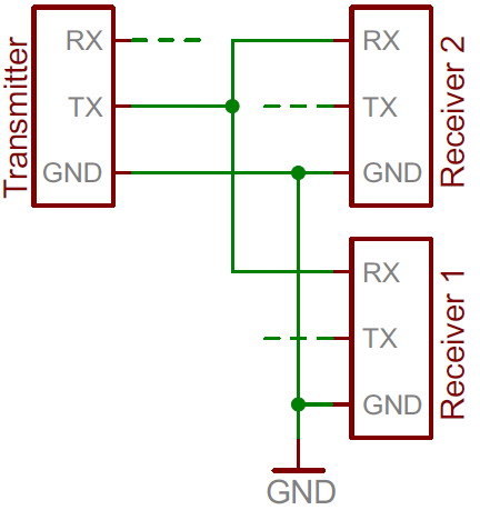
Two devices trying to transmit data at the same time, on the same line, is bad! but it can be safe to connect multiple receiving devices to a single transmitting device.
For example, My board’s TX is already connected to the USB programmer’s RX line and i want to connect my CO2 sensor board to the board i will connect his RX to my TX board.
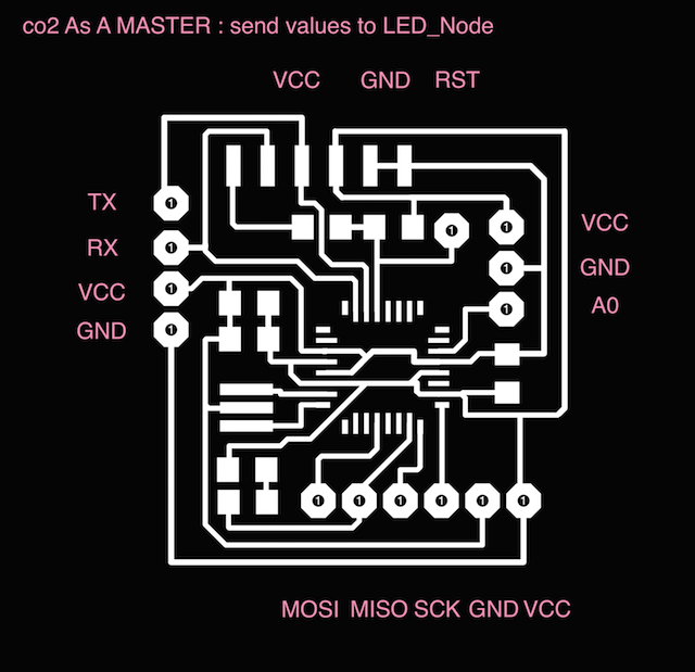
THE MASTER : Send values to the Slave or Slaves
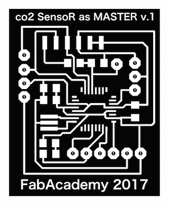
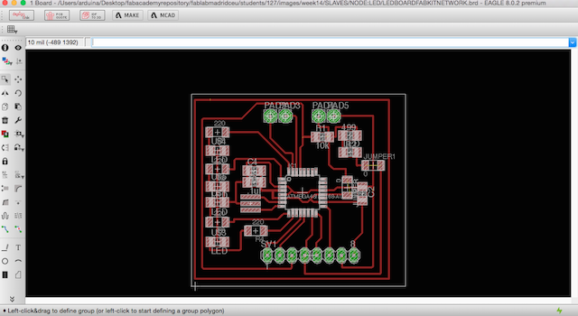
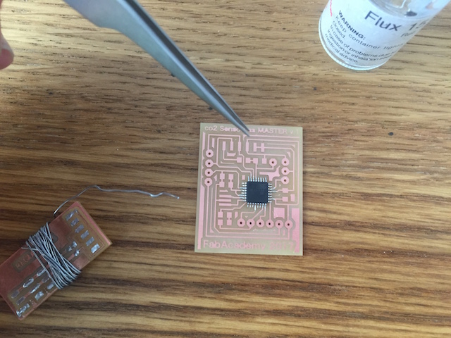
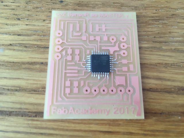
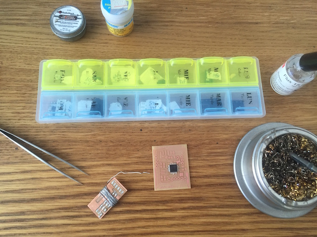
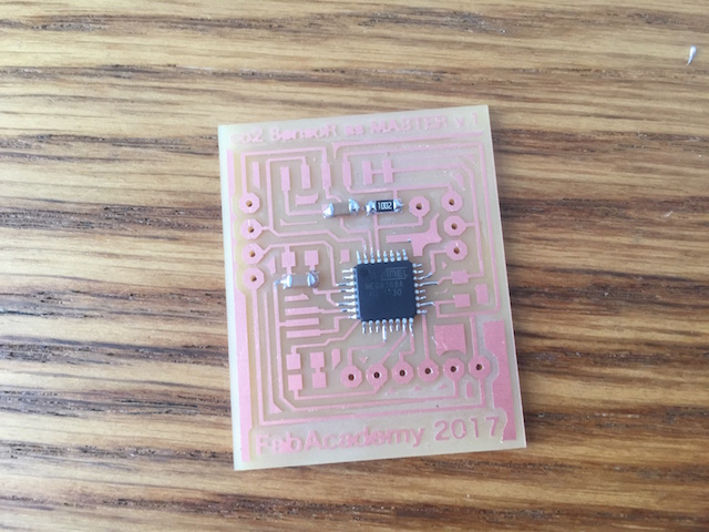
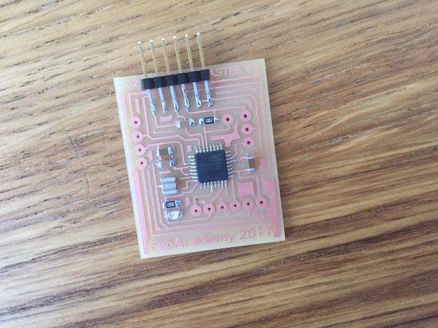
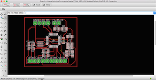
1. In order to advance with my final project, i designed the Input Board (Co2 Sensor based in FabKit v.04)
for use as a MASTER for send values to the LED_NODE 2, first. The process was easy because just had to add the pad for make more TX and RX connections and changed the Led to MOSI for have indications when connections be success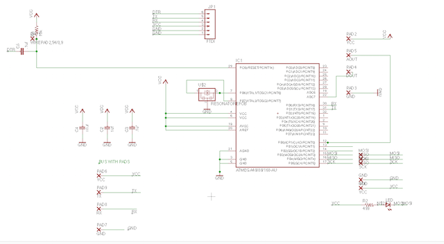
2. As want to have some Powers, i conserved the FTDI connections for program the boards with my computer.

3. When i finished, exported my BOM list for buy the components later.
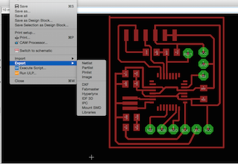
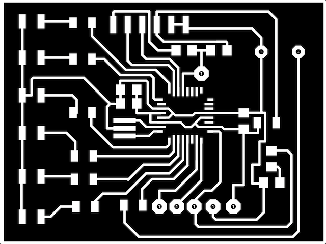
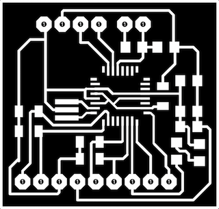
4. An export Image as .png with 1500 dpi resolution and Monochrome.


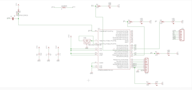
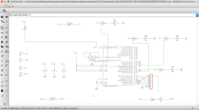
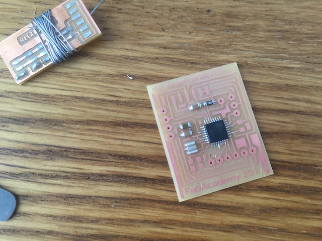
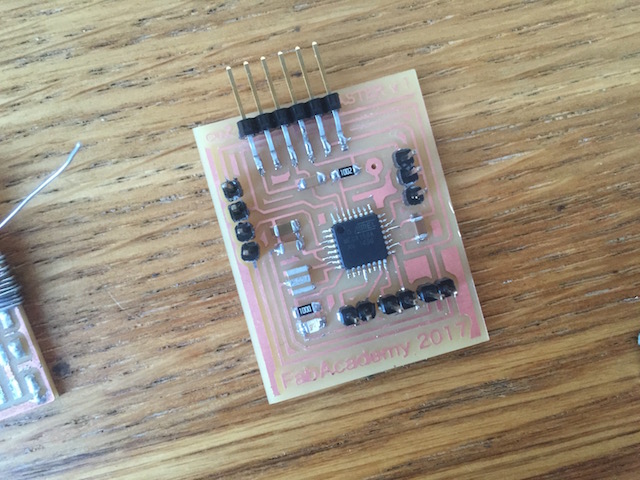
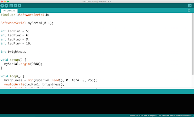
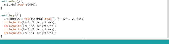
THE SLAVE : My idea is to receive Values from the Master acording to a range maped previously.
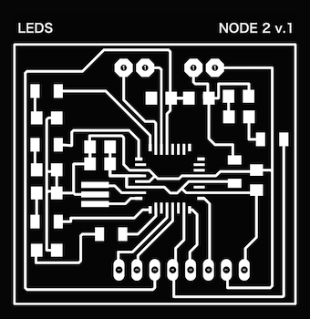
I made a design based in the board fabricated at the Output Devices Assigment Week
OUTPUT Design
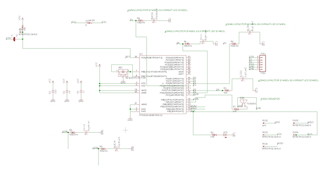
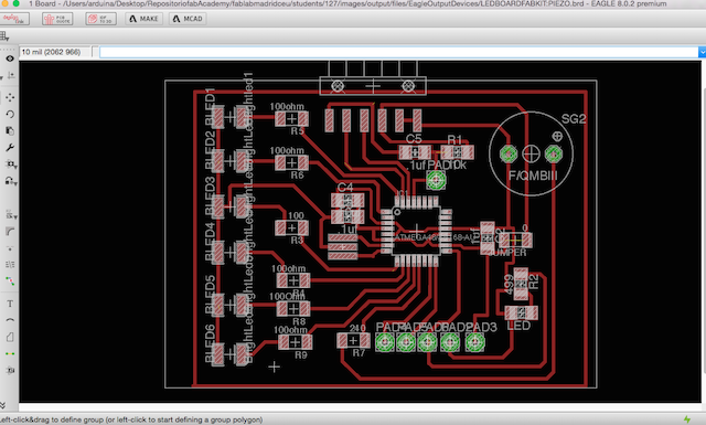

So here are my Eagle Project with different leds but using the same micro-processor with the idea to continue with the datasheet study.


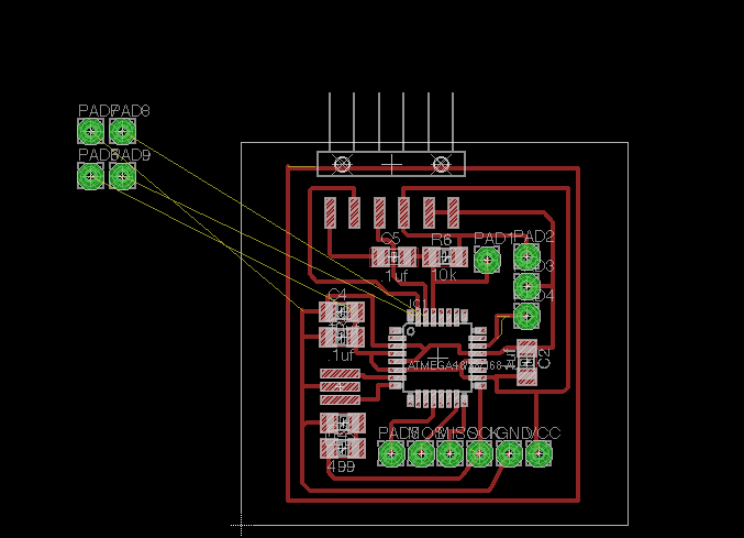
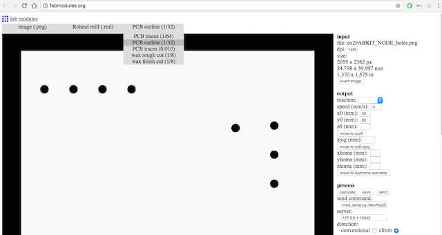
1. Imported my Interior File for mill with 1/64 mill at fabmodules :

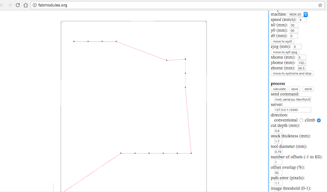
2. Calculating for check things and take a preview about how the mills work :

3. Mill Results:

4. Later i repeated the same operation but changing the mill by a 1/32 one.

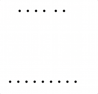
5. Imported my holes file and cuted the board :

6. For finish, i improted the Outlines File with the same mill :

7. For each board i repeated the same process, after this i have new board for communicate between both.
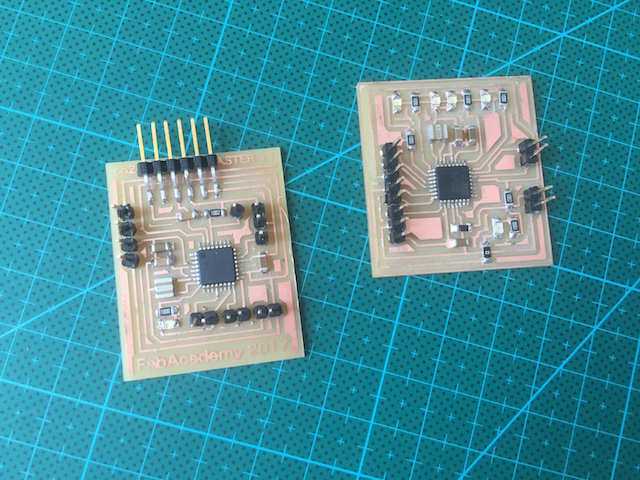
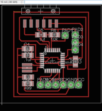
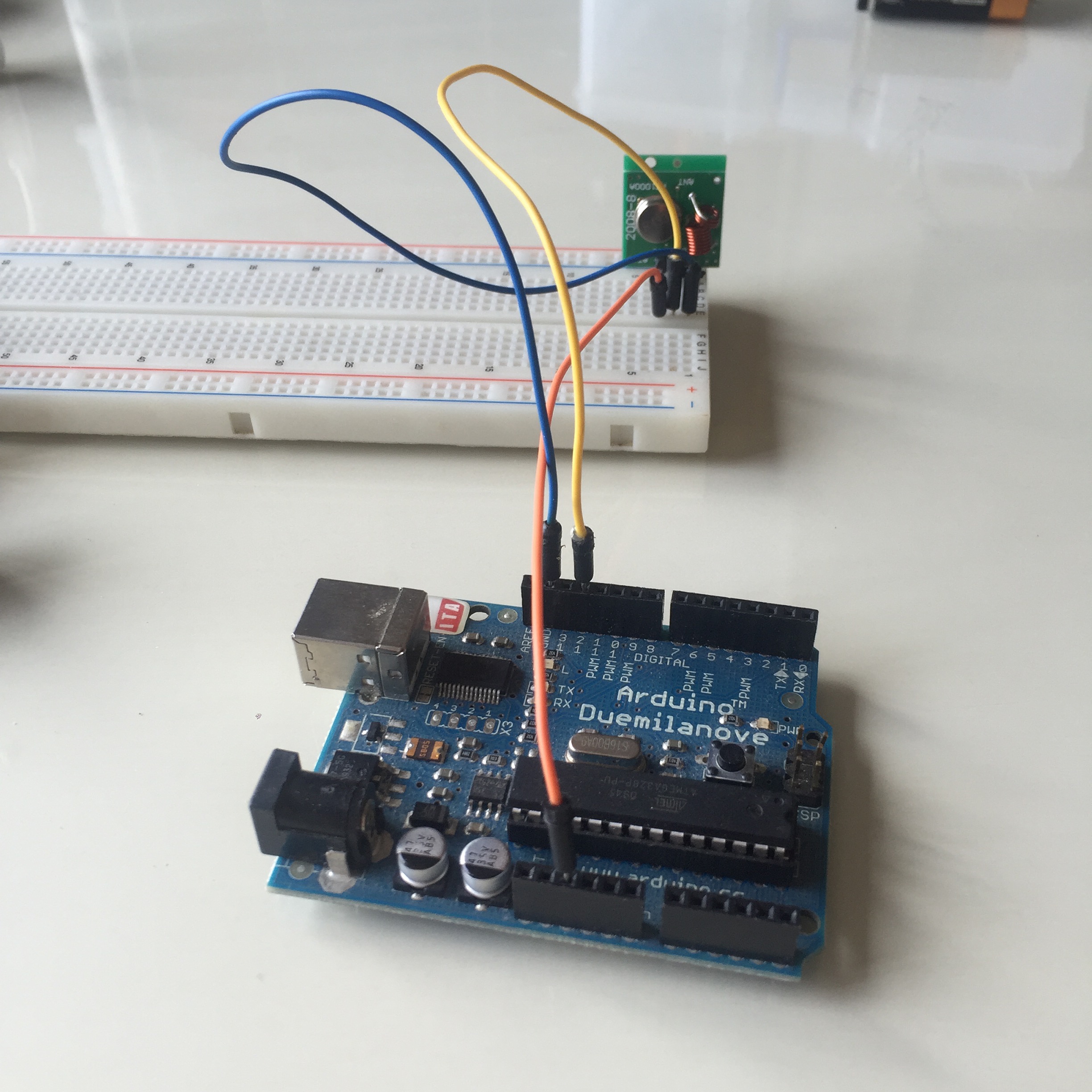
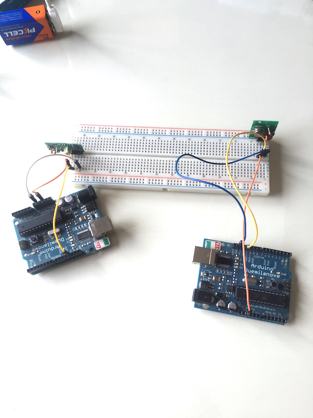
The connections follow the pic showed above :
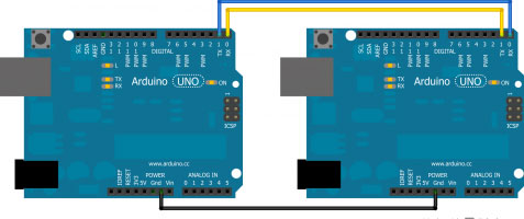
As you can see at Arduino References, i have to connect TX with RX and RX with TX : The "master" should write over Serial the desired value and the "slave" will be reads it and something happens!. This is the first idea...
I had to remember the AtMega 168 pinout correspondance with Arduino to identify the RX/TX pins. RX must be connected with TX in the other board and TX to RX as well.
Here began my problems described at WEEK PROBLEMS SECTION and HOW I SOLVED.
Our instructor always correct our designs before mill so he know our future problems later and when went with him for explain my problems, he learned to about how my mistake miss all the micro-processor logic because i forgot the DTR trace and now is not connect to nothing so he suggested to me focuss in my final project and design a board which i shuold use later.
1ST ATTEMPT
For practice the first concept about serial communications, i decided to follow the arduino reference at their Official Website and was researching in other students assignments for have new conclusions and understand better the things to do.
After i had clear my RX and TX pin at my boards i decided to connect boths following the correspondance learned from datasheet read :

For serial communication, i need the SoftwareSerial Library installed at my Arduino IDE, so here are the references followed :
The Arduino hardware has built-in support for serial communication on pins 0 and 1 (which also goes to the computer via the USB connection). The native serial support happens via a piece of hardware (built into the chip) called a UART. This hardware allows the Atmega chip to receive serial communication even while working on other tasks, as long as there room in the 64 byte serial buffer.
The SoftwareSerial library has been developed to allow serial communication on other digital pins of the Arduino, using software to replicate the functionality (hence the name "SoftwareSerial"). It is possible to have multiple software serial ports with speeds up to 115200 bps. A parameter enables inverted signaling for devices which require that protocol.
The version of SoftwareSerial included in 1.0 and later is based on the NewSoftSerial library by Mikal Hart.
The SoftwareSerial Library has been developed to allow serial communication to take place on the other digital pins of your boards, using software to replicate the functionality of the hardwired RX and TX lines. This can be extremely helpful when the need arises to communicate with two serial enabled devices, or to talk with just one device while leaving the main serial port open for debugging purpose.
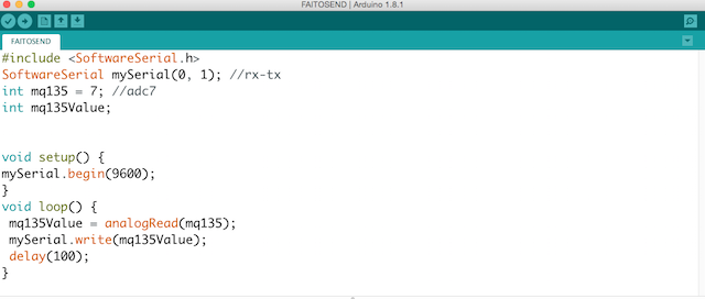
My Co2 Sensor Board was giving me a short noisy range of values. Then, for test if the Serial Communication is working properly, I hand-shacked the values to send over serial between the two boards.
In the example at his refrence web page, digital pins 10 and 11 on your Arduino or Genuino boards are used as virtual RX and TX serial lines. The virtual RX pin is set up to listen for anything coming in on via the main serial line, and to then echo that data out the virtual TX line. Conversely, anything received on the virtual RX is sent out over the hardware TX.
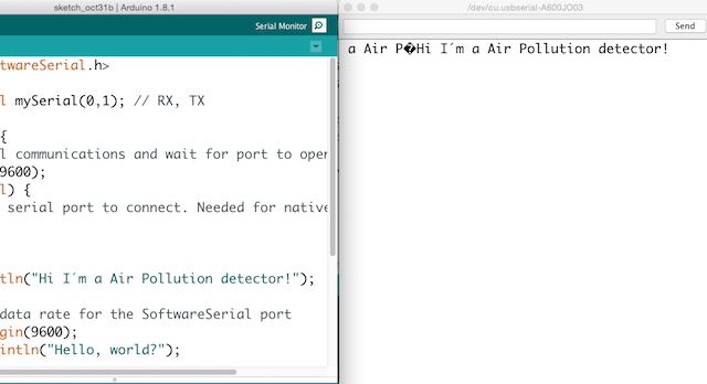
My boards are using 0 and 1 for RX and TX so i modiffied the example for have appropiate pins to this numbers, the other thing i made was change the baudrate to 9600 and add a custom message for know that my sensor is living.
First i made a test for blink the mosi led
Networking: Master Test I from Pilu Caballero on Vimeo.
2. I modiffied the Software serial example for practice the monitor serial communication :
/*
 Software serial multiple serial test

 Receives from the hardware serial, sends to software serial.
 Receives from software serial, sends to hardware serial.

 The circuit:
 * RX is digital pin 0 (connect to TX of other device)
 * TX is digital pin 1 (connect to RX of other device)

 created back in the mists of time
 modified 25 May 2012
 by Tom Igoe
 based on Mikal Hart's example

 This example code is in the public domain.

 */

#include

SoftwareSerial mySerial(0,1); // RX, TX

void setup() {
// Open serial communications and wait for port to open:
Serial.begin(9600);
while (!Serial) {
; // wait for serial port to connect. Needed for native USB port only
  }


  Serial.println("Hi I´m a Air Pollution detector!");

  // set the data rate for the SoftwareSerial port
  mySerial.begin(9600);
  mySerial.println("Hello, world?");
}

void loop() { // run over and over
  if (mySerial.available()) {
    Serial.write(mySerial.read());
  }
  if (Serial.available()) {
    mySerial.write(Serial.read());
  }
}
2nd ATTEMPT
Here are some references programs which o adapted for use with my boards.
void setup() {
  // initialize
  Serial.begin(9600);
}

void loop() {
  Serial.print('0');
  delay(100);
  Serial.print('1');
  delay(100);

}
// Arduino read data from serial from another Arduino

const int ledPin =  11;      // the number of the LED pin where i attached my led MOSI

char data;

void setup() {
  // initialize
  pinMode(ledPin, OUTPUT);
  Serial.begin(9600);
}

void loop() {
  data = Serial.read();

  if (data == '1') {
    digitalWrite(ledPin, HIGH);
    // Debug if the data check works
    Serial.print("ok");
} else {
 digitalWrite(ledPin, LOW);
  }
  delay(100);
}
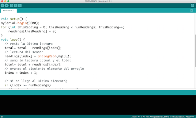
I wrote this program for test the Master Board with the sensor with the idea to approximate to the final idea
float MQ 135 = 7;
int gas = 0;
int valgas = 0;
int LED = 11;
void setup () {
  Serial.begin (9600);
  pinMode (LED, OUTPUT);
  //digitalWrite (LED, 0);
}

void loop () {
  // We read the gas data, and behave accordingly
  valgas = analogRead(MQ 135);
  Serial.println(valgas);

  if (valgas <= 200){
      digitalWrite (LED, LOW);
      delay (1000);
    }
    else if (valgas > 200) {

     digitalWrite (LED, HIGH);
     delay (1000);
   }
}
void valgas () {
  gas = analogRead (MQ 135);
  Serial.println (PollutionRisk);
}
Networking: Master Test I from Pilu Caballero on Vimeo.
The idea is use my computer as a Master, so i must to connect my boards in serie so TX from my Input board must to be connected to the TX from my Output Board. The first Slave will be coonnect to the computer trought RX.
So here is the program for the first Slave :
int led = 11;

char activar = 0;
char name = '1';
int Tx = 1;

void setup () {

pinMode (led, OUTPUT);
Serial.begin (9600);

}

void loop () {

digitalWrite (Tx, LOW); // Tx in tristate
pinMode (Tx, OUTPUT);

 if (Serial.available ()) {
    activar = Serial.read ();
    Serial.println (activar);

  if (activar == name) {
  pinMode (Tx, OUTPUT);
  digitalWrite (led,HIGH);
  Serial.print ("nodo 1");
  delay (1000);
  digitalWrite (led,LOW);
    }
   else {
   digitalWrite (Tx, LOW);
   }
    }
     }
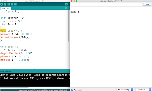
int led = 11;

char activar = 0;
char name = '2';
int Tx = 1;

void setup () {
pinMode (led, OUTPUT);
Serial.begin (9600);
}

void loop () {
  // Tx in tristate
digitalWrite (Tx, LOW);
pinMode (Tx, OUTPUT);
pinMode (Tx, INPUT);


 if (Serial.available ()) {
 activar = Serial.read ();
    Serial.println (activar);
    if (activar == name) {
    pinMode (Tx, OUTPUT);
    digitalWrite (led,HIGH);
    Serial.println ("nodo 2");
    delay (1000);

  digitalWrite (led,LOW);
    }
    else{digitalWrite (Tx, LOW);}
}
 }
For finnish i connected both boards : RX to RX and TX to TX and GND to GND and VCC to VCC and the NODE 1 (The CO2 board ) to the computer trying to send message from monitor and see how them is ocmmunicates :
I have a problem designing my slave board, i forgot the DTR pin so as my instructor learned to me, i miss all the logic of the board so she suggested me, focuss in my final project and design a possible final board. So the rest of teh assignment i finished with this board.
As i never made something similar, all the assignment learned me a lot and now i can connect more than 3 processors using my terminal as a master.
During 2018, mi remote instructor Luis Carvao suggested to me the idea to complete the assignment with something usefull for my final project so he proposed to me a challenge that of course i can´t to decline so i bought a pair of trasnmitter and receivers with the idea to make a Wireles Communication with this popular modules :
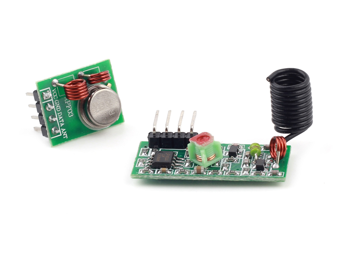
The first reference i followed was trought "Seed Studio Oficial Wiki website" where they described their products :
For learn about them i was reading the things founded there but it not was much information:
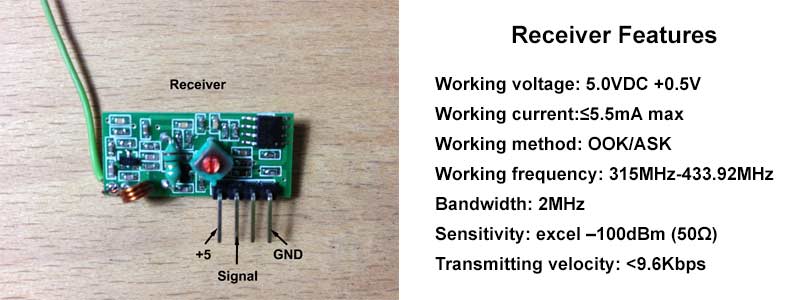
SPECIFICATION
Frequency: 433Mhz.
Modulation: ASK
Receiver Data Output: High - ½ Vcc, Low - 0.7v
Transmitter Input Voltage: 3-12V (high voltage = more transmitting power)
Receiver Input Voltage : 3.3-6V (high voltage = more receiving power)
DEMOSTRATION SCHEME
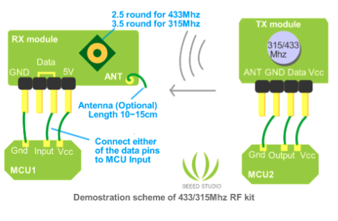
So i founded another information more helpfull for learn things such as radio communications between two AVR microcontrollers can be easy when specialized modules are used.
Transmitter and receiver modules are tuned to work correctly at 433.92MHz. Transmitter can be powered from 3 to 12V power supply while receiver accepts 5V. 5V is common for AVR microcontrollers so no problems with interfacing.
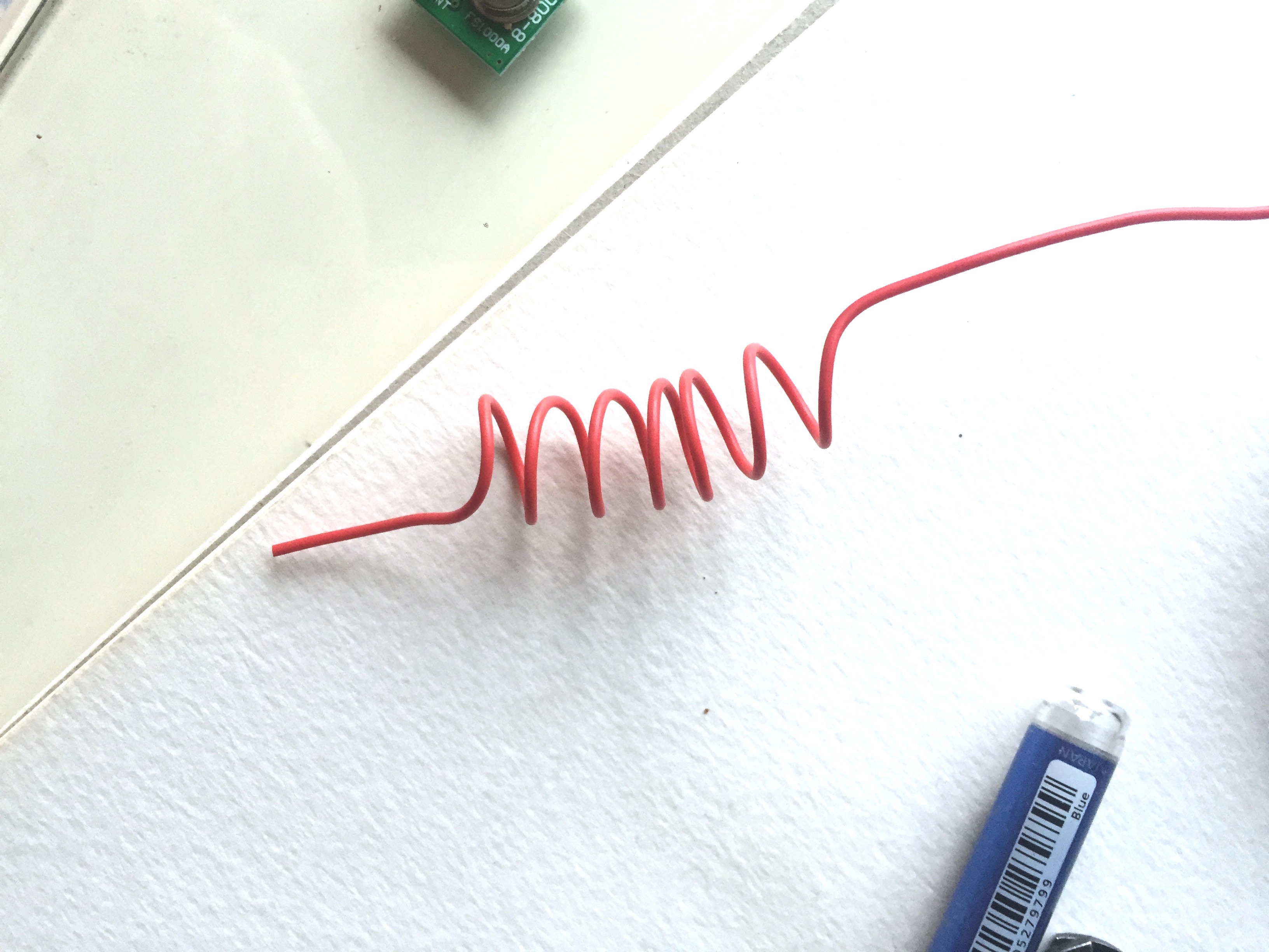
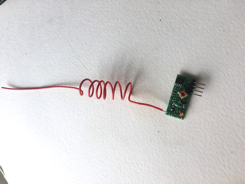
Modules don't require addition components, just apply power and connect single data line to send information to/from and that's it. For better distances apply 30 – 35cm antennas. Modules use Amplitude-Shift Keying(ASK) modulation method and uses 1MHz bandwidth.
Radio transmission is a bit more complicated than wired communications because you never know what radio signals are present on air. So all matters how transmitted signal is encoded.
Two considerations which will expand the range and efficiency of these two devices. First of all, each transmitter device has ansupply voltage range of 2 – 12 volts. The higher the voltage, the stronger the signal strength. Commonly, the microcontrollers run at 5 volts, so must to do separate power, either from a non-voltage resisted incoming voltage, or a separate power supply sharing a common ground.
These devices take very little amperage, consider using a 12 volt power supply, and running voltage directly from it to the transmitter, while isolating the other circuitry's voltage through a voltage regulator.
I learned that this devices can to work very reliably when are close to each other on a table but when they are separated they were able to communicate, but approximately 20% of messages were corrupted.
.These modules can work well for low performance, non-critical applications. For more demanding applications, more sophisticated (and more expensive) RF modules should be considered.
TRANSMITTER FEATURES
![]()
RECEIVER FEATURES
WIRING
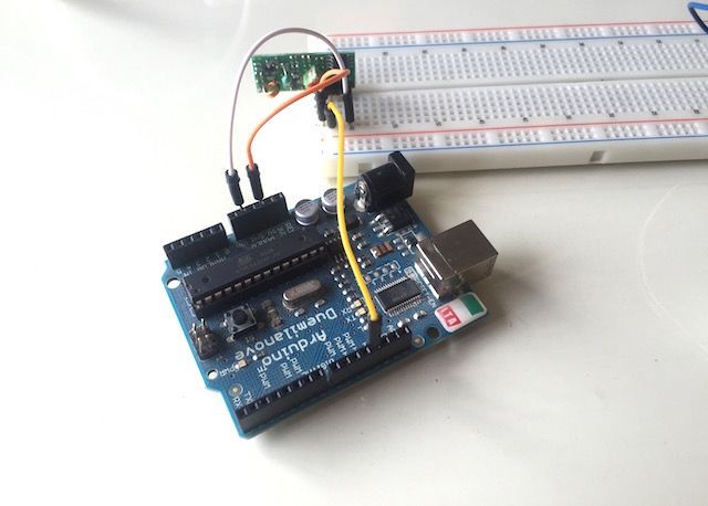
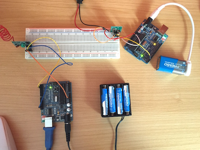
So first i made was conected both to 2 microcontrollers as arduino with the idea to implemented them later on my final project boards powering them with to 9V supply batteries :

EMBBEDED PROGRAMMING
For programm the modules with arduino, i must to install some libraries first :
VIRTUAL WIRE LIBRARY
VirtualWire is an Arduino library created by Mike McCauleythat provides features to send short messages, without addressing, retransmit or acknowledgment, a bit like UDP over wireless, using ASK (amplitude shift keying).
Does not use the Arduino UART. Messages are sent with a training preamble, message length and checksum. Messages are sent with 4-to-6 bit encoding for good DC balance, and a CRC checksum for message integrity.
Why not just use the Arduino UART connected directly to the transmitter/receiver? :
" ASK receivers require a burst of training pulses to synchronize the transmitter and receiver, and also requires good balance between 0s and 1s in the message stream in order to maintain the DC balance of the message."
I downloaded it from here : Virtual library
LEARNING TROUGHT FUNCTIONS LIBRARY
#include < VirtualWire.h To select the Transmitter Data Pin , void :
vw_set_tx_pinTo select the Receiver Data Pin , void :
vw_set_rx_pinSetup the speed of transmission , The speed of Tx must be as same as On Rx .The speed will be a Number of Bit Per Second between 0-9600 , for short distance you can use fast speed , For long distance "Up to 90m" you must use lower transmission speed as much as possible :
vw_setup(uint16_t speed);Start the receiver PLL running ,You must do this before you can receive any messages :
vw_rx_start();You must do this before you can receive any messages. When a messageis available (good checksum or not), vw_have_message() will return true :
vw_rx_stop();Block and wait until the transmitter is idle,called :
vw_wait_tx();Block and wait until a message is available from the receiver, call :
vw_wait_rx();Send a message with the given length, call :
vw_send(uint8_t* buf, uint8_t len);Returns true if an unread message is available from the receiver.,call :
vw_have_message();So i decided to use the reference programm modified by me for the transmitter with the idea to send a character as a number 1 and after 3 seconds will to send a 0 and then will to start the transmission.
//simple Tx on pin 12
//Written By : Mohannad Rawashdeh Modified by Pilar Caballero
#include < VirtualWire.h
char *controller;

void setup() {
pinMode(13,OUTPUT);
vw_set_ptt_inverted(true); //
vw_set_tx_pin(12);
vw_setup(4000);// speed of data transfer Kbps
}

void loop(){
controller="1" ;
vw_send((uint8_t *)controller, strlen(controller));
vw_wait_tx(); // Wait until the whole message is gone
digitalWrite(13,1);
delay(3000);
controller="0" ;
vw_send((uint8_t *)controller, strlen(controller));
vw_wait_tx(); // Wait until the whole message is gone
digitalWrite(13,0);
delay(3000);

}
In this is the code for the Receiver :
//simple Tx on pin D12

//..................................
#include < VirtualWire.h
void setup(){
vw_set_ptt_inverted(true); // Required for DR3100
vw_set_rx_pin(12);
vw_setup(4000); // Bits per sec
pinMode(13, OUTPUT);

vw_rx_start(); // Start the receiver PLL running
}

void loop(){
uint8_t buf[VW_MAX_MESSAGE_LEN];
uint8_t buflen = VW_MAX_MESSAGE_LEN;

if (vw_get_message(buf, &buflen)) {
if(buf[0]=='1'){
digitalWrite(13,1);
}
if(buf[0]=='0'){
digitalWrite(13,0);
}
 }
  }
Hello World Transmitter Exercise :
![]()
Message Transmitter Program:
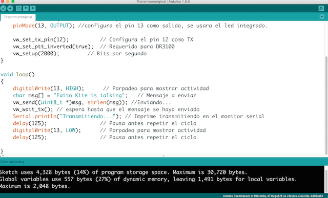
#include VirtualWire.hvoid setup(){ Serial.begin(9600); // abre el puerto de serie Serial.println("Transmisor listo"); // Imprime "listo" en el monitor serial pinMode(13, OUTPUT); //configura el pin 13 como salida, se usara el led integrado. vw_set_tx_pin(12); // Configura el pin 12 como TX vw_set_ptt_inverted(true); // Requerido para DR3100 vw_setup(2000); // Bits por segundo } void loop(){ digitalWrite(13, HIGH); // Parpadeo para mostrar actividad char msg[] = "Faito Kite is talking"; // Mensaje a enviar vw_send((uint8_t *)msg, strlen(msg)); //Enviando... vw_wait_tx(); // espera hasta que el mensaje se haya enviado Serial.println("Transmitiendo..."); // Imprime transmitiendo en el monitor serial delay(125); // Pausa antes repetir el ciclo digitalWrite(13, LOW); // Parpadeo para mostrar actividad delay(125); // Pausa antes repetir el ciclo }
Receiver Program:
![]()
#include VirtualWire.hint count; void setup(){ Serial.begin(9600); // abre el puerto de serie Serial.println("Receptor listo"); //Imprime "listo" en el monitor serial pinMode(13, OUTPUT); //configura el pin 13 como salida, se usara el led integrado. vw_set_rx_pin(12); //Configura el pin 12 como TX vw_set_ptt_inverted(true); //Requerido para DR3100 vw_setup(2000); // Bits por segundo vw_rx_start(); // Inciar el receptor } void loop(){ digitalWrite(13, HIGH); // Parpadeo para mostrar actividad //uint8_t buf[VW_MAX_MESSAGE_LEN] = {}; uint8_t buf[VW_MAX_MESSAGE_LEN]; //Almacenar en buffer los datos recibidos uint8_t buflen = VW_MAX_MESSAGE_LEN; //Determina el numero de caracteres recibidos if (vw_get_message(buf, &buflen)) {// Si hay un mensaje recibido ejecuta... int i; Serial.print("Rx: "); //imprime Rx en el monitor serial for (i = 0; i < buflen; i++) { //rutina para impresion del mensaje recibido char c = (buf[i]); // guarda el caracter recibido para despues imprimirlo Serial.print(c); //imprime el caracter recibido en el monitor serial Serial.print(""); //deja un espacio en el monitor serial } count++; //incrementa contador Serial.print(count); //imprime el contador en el monitor serial Serial.println(""); // salto de linea monitor serial } delay(125); // Pausa antes repetir el ciclo digitalWrite(13, LOW); // Parpadeo para mostrar actividad delay(125); // Pausa antes repetir el ciclo }
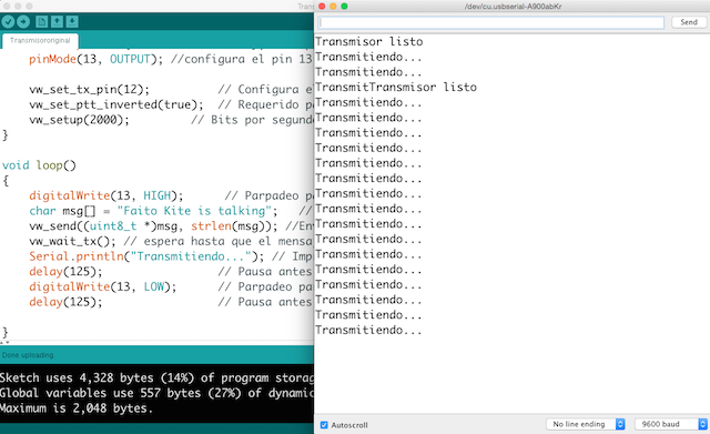
Results
After some attemps later i decided to change the speed of transmissions to 4000 bits per second but nothing happens.
![]()
![]()
WEEK FILES
MY FINAL PROJECT
Thinking in my final Project i begin with the CO2 Sensor Callibration explained in my
Final Project Process Page at Programming processes section.
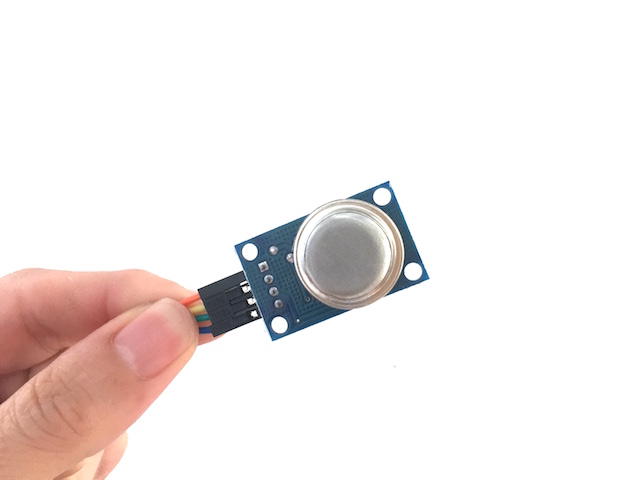
MY SENSOR:
References about Gas Sensors
I found at the Arduino Offical Web page some refrences about the use of this kind of sensors, there you can find basic overwiew with data sheets about the family but i decided copied to this page for never forget the basics things :
Introduction
The MQ series of gas sensors use a small heater inside with an electro-chemical sensor. They are sensitive for a range of gasses and are used indoors at room temperature.
They can be calibrated more or less (see the section about "Load-resistor" and "Burn-in") but a know concentration of the measured gas or gasses is needed for that.
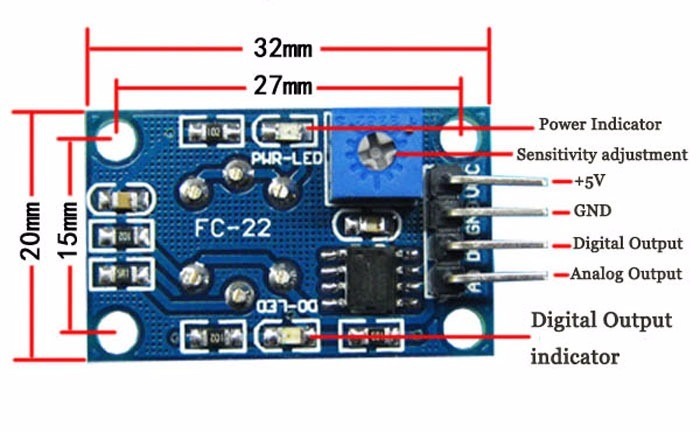
The output is an analog signal and can be read with an analog input of the board i designed.
Read the datasheet
Try to find a few datasheets for the sensor, and read them careful.
Since there are no electronic components inside, therefor most sensors can be used with AC and DC voltages.
Be careful when connecting it for the first time. If the pins are connected wrong, the sensor could get damaged, or it could be broken instantly. There are also shields available with these sensors pre-installed.
Wiring
The preferred wiring is to connect both 'A' pins together and both 'B' pins together. It is safer and it is assumed that is has more reliable output results. Although many schematics and datasheets show otherwise, you are advised to connect both 'A' pins together and connect both 'B' pins together.
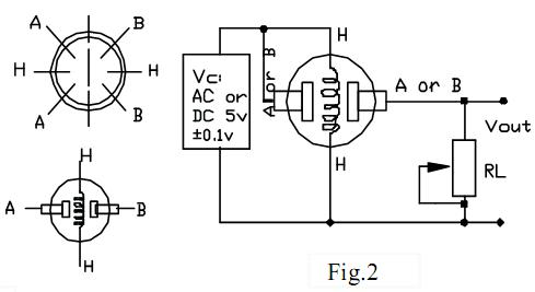
In the picture, the heater is for +5V and is connected to both 'A' pins. This is only possible if the heater needs a fixed +5V voltage.
The variable resistor in the picture is the load-resistor and it can be used to determine a good value. A fixed resistor for the load-resistor is used in most cases.
The Vout is connected to an analog input of the Board designed
The voltage for the internal heater is very important.
Some sensors use 5V for the heater, others need 2V. The 2V can be created with a PWM signal, using analogWrite() and a transistor or logic-level mosfet.
The heater may not be connected directly to an output-pin of the Arduino, since it uses too much current for that.
Some sensors need a few steps for the heater. This can be programmed with an analogWrite() function and delays. A transistor or logic-level mosfet should also in this situation be used for the heater.
If it is used in a battery operated device, a transistor or logic-level mosfet could also be used to switch the heater on and off.
The sensors that use 5V or 6V for the internal heater do get warm. They can easily get 50 or 60 degrees Celcius.
After the "burn-in time", the heater needs to be on for about 3 minutes (tested with MQ-2) before the readings become stable.
The sensor needs a load-resistor at the output to ground. It's value could be from 2kOhm to 47kOhm. The lower the value, the less sensitive. The higher the value, the less accurate for higher concentrations of gas.
If only one specific gas is measured, the load-resistor can be calibrated by applying a know concentration of that gas. If the sensor is used to measure any gas (like in a air quality detector) the load-resistor could be set for a value of about 1V output with clean air.
Choosing a good value for the load-resistor is only valid after the burn-in time.
Some datasheets use the term "preheat", but it is the time to burn-in the sensor. This is meant to make the sensor readings more consistent. A time of 12 or 24 hours is usually used for the burn-in time.
The Burn-in is achieved by applying normal power to the sensor (to the heater and with the 'A' and 'B' pins connected, and with a load-resistor). In some special cases a specific burn-in is needed. See the datasheet if the sensor needs such a specific burn-in.
Interesting links
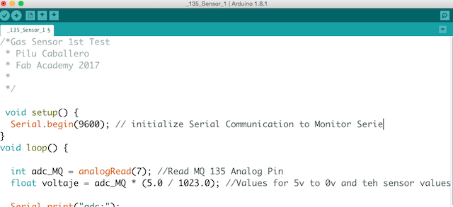
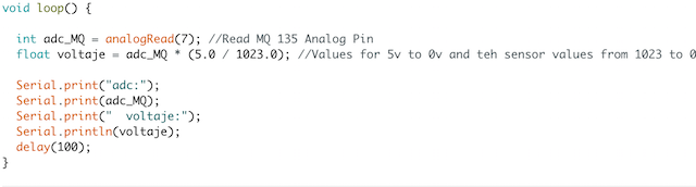
MQ135 : A Sensor For Air Quality
- The heater uses 5V.
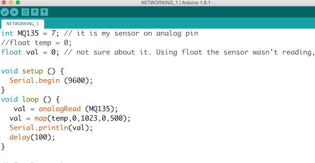
An example how to use it:
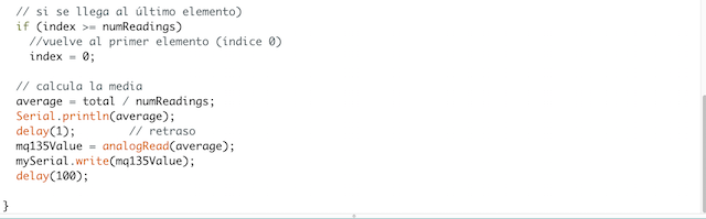
An example with calculation of the CO2 value:
Search for datasheet:

Networking: Master Test I from Pilu Caballero on Vimeo.
Faito v. 01 : High Bright Led Board from Pilu Caballero on Vimeo.
1TESTVOLTAGE_SERIAL from Pilu Caballero on Vimeo.
PROGRAMING INPUT DEVICES : TEST MQ135 WITH LITHIUM ION POWER SUPPLY from Pilu Caballero on Vimeo.
The processes for callibrated the sensors was a fight but finally i can detect some differents atmospherics gases. You can know more about this process in my Final Project Process Page :
OUTPUT DEVICES Receives information data from INPUT DEVICE blinking bright Leds described at Electronics section with mapped values from the analog sensor.
High Bright Leds from Pilu Caballero on Vimeo.
Testing Slave Board with a Bright Led from Pilu Caballero on Vimeo.
All the Files about this programs are at my :