Final Project Process
Index
- Research Process : Aerodinamics.
- Learning how to sew a Kite. References Followed
- Design Processes I: The Kite´s Design
- Design Processes II: The Connector. Diedro Generation.
- Design Processes III: The Start for the ROD.
- Design Processes IV: The Box for balse wood.
- The Patterns.
- Prototype Time I: Laser Testers.
- Prototype Time II: Building a Paper Kite
- Sewing Testers
- Sewing the 6 FACES.
- Assembled teh Kite for the first time.
- Wiring and Communications.
- 3D Printer Testers
- Electronics I : Learning about the Sensor Reading the Datasheet.
- Electronics II : Output Devices Testers
- Electronics III : The Power Supply.
- Programs: Basic Callibrations
- Programs: Callibration detailed.
- Questions Answered
- Files
- My Week Problems Solved
- Things I Learned
- My Week Conclusions
RESEARCH PROCESS
Design References :
FEBRUARY
Here are some references i studied for learn about the Kite´s World :
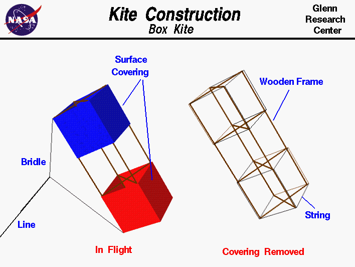
Kites depend on surfaces to generate the aerodynamic forces necessary for flight (an appropiate pattern design) and use rigid structures (fiber carbon tubes) to support the surfaces and transmit the forces (caps, connectors and rings). Different kites have different types of surfaces and structures; he left side of the figure shows the kite as it would appear in flight and the right side shows the inner structure.
Kite flying is a delicate balance between aerodynamic forces, the weight of the parts of the kite, and the distribution of these forces. In flight, the kite is connected to the flyer by the control line and the flyer can feel the tension in the line created by the aerodynamic forces on the kite.
The line is connected to the kite by a string bridle. The place where the bridle connects to the line is called the "bridle point and the kite pivots about this point in flight.
The bridle point can be adjusted to change the flight characteristics of the kite. The surfaces of the kite are covered by a thin covering of paper, plastic, or cloth, which deflects the wind downward and creates the aerodynamic forces of lift and drag on the kite.
If we remove the covering, we should to see the structure which transmits the aerodynamic forces to the bridle.
A kite structure is made from several sticks and some string. The sticks can be made of a light but strong piece of wood such as balsa or bamboo, or a light but strong plastic tube. In the box kite, there are four main "leg" pieces of equal length and four "cross" pieces which are made from two sticks. The structure is held together with strings wrapped around the legs at the location of the cross members.
The surface covering is attached to the strings. Notice that the structure is small, light and strong. It must be made strong to withstand the forces of the wind and weight, but it must also be light to keep the weight low. To save weight, only two "cross" pieces are used on some box kites. The trade of strength and weight must be considered in every flying thing from a kite to a large airliner.
Flying
While the forces on all kites are the same, each kite flies a little differently. Some kites are highly maneuverable and some kites are very stable. There are kites with multiple control lines that can perform stunts, while other kites can be flown to high altitudes. So we can use math techniques that you learn in school to determine the altitude of a kite graphically. With a little more knowledge of mathematics, you can actually calculate the altitude at which the kite is flying.
Regardless of the type of kite, the flyer must always fly safely for the protection of others, to protect property, and to insure that the kite can be flown again.
An excellent way to gain an understanding and a feel for aerodynamic forces is to fly a kite. Kite flying is fun when done safely and you can study many of the fundamentals of airplane aerodynamics because a kite works very much like an airplane. As with an airplane, there are some geometrical definitions which will simplify our studies of kite aerodynamics. Kites come a wide variety of shapes and sizes, but the definitions found on this page can be applied to most kites.
This page shows a three view diagram of a winged box kite. In a three view diagram, an object is shown from the front, side, and top with all three views drawn to the same scale. We use three view diagrams because some geometrical variables are easier to visualize in one view than in another.
Beginning with the Front View, we note that the surface area-A which is used in the calculation of lift and drag is the frontal projected area of all of the surfaces of the kite. You learn how to compute the area of various shaped objects in middle school. For this winged box kite, the frontal projected area includes the full area of both wings (colored yellow) and the projected area of the top and bottom boxes (colored green). Notice that this is a projected area, not a geometric area. If each panel of the box kite is a square, there are four panels on the top and four on the bottom to form the two boxes.
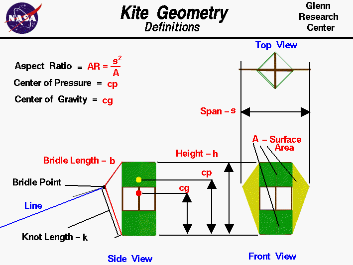
From the Top View, we see that each panel is inclined to the front at a 45 degree angle. Then the projected area Ap of each panel is equal to the geometric area Ag times the cosine cos of 45 degrees:
If the geometric area is slanted to the front then the frontal projected area is always less than the geomtric area. The top and front view also help us define the span-s of the kite. The span is the widest distance from side to side. It is the same as the wing span of an airplane, the distance from one wing tip to the other wing tip. The ratio of the square of the span to the area A is called the Aspect Ratio AR of the kite.
The procedure requires a flyer and an observer and a tool, like the one shown in the upper right portion of the figure, to measure angles. The observer are stationed some distance L from the flyer along a reference line. You can lay a string of known length along the ground between the observers to make this reference line. A long line produces more accurate results. To determine the kite's altitude, the flyer calls out "Take Data", and measures the angle a between the ground and the kite. This measurement is taken perpendicular to the ground. The flyer then measures the angle b between the kite and the reference line. This measurement is taken parallel to the ground and can be done by the observer facing the kite, holding position, and measuring from the direction the flyer is facing to the reference line on the ground. When the observer hears the call, "Take Data", the observer must face the kite and measure the angle d from the ground to the kite. The observer must then measure the angle c, parallel to the ground, between the direction the observer is facing and the reference line in the same manner as the flyer. Angles a and d are measured in a plane that is perpendicular to the ground while angles b and c are measured in a plane parallel to the ground.
With the four measured angles and the measured distance between the observers, we can use graph paper to build a scale model of the kite in flight and we can determine the altitude h of the actual kite. Scale models depend on the mathematical ideas of ratios and proportions which you learn in grade school. To determine the altitude, we first draw the reference line L on the graph paper. Make the length of the line on the graph paper some known ratio of the measured length. The length of the line on the graph paper sets the scale of the model. For instance, if the measured length was 100 feet, we might make the line on the graph paper 10 inches long. Then one inch on the graph paper equals 10 feet in the real world. Now draw two lines beginning at the ends of the reference line and inclined at the measured angles b and c.
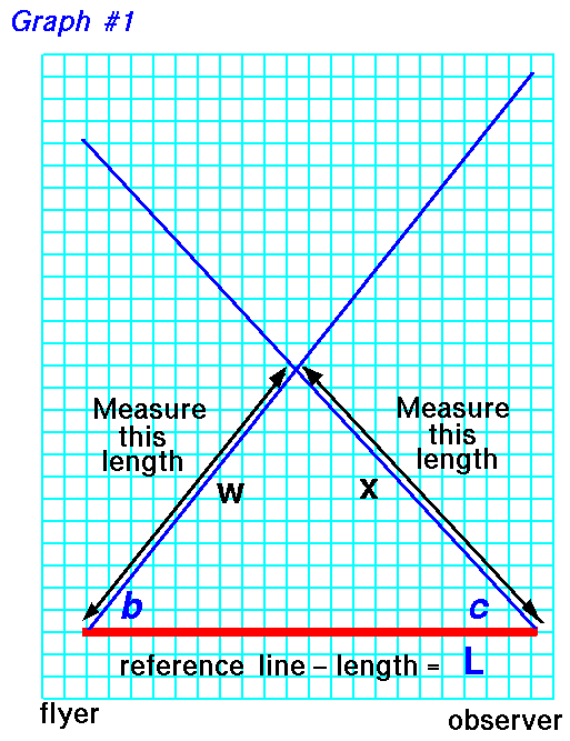
On the graph paper use a ruler to measure the distance w from the beginning of the reference line, near flyer, to the intersection of the two drawn lines. The intersection point marks the location on the ground that is directly beneath the flying kite. Also measure the distance x from the end of reference line, near the observer.
As discussed on the web page with the derivation of the equations, we really only need three measured angles and the reference length to accurately determine the altitude. So you can use either angle a measured by the flyer, or angle d measured by the observer, to determine the altitude. If you measure all four angles, you can make two estimates of the altitude h; they should be the same answer, but if they aren't, you can average them.
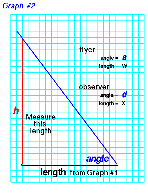
Now count the blocks, or measure the length, of the vertical line h. Convert this distance by the scale of the reference line, and you have determined the altitude h of the kite. If you use the measurments of the observer, substitute the length x for length w and angle d for angle a. For instance, in our example, 1 inch equals 10 feet. If your measured height h is 10 inches, the kite was flying 100 feet in the air. If you understand the mathematical ideas of trigonometry you can also calculate the altitude of the kite and check your graphical solution.
Also i studied more theories and here are all my notes and conclusions which LEARNED TO ME HOW FLIGHTS THE KITES, WHY, WHEN, MEASURES...


Sewing Machine thoughts:
If you are new to sewing, you don't have to buy a new sewing machine. In fact, don't buy a machine at all. Find one for free. Pick one off the curb on trash day. Tell everyone you know that you want to learn to sew kites and someone will feel so sorry for you that they will give you a machine. Sewing machines are like fitness equipment. Many of them are bought brand new with the best of intentions, then stuck in a closet and never used. Find one of those machines that has spent its entire life in a closet and make it your own.
- Older is generally better, WHY?
-Metal body and gears, stronger motor and belts.
-Easy to clean and maintain.
-Simple, all gear and cam driven. No step motors.
-You don't need 1,000 different stitches. You will only ever use four. Okay, so 'four' is a number I picked out of thin air.
-Vertical bobbin, not a flat drop-in.(Vertical bobbins are easier to adjust than flat drop-ins.)
-Ability to stop Needle up / Needle down.
- Some electronic machines have a button to push which makes the needle always stop in the 'down' position, into the fabric. This is very handy when sewing appliqué. Pushing the button again makes the needle always stop in the 'up' position. This makes it easy to remove work and trim threads without having to move the handwheel to bring the needle to proper position first.
-Very wide zig-zag. Most will do 5 mm. Look for 5.5 to 6 mm.
- Variable width zig-zag.
-A 3-step or Triple zig-zag.
A 'Bobbin-out' warning. (Some machines have a warning light that comes on when there are only 3 yards of thread left on the bobbin.) Dual Feed. (This is sometimes erroneously called a Walking Foot. It isn't a walking foot by sewing industry standards, but it is a very positive feed feature. It really helps when sewing ripstop nylon.)
Tension:
Proper tension, top and bottom, is crucial to good sewing machine performance. Most sewing 'problems' can be traced to tension or needle problems.
Sewing kites involves sewing ripstop kite fabric that is thin and slippery. 'Normal' thread tensions will tend to pucker up the fabric. Kite sewing usually involves much lower tension, both top and bottom.
Setting Top Tension
With Bobbin in machine, sew a row of stitches on a piece of scrap.
Set/check tension on same type material you intend to sew.
If bottom stitches are being pulled UP, lower top tension.
If top stitches are being pulled down, increase top tension.
If stitches are even, no bumps top or bottom, no puckers in cloth, good to go.
If fabric is puckering, remove Bobbin, lower bottom tension, and start over.
Very big loops of very loose thread on bottom means no top tension. Check the thread path again. Make sure the thread is between the disks and under the spring on older machines. Make sure the thread is to the left of the pressure plate on newer machines.
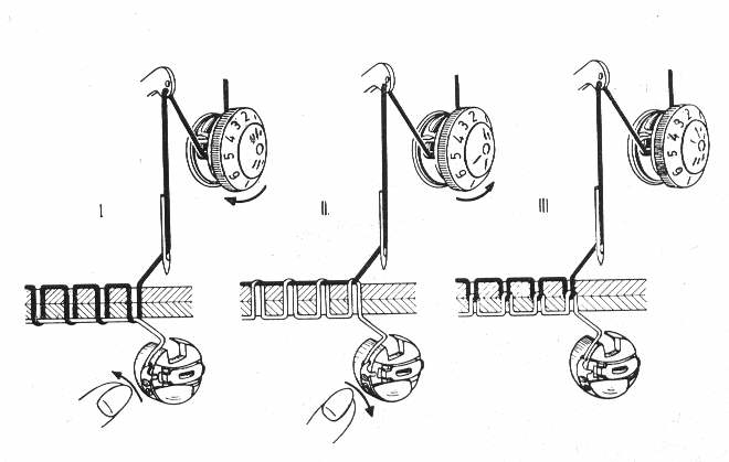
In the illustration above, (I) the bottom tension is tighter than the top. (II) shows top tension tighter than bottom, (III) shows ideal tension with both threads meeting in the middle. Using two different colored threads of equal thickness makes it easier to see the differences for adjustment.
Needle: It is tempting to think of the needle as simply poking the thread through the fabric to sew. That is only a small part of the picture. Think of the needle as a delivery system to get the top thread to the bobbin race so the rest of the sewing machine can complete the stitch. The thickness of the thread, the groove in the side of the needle, the scarf on the back of the needle, the size of the eye of the needle, and the size of the hole the needle makes on the fabric all contribute to how well the actual stitch comes out.
Needle and thread note: How many times would you guess that one section of top thread passes thru the eye of the needle? Once? Twice maybe? Would you believe that using HB-33 thread at 8 stitches to the inch (3 mm), one section of thread passes back and forth thru the eye of the needle 24 times? Actually, that is 24 round trips, which means 48 passes through the eye. Think of that when choosing needles and thread. Small needles with small eyes trying to sew lumpy thread often have tension problems.
Size matters :
- Too small a needle invites tension problems.
-Some people say that too big can excessively damage the fabric (** see note in Thread section)
- Best to use is a #14, 90 European, Regular Point.
- We can make a good case for using 16's and 18's too.
Position matters:
-Make note of where the 'flat' is before you take it out.
-Put it back in the same way it came out.
- Make sure it is all the way in.
-If you didn't look at the way it came out, there is a one-in-four chance of putting it in right.
Brand matters :
Use the brand of needle that came with the machine, the brand the Manual recommends. There is a relief, a scarf, a 'gouge' on one side of the needle that makes it possible for the bobbin race hook to grab the thread. The shape of this scarf is different on different brands of needles. Different brands of machines require different brands of needles.
Don't sew with a bent or dull needle.
Dull needles make a 'snap' noise in the fabric.
Bent needles will drop stitches, especially in zig-zag.
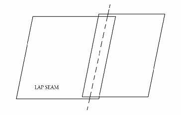
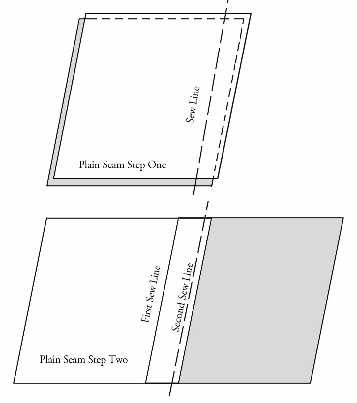
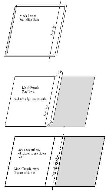
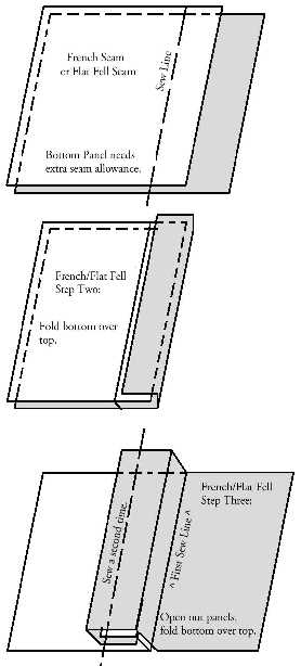
LEARNING LAPS, MOCKS, FRENCH SEAMS AND ALLOWANCES
<
NAMING
NAMING
Faito v.01 :Called in honor to my best doggy died during the MTM Assignment.
Logo based in 2D Kite Design
DESIGN PROCESS
THE FINAL IDEA
The Kite made at the 2nd week : As i mentioned several times my 1st idea was made a 6FACES Kite but during the project development i learned that my first design for fly in Madrid´s wind conditions with the weight of the electronics is not possible, so i decided simply all the system. Here you can see the first design with TinkerCad :


Here you can see more about the designs made and the experience during my first days:
4 FACES (Atlantic version) :

This MONTH is for design, so i decided to begin with Faito v.01 6 FACES . For this i used AutoCad, i was learning from tutorials and after 15 weeks and my training with different softwares was a great experience.


FAITO v.1


SIMULATIONS WITH WIND FORCES
Faito v.02_4 FACES (Atlántic version) Cinema 4D:
Faito v 1.0 : Simulation test I from Pilu Caballero on Vimeo.
Faito v.1.0 : Simulation test II from Pilu Caballero on Vimeo.
Faito v 1.0 : Simulation test I from Pilu Caballero on Vimeo.
Faito v.1.0 : Simulation test II from Pilu Caballero on Vimeo.
MECHANISMS : CARBON TUBES CONNECTORS

I Visited the local store for get references and measures :


MAIN END CAPS
1st ATTEMPT : I designed the first one with AutoCad :
My Kite have 2 types of end connectors : I print at "3D Printer and Scanning Week" some experimental parts designed with OpenScad for test Reality vs Virtual . See my Week Page Assignment here :


Also, in
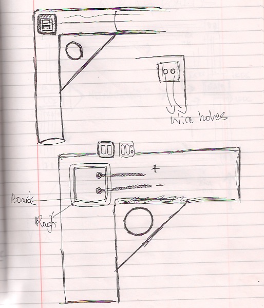
i was thinking about the assembled and decided made an exercise. The Final purpose for this design was learned how to hide wires and how to assembled the main electronics boards for the Kite, the CO2 input board and the ledsBoard for output explained at Electronics section.


MY OWN DIEDROS : The Diedro Generation
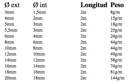
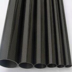
This an important piece because it made the tubes for flexibles, so here are some references to consider at the design :

My sketch thinking in hide wires:


CAPS FOR RODS
For the ROD design i decided to use OpenScad, a software which i was practicing a lot during the fabAcademy:
Here are some pics about the process and the results of my models readies for print at the 3D Printer.
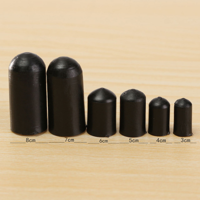


Here is the design for 8 mm Carbon Fiber Tubes
Also i made one for the prototype thinking in our Replicator tolerances :
Faito v.02_4 FACES (Atlántic version) Cinema 4D:
I have for the Atlantic version, an study about "diedro connectors> that actually call "The Diedro Generation" a process for learn how to design one which can to work with high wind forces and as i mentioned to Neil at my presentation for made the electronics soft at the future and assembled the wires properly with conductive thread:
THE BOX FOR MQ135 SENSOR
1st ATTEMPT : I designed the first one with AutoCad :


 >
>
THE PATTERNS
I never design a parametric patterns for fabrics before, never designed a "Kite" so i decided made a Geometrical Design and began with the idea to design a 6 Faces and Parametrical Kite. Unfortunely to find references for this kind of kites was really difficult so i had to began from the images mentioned at my Final Project Proposal :
Here a sketch with measures estimated at the first moment:

As you can see i hadn´t idea about the design and after 20 weeks this make me laugh a lot....


1st ATTEMPT:
6 FACES at FUSION 360ºi made this with the idea to begin to learn how to sew the Kite:


4 FACES at Fusion 360º for prototype :


Finally used Antimony for made the Final Design and export such as .png and vectorizing it at Inkscape .
This Design involve the use of Laser Machine Technology so i had to make some test explained later. As you can see i decided to simply my project for different factors :


As i observed, when exported the design, i lost a square so decided made other attend.
3rd ATTEMPT AND FINAL :
After my studies about the weights and forces of the wind, i decided to redesign the patterns for 6 FACES, opening the main squares for made the kite more light :


You can find all Final Patterns for my 6 and 4Faces Parametric Kite at my Final Project Page below:
PROTOTYPE PROCESS
During this processes i was prototyping differents things in relation with fabrics, tension , sewing and of course electronics and code.
The Process learned me a lot things which i never practice before and i can to practice others learned during the Fab Academy Diploma. So in relation with technolgies used, i describe the workflow followed :
FABRICS
LASER TESTERS
The use of Laser Machine is an essential for fabricate and build the Kite. This testers was for practice the cut of my fabrics.The laser technology made the patterns stables for sew later. The material for build the Kite is Nylon Ripstop about 42 grms. Special Fabrics for make Kites. Process made : Designed little pieces with fusion 360º , exported as .dxf, as AutoCad (2014) as our Laser detect without problems :


As i never cut this kind of fabrics before i made some bit tester, trying differents settings to configure the perfect for cut my real patterns later.
| POWER | SPEED | CORNER POWER |
|---|---|---|
| 60 | 20 | 12 |
| 80 | 16 | 14 |
| 70 | 14 | 11 |
| 40 | 18 | 16 |
BULDING A PAPER KITE SCALE TO 1:300
In April i went to my city and there meet the FabLab Sevilla
and decided to build the first prototype. During this process i cutted a first pattern for visualize the final design and and lear how to sew it :


After this practice i begin to feel excited, the kite is not more in my mind, i have something!! ;)
SEWING TESTERS - SEWING A MINI KITE SCALE TO 1:300
HOW TO INSERT THE BOBBIN AT THE MACHINE
A long time without sew nothing so i decided to visit my friend Bela and his atellier : "Creado en Sevilla" a nice place close to of our primary school and there refreshed the basics :
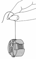
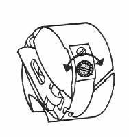
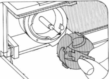


THIS LEARNED TO ME HOW TO DESIGN THE KITE CORRECTLY
But the most important thing, this task, made me to redesign the patterns thinking in how i should to assemble it. I was thinking in trianles always, but the design involve to sew squares. From here began the real patterns design.

As never Sew Nylon Ripstop before i decided to make some testers with stitches for adjust my sewing machine, refresh sewing techniques and getting new conclusions.
1. First i did was Stitches testers with the aim to use 2 types:
Sewing Tester: Zig-Zag Stitches for Nylon Ripstop 42 grms. Faito v.1 : A Kite for Practice the Enviromental Respect. from Pilu Caballero on Vimeo.
a) Zig Zag For tabs and Reforces
b) Single line for 4 Squares Sew.
Here was the process :


THIS LEARNED TO ME HOW MUCH TIME I WILL TO SPEND SEWING THE KITE AND HOW MUCH DIFFICULT IS
SEWING THE 6 FACES : PROTOTYPING TABS AND HEMS
Thinking in time i decided to sew the 6 FACES for prototype and begin with the flights. First of all i went to locals vendors where learn a lot things too about mechanisms, how to sew, how and when apply the material and bought Nylon Ripstop in White.
Daniela and his boss show me another kites models and advise in every i asked them.


With my fabrics cutted i begin with the union of big squares with a simple stich (i deciced use this one for all because is a prototype, but the ideal is use Zig - Zag for reforces) :
I spent 26 hours in the fabrication but when i finished i´m really happy with the results and decided add the rest of mechanisms such as the rings and some commercial connectors.


As i mentioned, the fiber carbon tubes must to be cutted too so i used my Dremmel from my grandFa but before a put my safe glasses and gloves:
The rest of the materials are gifted as a surprise by a good friend who work in the place where more wind in Spain, Tarifa. He is following my academy pics at instagram so he decided call me and ask about the project. When explained the idea, he thought in the costs and BOM, of course, my idea is a expensive project, so for prototype i must to reduce this BOM and save money for the real.
When a packet from his company
OZU-Tarifa
arrived to my home i was crying for a time. My Kite have the name of my dog, he born in Cádiz and my friend loved him a lot. Is a lovely act. Thanks Elias!1. Anchoring or stabilizing seams before sewing, holding the panels together:
2.
3. Hems: Edge treatments / edge binding / bias tape / grosgrain tape
THIS LEARNED TO ME HOW TO ADD THE SPINAKER

ASSEMBLED
For this process and with the idea to obtein a feedback from my kids and think about the assembled guide, i decided to bring the prototype to the Maxwell School where they learned me how to make my future workshops.


THIS LEARNED TO ME HOW TO GET FUN WITH THE PROJECT AND THINK IN WIRE ASSEMBLED

WIRED
Other important thing is hide the wires so i was thinking in this :


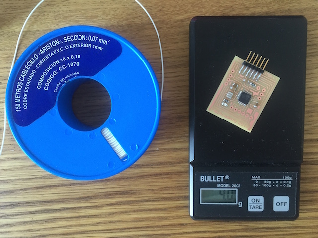
WEIGHT : Main Question for Resolve


FLIGHT TESTERS
Waiting for the wind : I decided to install an APP called Windy
for study the wind previsions in Madrid for the rest of the month so this task learned to me how to intrepeter the pictograms there.3D PRINTER TESTERS
The main 3D designs for print are the L CONNECTORS and the CAPS for ROD : This pieces was designed at Cinema 4D and OpenScad so was necessary to check the mesh quality, because as my instructor advice me, this software may be loose things when object is exported. But after i check looks all are well.
1st ATTEMPT
As i have a Prusa, i decided to print some tester before try my designs with the printers at our fablab. For prepare the files before send to the printer, i used CURA :
1. Settings for the 8 mm Rod Cap :


2. Settings for the Sensor Cap :


3. Settings for the Diedro I :
2nd ATTEMPT
This happen if you don´t scale correctly a piece at Cinema :

The last design was addapted for print at the Maker Bot which usually use at the CEU FABLAB.
ELECTRONICS PROCESS
MY SENSOR:
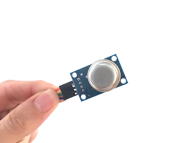
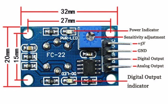
References about Gas Sensors
I found at the Arduino Offical Web page some refrences about the use of this kind of sensors, there you can find basic overwiew with data sheets about the family but i decided copied to this page for never forget the basics things :
Introduction
The MQ series of gas sensors use a small heater inside with an electro-chemical sensor. They are sensitive for a range of gasses and are used indoors at room temperature.
They can be calibrated more or less (see the section about "Load-resistor" and "Burn-in") but a know concentration of the measured gas or gasses is needed for that.
The output is an analog signal and can be read with an analog input of the board i designed.
Read the datasheet
Try to find a few datasheets for the sensor, and read them careful.
Since there are no electronic components inside, therefor most sensors can be used with AC and DC voltages.
Be careful when connecting it for the first time. If the pins are connected wrong, the sensor could get damaged, or it could be broken instantly. There are also shields available with these sensors pre-installed.
Wiring
The preferred wiring is to connect both 'A' pins together and both 'B' pins together. It is safer and it is assumed that is has more reliable output results. Although many schematics and datasheets show otherwise, you are advised to connect both 'A' pins together and connect both 'B' pins together.
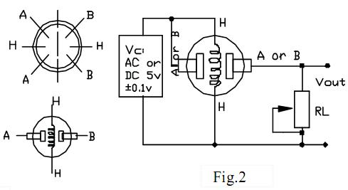
In the picture, the heater is for +5V and is connected to both 'A' pins. This is only possible if the heater needs a fixed +5V voltage.
The variable resistor in the picture is the load-resistor and it can be used to determine a good value. A fixed resistor for the load-resistor is used in most cases.
The Vout is connected to an analog input of the Board designed
The voltage for the internal heater is very important.
Some sensors use 5V for the heater, others need 2V. The 2V can be created with a PWM signal, using analogWrite() and a transistor or logic-level mosfet.
The heater may not be connected directly to an output-pin of the Arduino, since it uses too much current for that.
Some sensors need a few steps for the heater. This can be programmed with an analogWrite() function and delays. A transistor or logic-level mosfet should also in this situation be used for the heater.
If it is used in a battery operated device, a transistor or logic-level mosfet could also be used to switch the heater on and off.
The sensors that use 5V or 6V for the internal heater do get warm. They can easily get 50 or 60 degrees Celcius.
After the "burn-in time", the heater needs to be on for about 3 minutes (tested with MQ-2) before the readings become stable.
The sensor needs a load-resistor at the output to ground. It's value could be from 2kOhm to 47kOhm. The lower the value, the less sensitive. The higher the value, the less accurate for higher concentrations of gas.
If only one specific gas is measured, the load-resistor can be calibrated by applying a know concentration of that gas. If the sensor is used to measure any gas (like in a air quality detector) the load-resistor could be set for a value of about 1V output with clean air.
Choosing a good value for the load-resistor is only valid after the burn-in time.
Some datasheets use the term "preheat", but it is the time to burn-in the sensor. This is meant to make the sensor readings more consistent. A time of 12 or 24 hours is usually used for the burn-in time.
The Burn-in is achieved by applying normal power to the sensor (to the heater and with the 'A' and 'B' pins connected, and with a load-resistor). In some special cases a specific burn-in is needed. See the datasheet if the sensor needs such a specific burn-in.
Interesting links
MQ135 : A Sensor For Air Quality
- The heater uses 5V.
An example how to use it:
An example with calculation of the CO2 value:
Search for datasheet:
INPUT TESTERS
The first time i connected my sensor i decided made in an arduino MEGA, the idea is prototype things before connected to my board, i read that if i connected something wrong, i can damage the board or the sensor so i haven´t time an money for get another one and i will be disgutsting if any of both things happens!.
Other thing for consideration is the power need for works, at with the information i have the gas sensors can be operate from 2v to 5v this kind of modules, reading the datasheet, my need need a lot of power for works so it must to be connected at stable power supply with continuos 5v.
1. Burn the Sensor : As i mentioned before, the sensor must to be preheat from 12h to 24h for work fine, so i decided wired properly and connect the arduino to the other laptop.
2. After 20h i decided to test with basic examples codes founds at the arduino web page :
3. The Sensor works with basic so it´s time to callibrate it.


CALLIBRATION
I have some experience callibrating analog sensors but always with wrong methods, why? because always callibrated them as we say in spanish "a ojo" thats mean that never spent time reading the datasheet.... In fabAcademy i adquired the RTFM so first for callibrate this sensor is read the data sheet because the examples founds are always based in the MQ2 - Datasheet and every sensor from the family have differences at the curve exposures.
So this is the reference :


After studied all curve exposures, i decided to code a program who detect each gas mentioned, this learned to me what values are interesting for work.
So this is the reference i founded :
OUTPUT TESTERS
OutPut Devices : Milling a Leds Array and Piezo Board from Pilu Caballero on Vimeo.
POWER SUPPLY


COMMUNICATION TESTERS
My Kite must to be wiring trought a serial communications based in wires and non-wires, so i decided test first with the wires idea and deserve the non- wire for a future version connected to a cell phone.
The Master board for this network is based in a fabKit v.04 with atmega 328 and 8MHz crystal with the idea to use his 8mhz internal clock. This master must to by Power with a Lipo supply battery with the capability of be charged as many time as li-po life allow it because run the main sensor. The MQ 135 air quality sensor.
The Node based in another FabKit v 0.4 version with same technical data as the Master which receives the input devices values in a range for emiting some leds blink messages.
PROGRAMMING PROCESSES
During te reference process, i found some interesting things like an specif library for arduino called MQ - 135 library. As all contributed libraries, was made for help to people like me, because after i was reading, more and more, all people had bad experiences with the lecture of Gas Sensor Values and Datas.
Obviously, i was thinking about how i will be complicated with the sensor, which data i will receive, how i will to get the correct values for map them and callibrate according with the alttitude when my kite is not sewed and of course my sensor dont go more tham my window ....
So this is the extract from HackaDay web page where you will to find some interesting links such the GitHub link with the library and comments.
The datasheet claims that the MQ135 is sensitive for CO2, Alkohol, Benzene, NOx, NH3 and the Fig 3 shows the change in resistance depending on the concentration of these gases in the ambient air in ppm (of the total gas volume). It turns out the the general sensitivity is the roughly same for all the gases. This is where you think: CO2 is the 4th most abundant trace gas in the earths atmosphere with about 400ppm concentration (N2, O2, and Ar are on place 1-3).
All of the other gases the sensor detects are much less common than CO2 and luckily so, as they are harmful. This means, in a normal atmosphere the sensor mostly detects CO2 and with the right calibration we can use it as a cheap replacement for the MQ811 (which by the way is also sensitive to other gases).
Great explanation of David Gironi for the details, but mostly he just extracts data from the figures in the datasheet, throws some math at the problem and cross-checks the results with a different kind of sensor for CO2.
The MQ 135 Library basically just implements his approach for the Board designed. It's pretty easy to use. Copy it to your Arduino library folder and put it. Restart the application and you can see at the Sketchbook Folder.
Here are the code References for this library : The code begin including the library and declaring the main variable for the Analog Input Sensor :
#include <MQ135.h>

MQ135 gasSensor = MQ135(ANALOGPIN);
ANALOGPIN is the ADC input for the sensor readings
.Before use the sensor, it need to be callibrated as i mentioned with burn in process, then i put it into outside air (fix to my window), preferably at 20°C/35% rel. hum. ( but this days we have at Madrid more than 20º, we have 30º, the humidity is not so crucial for the moment ). Read out the calibration value as such :
float rzero = gasSensor.getRZero();
Wait until the value has somewhat settled (30min-1h). This is an ADC measurement so you might not want to wait some time between reading the sensor and also do some averaging. Once you have determined your RZero, put it into the MQ135.h. file in my libraries folder for MQ 135.
#define RZERO 76.63
The library also provides functions to apply the temperature/humidity correction that is shown in Fig 4 of the datasheet.
INPUT TESTERS
Code for test at Arduino IDE :
Digital TEST : This is a test reference based in arduino examples with MQ2 sensor without the library described above which i modified just for learn how the sensor works and have a basic code with serial communication for print a simple message when detects gas presence :
int pin_mq = 7; // The Analog pin

void setup() {
  Serial.begin(9600); // Initialize Serial Communication with 9600 baudrate the appropiated for my board designed
  pinMode(pin_mq, INPUT); // indicate the pin mode for teh sensor such an input
}

void loop() {

  boolean mq_estate = digitalRead(pin_mq);//Reading the Sensor
  if(mq_estado) // If the sensor output is 1
  {
    Serial.println("POLLUTION RISK");
  }
  else // If the output sensor is 0
  {("NOT POLLUTION RISK");
  }
  delay(100);
}
ANALOG TEST :
BASICS
void setup() {
  Serial.begin(9600);
}

void loop() {

  int adc_MQ = analogRead(7); //Lemos la salida analógica del MQ
  float voltaje = adc_MQ * (5.0 / 1023.0); //Convertimos la lectura en un valor de voltaje

  Serial.print("adc:");
  Serial.print(adc_MQ);
  Serial.print("    voltaje:");
  Serial.println(voltaje);
  delay(100);
}
Callibration Codes
1. Basic Callibration
void setup() {
  Serial.begin(9600);
}

void loop() {

  int adc_MQ = analogRead(A0); //Lemos la salida analógica  del MQ
  float voltaje = adc_MQ * (5.0 / 1023.0); //Convertimos la lectura en un valor de voltaje
  float Rs=1000*((5-voltaje)/voltaje);  //Calculamos Rs con un RL de 1k
  double alcohol=0.4091*pow(Rs/5463, -1.497); // calculamos la concentración  de alcohol con la ecuación obtenida.
  //-------Enviamos los valores por el puerto serial------------
  Serial.print("adc:");
  Serial.print(adc_MQ);
  Serial.print("    voltaje:");
  Serial.print(voltaje);
  Serial.print("    Rs:");
  Serial.print(Rs);
  Serial.print("    alcohol:");
  Serial.print(alcohol);
  Serial.println("mg/L");
  delay(100);
}
2. Callibration in Details
/*
  Arduino MQ135
  connect the sensor as follows :
  A H A   >>> 5V
  B       >>> A0
  H       >>> GND
  B       >>> 10K ohm >>> GND

  Contribution: epierre
  Based on David Gironi http://davidegironi.blogspot.fr/2014/01/cheap-co2-meter-using-mq135-sensor-with.html
  http://skylink.dl.sourceforge.net/project/davidegironi/avr-lib/avr_lib_mq135_01.zip

*/

#include <SPI.h>
#include < MySensor.h>
#include < Wire.h>

#define CHILD_ID_AIQ 0
#define AIQ_SENSOR_ANALOG_PIN 0

#define MQ135_DEFAULTPPM 399 //default ppm of CO2 for calibration
#define MQ135_DEFAULTRO 68550 //default Ro for MQ135_DEFAULTPPM ppm of CO2
#define MQ135_SCALINGFACTOR 116.6020682 //CO2 gas value
#define MQ135_EXPONENT -2.769034857 //CO2 gas value
#define MQ135_MAXRSRO 2.428 //for CO2
#define MQ135_MINRSRO 0.358 //for CO2

unsigned long SLEEP_TIME = 30000; // Sleep time between reads (in seconds)
//VARIABLES
float mq135_ro = 10000.0;    // this has to be tuned 10K Ohm
int val = 0;                 // variable to store the value coming from the sensor
float valAIQ =0.0;
float lastAIQ =0.0;

MySensor gw;
MyMessage msg(CHILD_ID_AIQ, V_LEVEL);

void setup()
{
  gw.begin();

  // Send the sketch version information to the gateway and Controller
  gw.sendSketchInfo("AIQ Sensor MQ135", "1.0");

  // Register all sensors to gateway (they will be created as child devices)
  gw.present(CHILD_ID_AIQ, S_AIR_QUALITY);

}

/*
 * get the calibrated ro based upon read resistance, and a know ppm
 */
long mq135_getro(long resvalue, double ppm) {
return (long)(resvalue * exp( log(MQ135_SCALINGFACTOR/ppm) / MQ135_EXPONENT ));
}

/*
 * get the ppm concentration
 */
double mq135_getppm(long resvalue, long ro) {
double ret = 0;
double validinterval = 0;
validinterval = resvalue/(double)ro;
if(validintervalMQ135_MINRSRO) {
ret = (double)MQ135_SCALINGFACTOR * pow( ((double)resvalue/ro), MQ135_EXPONENT);
}
return ret;
}

void loop()
{
  uint16_t valr = analogRead(AIQ_SENSOR_ANALOG_PIN);// Get AIQ value
  Serial.println(val);
  uint16_t val =  ((float)22000*(1023-valr)/valr);
  //during clean air calibration, read the Ro value and replace MQ135_DEFAULTRO value with it, you can even deactivate following function call.
  mq135_ro = mq135_getro(val, MQ135_DEFAULTPPM);
  //convert to ppm (using default ro)
  valAIQ = mq135_getppm(val, MQ135_DEFAULTRO);

  Serial.print ( "Val / Ro / value:");
  Serial.print ( val);
  Serial.print ( " / ");
  Serial.print ( mq135_ro);
  Serial.print ( " / ");
  Serial.print ( valAIQ);


  if (valAIQ != lastAIQ) {
      gw.send(msg.set(MQ135_DEFAULTPPM+(int)ceil(valAIQ)));
      lastAIQ = ceil(valAIQ);
  }

  // Power down the radio.  Note that the radio will get powered back up
  // on the next write() call.
  gw.sleep(SLEEP_TIME); //sleep for: sleepTime
}


/*****************************  MQGetPercentage **********************************
Input:   rs_ro_ratio - Rs divided by Ro
         pcurve      - pointer to the curve of the target gas
Output:  ppm of the target gas
Remarks: By using the slope and a point of the line. The x(logarithmic value of ppm)
         of the line could be derived if y(rs_ro_ratio) is provided. As it is a
         logarithmic coordinate, power of 10 is used to convert the result to non-logarithmic
         value.
************************************************************************************/
int  MQGetPercentage(float rs_ro_ratio, float ro, float *pcurve)
{
  return (double)(pcurve[0] * pow(((double)rs_ro_ratio/ro), pcurve[1]));
}
Networking: Master Test I from Pilu Caballero on Vimeo.
FINAL PROJECT PROCESS ANSWERS
WHAT IS THE DEADLINE ?
I presented my Final Project 14th of June so i had 3 weeks for develope my Final Project considering that i have a job and of course our FabLab open from 8 to 18.00h, so the real timeline was :
NIGHTS FOR DESIGN
AFTERNOOM FOR FABRICATED
THURSDAYS AND FRIDAYS FABLAB INTENSIVE
WHAT TASK HAVE BEEN COMPLETED?
Design 2D and 3D - Done!
Fabrication : Technologies involves Laser Cutter Machine, 3D Printer, Miller Machine, Sewing Machine -Done!
Assembled : Sew and Build : Done!
Electronics : Input, Output, Power SupplyBoards - Done!
Programming : Callibration, Detection, Serial Communication, NetWorking : Master+Slave, Imput Sending data values to output - Done!
WHAT TASK REMAIN?
Programming : I don´t considered this task at the first moment but i must to Store Input Data Values to Eprom memory by suggestion to my instructor.
WHAT HAS WORKED?
All you can see here, all you can see at my Final Project Page :
WHAT HASN´T WORKED?
The Diedro Connectors design for assembled the leds is not finnished.
WHAT QUESTIONS NEED TO BE RESOLVE?
Programming : Actually i have some programs for Store Data at EPPROM but i shoul to mapped better the sensor in future.
WHAT ARE YOU LEARNED?
As you read above after at each processes followed i learn a lot but develope the project with bit time and less money was worried at the first moment so this changed my schedules sometimes. Adapt my job with a real timeline was difficult.
But now i have also learned the basics, during the diploma i increase my creativity, i founded new ways, new knowledges as i was searching. The working methods learn me a lot too. Documented as best as possible was a fantastic process for remember things, for explain my problems each week, for get conclusions, for advance thought my mistakes...Probably here are one of my favourite phrases:
IF YOU DON´T FAIL, NOT GAIN
And i ADD:
SHOW YOUR MISTAKES AND FAILS TO OTHERS
The most helped thing what you can DO FOR OTHERS!!
