Twelveth Week
OUTPUT DEVICES
ASSESSESMENTS
| HAVE YOU | TASK COMPLETED |
|---|---|
| Described your design and fabrication process using words/images/screenshots. | YES |
| Explained the programming process/es you used and how the microcontroller datasheet helped you | YES |
| Explained problems and how you fixed them | YES |
| Included original design files and code | YES |
GROUP PROJECT
| HAVE YOU | TASK COMPLETED |
|---|---|
| Measure The Power Comsuption of an Output Devices | YES |
NEIL´S LESSON
Index
REFERENCES AND IDEAS : LEARNING ABOUT PIEZOS AS AN OUTPUTS
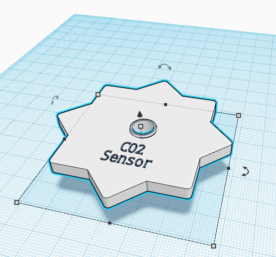
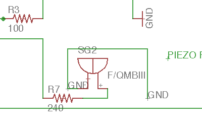
As my Final Project use leds for indicate levels of CO2, i decided design a board based in FabKit v.04 adding some leds with their appropiate resistors but as my instructor explain to me, to make an array of leds is an easy output device so i decided to add a Piezo Sensor for use it as an Output devices too (the piezo electrics can be used as analog sensors too for detect vibrations).
I founded some references images from here :
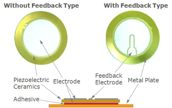
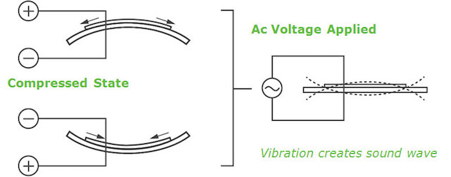
"At the heart of all piezo-type buzzers is the piezoelectric element. The piezoelectric element is composed of a piezoelectric ceramic and a metal plate held together with adhesive. Both sides of the piezoelectric ceramic plate contain an electrode for electrical conduction. Piezo materials exhibit a specific phenomenon known as the piezoelectric effect and the reverse piezoelectric effect. Exposure to mechanical strain will cause the material to develop an electric field, and vice versa."
There are two types of piezo buzzers - transducers and indicators. Transducers consist of a casing, a piezoceramic element and a terminal. In order to operate a transducer, the user must send a square wave signal to the buzzer. Indicators consist of a casing, a piezoceramic element, a circuit board and a terminal. In order to operate an indicator, the user must send the buzzer a specified DC voltage
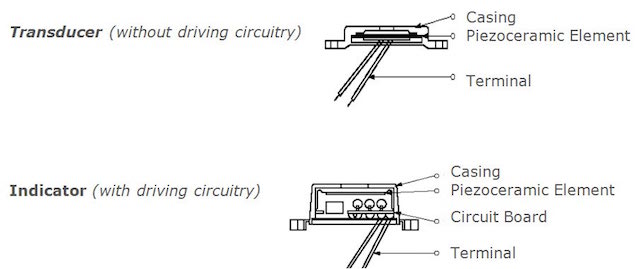
When an alternating voltage is applied to the piezoceramic element, the element extends and shrinks diametrically. This characteristic of piezoelectric material is utilized to make the ceramic plate vibrate rapidly to generate sound waves.
KEY SPECIFICATIONS
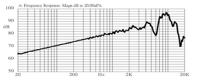
Frequency Response
- All things have a specific frequency at which they tend to vibrate. This frequency is called the resonant frequency. For buzzers, the resonant frequency is the frequency at which they will be the loudest.
-Electrical impedance is the ratio of applied voltage to current. The electrical impedance varies with frequency.
In a perfect world all devices would recreate every frequency at the exact same amplitude. In real life every device will have frequencies which it may amplify and frequencies which it will tend to reduce or attenuate. Frequency response curves show how a particular device responds to each frequency. SPL is plotted against frequency to indicate how the device will handle certain frequencies. Note: frequency is plotted on an exponential basis, similar to dB's, it allows the full range of human hearing to be fit in a compact space.
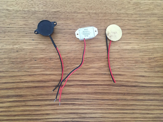
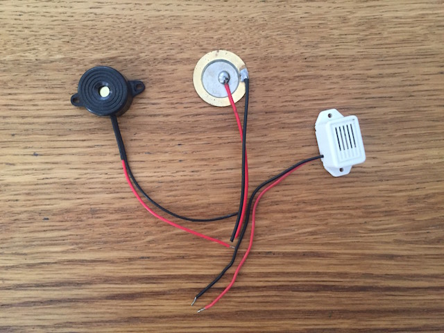
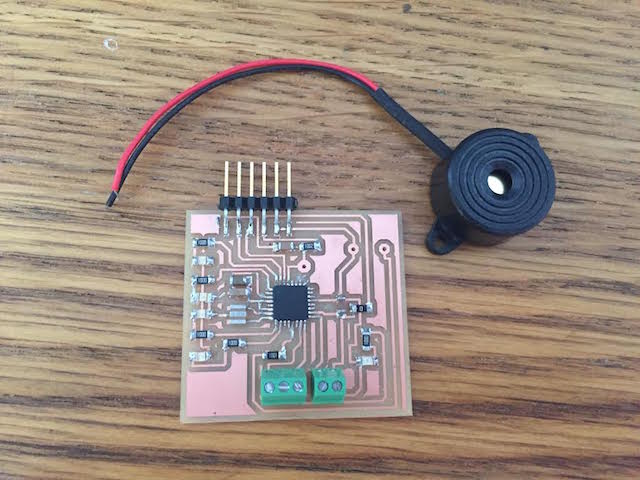
I decided to use one of i founded at my components box :
DESIGN TIME
I used Eagle agian for connect the ATmel 168 with the rest of smd components. I´m thinking in small boards so may i can learned more about how to order components at the board.
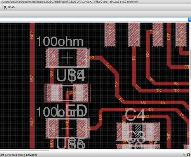
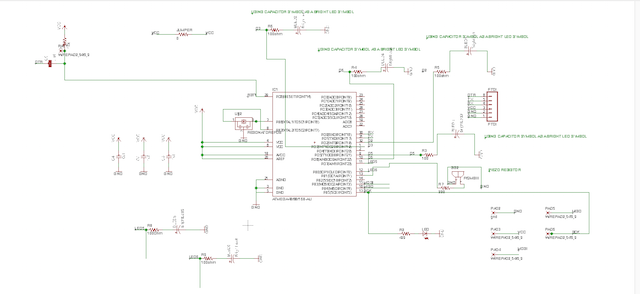
1. At the Schematic i changed some things, first u added the leds connecting them at the digital pins i desire :
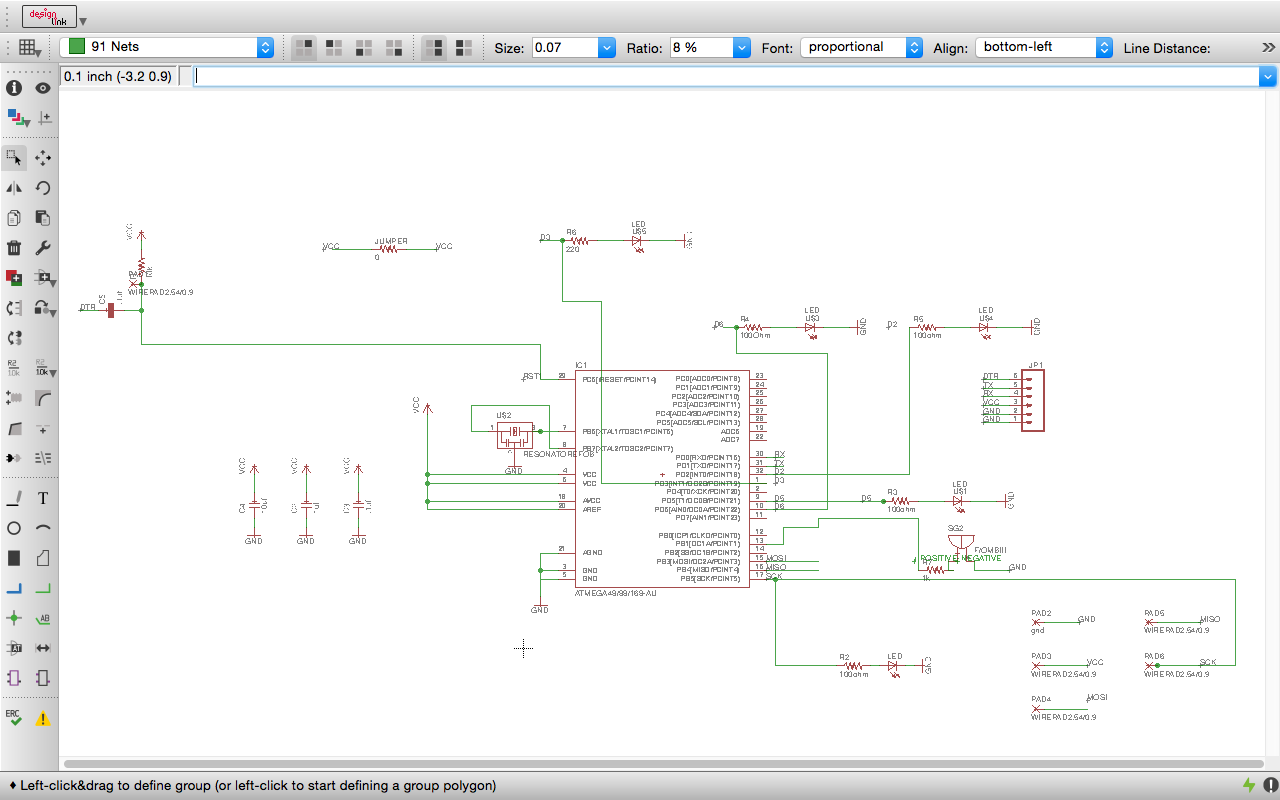
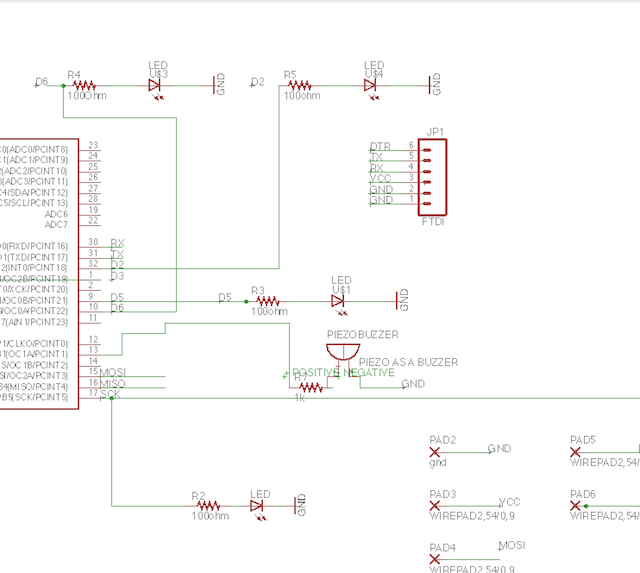
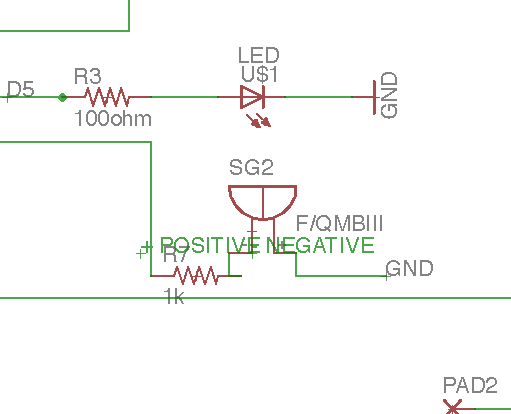
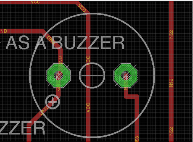
2. Later i decided to use another PWM (Pulse Width Modulation) for the piezo, la idea is that the piezo can emit sounds, melodys, alerts...
3. For finish i reconfigured some pins for order later all better and test with ERC and all looks fine.
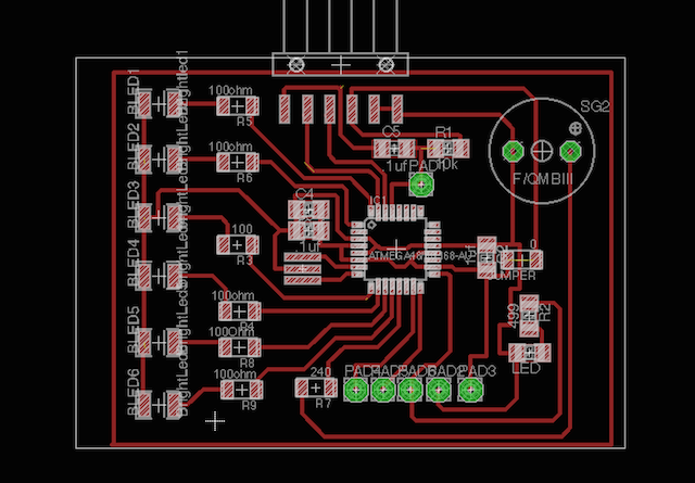
4. For make my board, order the elements such as "microBoard" but with the leds possition´s different. The rest of the components such as the Crystal or the capacitors i didn´t modified.
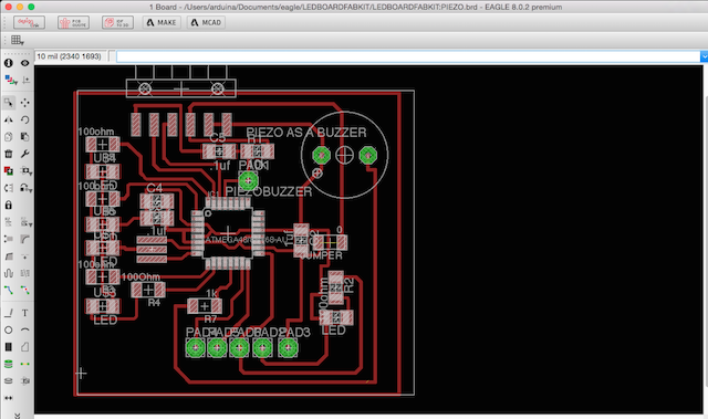
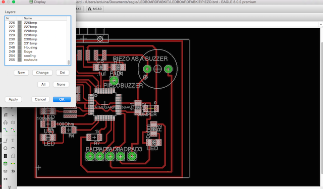
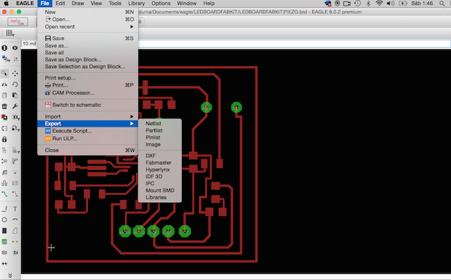
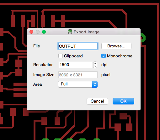
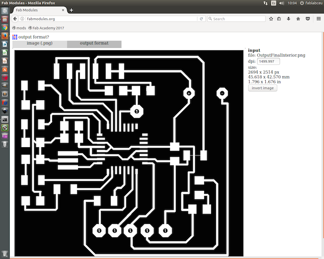
5. Finally i was checking with my DRC and just present things such stop Mask... so i was ready for prepare my board at Photoshop, exporting an image for this time at 1500 dpi resolution, as always with Monochrome mode.
6. At Ps, i opened the file and at Image > Cut >
7. Selected Image > Mode > GreyScale >
8. I resized the image canvas applying to each border the size of the mill, in my case 0,40mm
9. So now I selected the Magic Pen Tool > and selected this border made previosuly and apply white color with the tool and save the file for exprt later sucha as InteriorFile
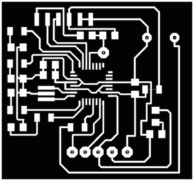
10. After this i selected the inverse and apply color to black, selected the inverse again and apply with for my exteriorfile.

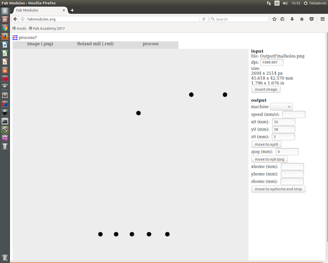
11. I had some holes for mill too so i must to do another file for them with the same selecting and color application technique and

MILLING TIME
Before mill, my instructor take a look to the board for be sure to all are ok so i milled the board:
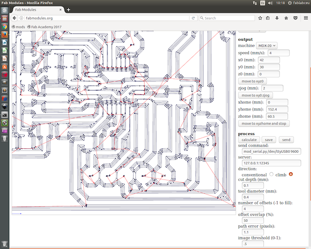
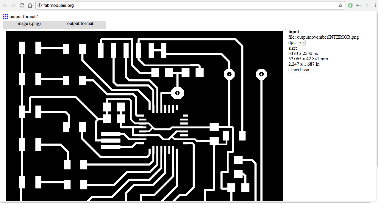
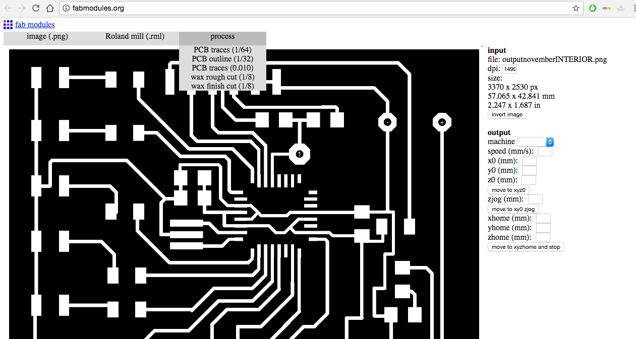
For milling the board i use for this time ./fab_modules.
1. I copied my file to the computer, open at terminal mods with this line of commands :
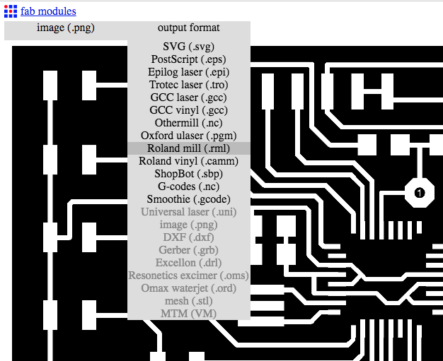
2. I imported the Interior file, selecting 1/64 traces and calculating after i made the origin.
3. I repeat the same thing for holesFile and outlinefile but selecting 1/32 traces.
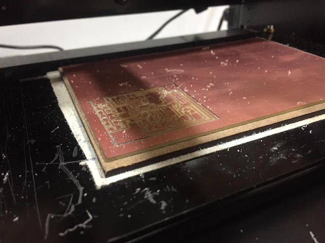
here is the result :
OutPut Devices : Milling a Leds Array and Piezo Board from Pilu Caballero on Vimeo.
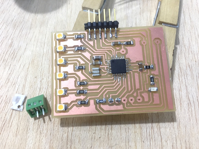
WELD TIME
Weld Tips followed :
1. Weld the Atmel 168 first, for not put extra iron on his traces and mix connections, for this, the use of tweezers are an assential.
2.After i made the capacitors and resistors.
3.Later the leds
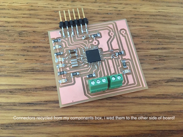
4. for finished y add the pin headers and wire connectors.
5.Time for check the connections with the multimeter .
WEEK PROBLEMS SOLVED
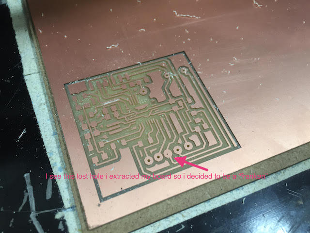
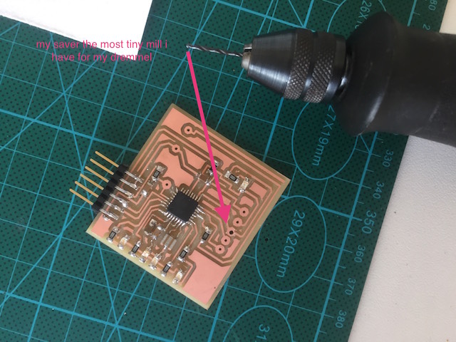
1ST. For this week i will to be a "Franken" again, as you can se at the pictures above, the modela ignore a hole present in the file and i thought that she works fine and extract my board before noticed this....but i solved as a "Franken" with my Dremmel and the most tiny mill i had.
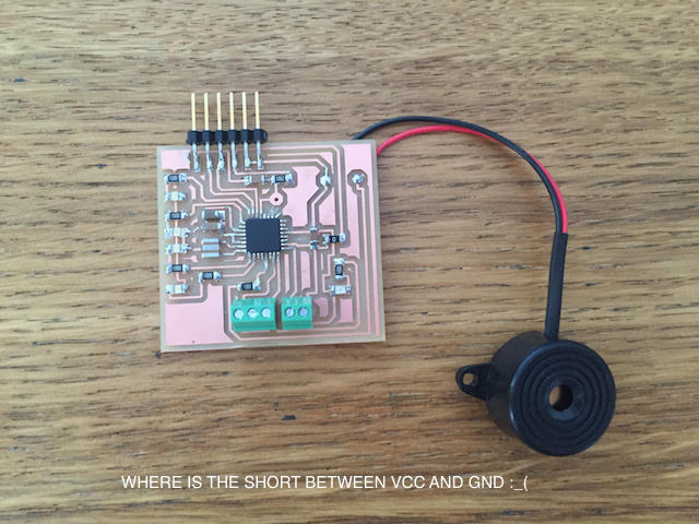
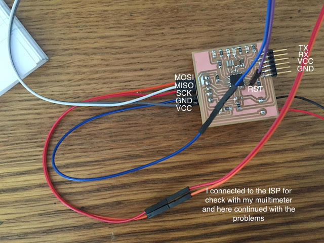
2ND. When i weld i connected GND with VCC so i have a short as a house.... I can´t believe! I was looking througt my lupe but i can´t find the mistake. One of the reason is the delay in made this assignment, today is Saturday, my Fablab close his doors, we are finishing and i forgot my unwelder too.... i want to cry but not so for have something i decided make a program for an Arduino Mega that i have.
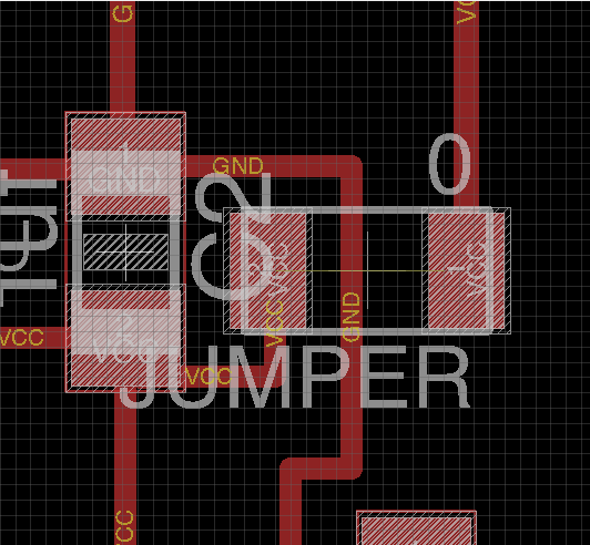
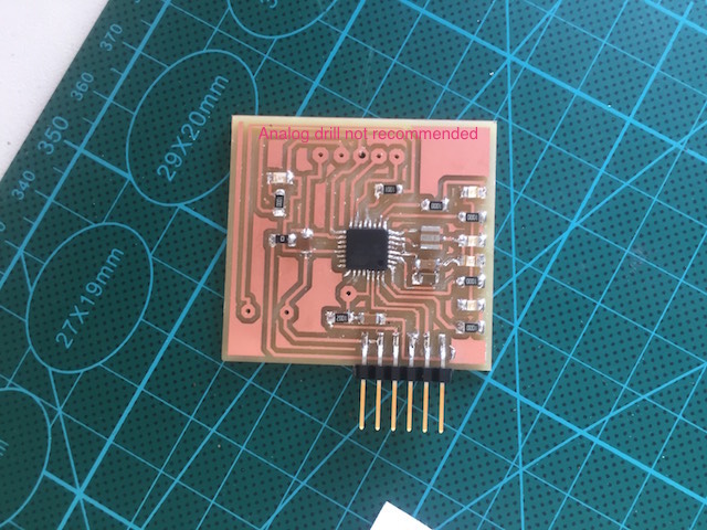
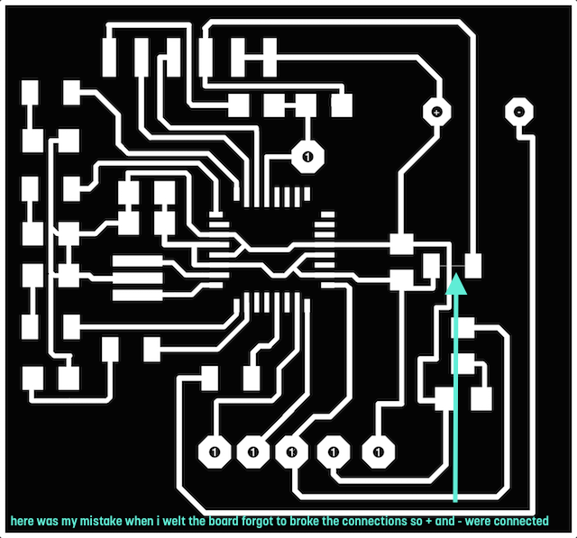
After looking some things at the design i founded some mistakes there, as you can see at the picture below, i forgot to delete at Photoshop, the minitraces for jumper resistor.
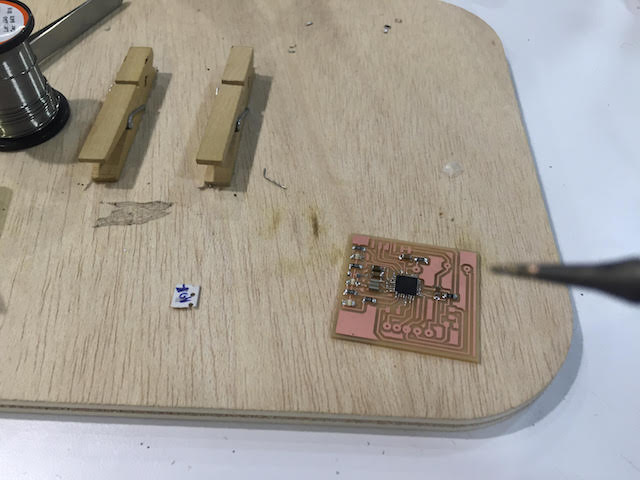
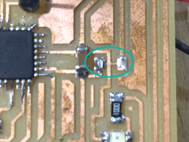
Finally, when i back to the fablab unwelt the jumper resistor and confirmed the mistake observed at the design :
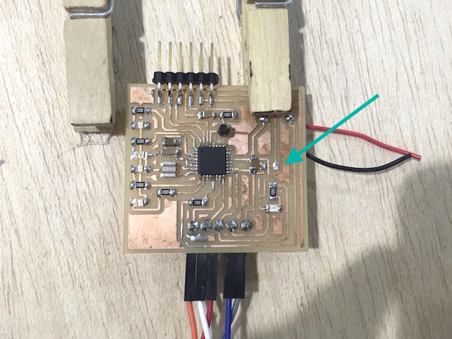
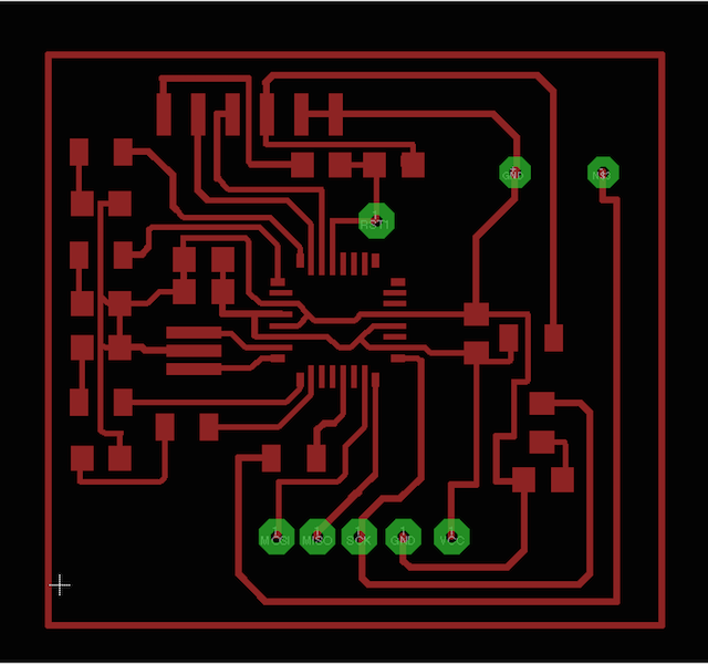
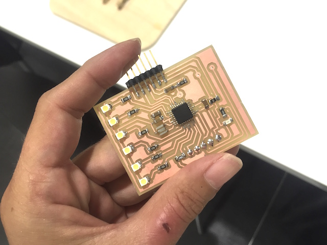
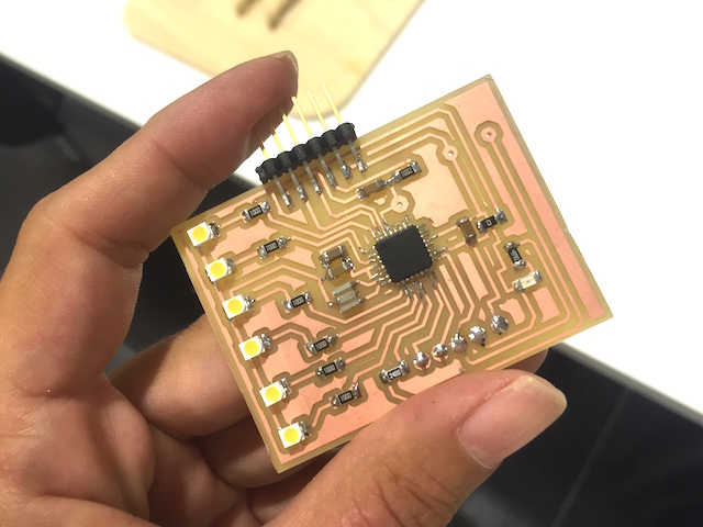
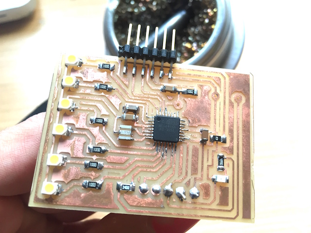
As my processor resulted burned when connect my board for first time, i decided redesigned the board and milled it again following the steps described before so here was the result about my new board :
I added new bright leds thinking in my final project, the idea is use them for practice. The process at the miller machine was using ./fabmodules again:

DATASHEET TIME : HOW TO HELP ME READING IT
I found this things from the Atmel 168 micro-processor about PWM pinout which are for my interest and can to help me to program better my board :
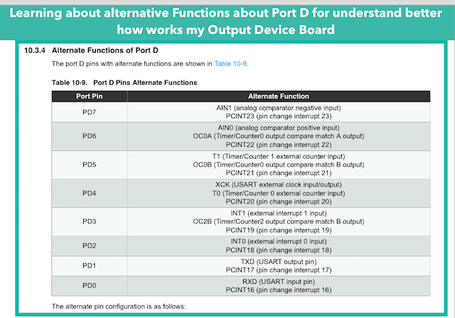
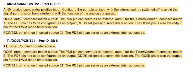
Not all Digital pins are PWM, important for control the intensity of my bright leds but i can convert the use of some.
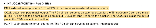
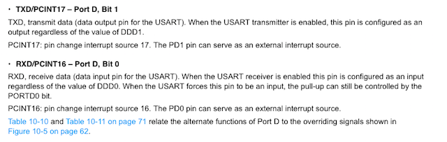

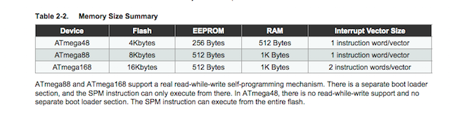
The memory is shorter so i will to write an appropiate program for my board, if i excess the memory the program doesn´t work properly.
The PWM section is really usefull for program tone functions with my board.
PROGRAMMING I : USING AND ARDUINO MEGA
When tell to my friend Marta what will to do with the programming she suggested me something fun like the basic nightRider example, so this gave me the idea to make a program for our favourite TV show and surprise her when i finish. As i decided to use Arduino IDE for programing here are the refrences founded at the Official page :
Some references codes :
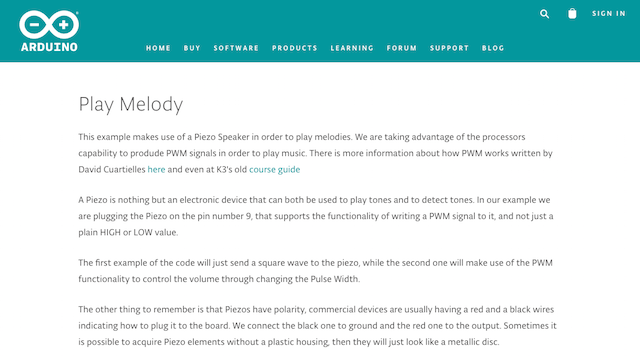
Another useful refrences codes from people outthere :
1st ATTEMP
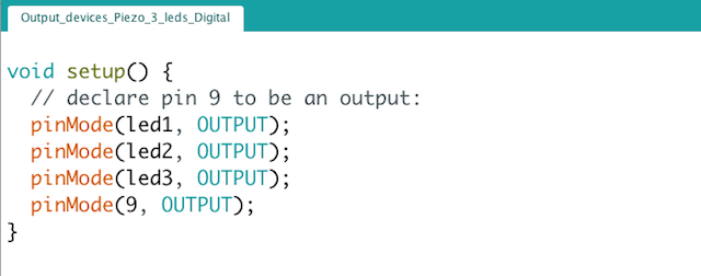
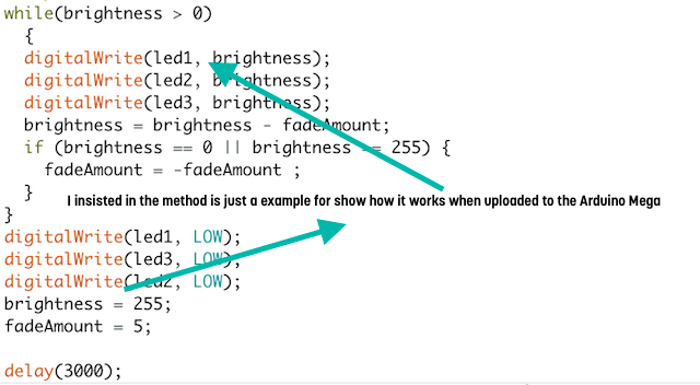
Obviously and i haven´t my board ready and always prototype my things first so i made one with an arduino MEGA .I have in my house 3 leds, why 3 leds and not 4? because i haven´t more, sorry!. So this is the code i made using the same pin i will use in my board for leds and the piezo. All are connected to PWM (Pulse Width Modulation) but for begin i used the led at maximum brightness 255.
I write the program for each led adjust to each note, but the idea i finish a song theme as an array for the notes configuring the bpm or frecuencies see at the refrences code. The code is extensive and spent some time developing but i think is nice for explain to my students how to assign a note to different leds and how to use main functions.
Here are some pics about the basics there :
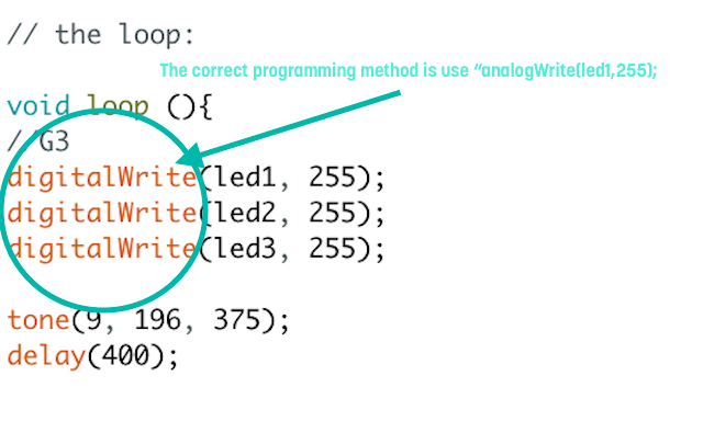
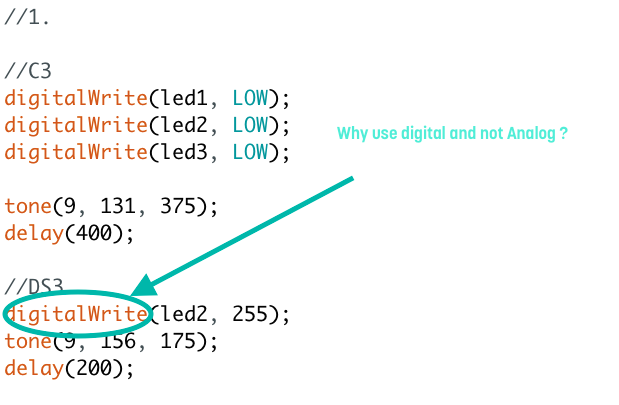
After some debuggins because i lost some notes..... You can see how it works with with wrong use of digitalWrite function.
SUMMER IS COMMING
So why is neccesary use the correct analogWrite function, because The analogWrite function has nothing to do with the analog pins or the analogRead function. Writes an analog value (PWM wave) to a pin. Can be used to light a LED at varying brightnesses. After a call to analogWrite(), the pin will generate a steady square wave of the specified duty cycle until the next call to analogWrite() (or a call to digitalRead() or digitalWrite() on the same pin). The frequency of the PWM signal on most pins is approximately 490 Hz.
PROGRAMMING II: Programs for my Output Devices Board
2nd ATTEMP
So i decided to write something thinking in my board once solved. The memory of Atmel 168 processor as i learned thanks to the Datasheet is shorter than the micro-controller used at the first attend (the Arduino Mega). I learned that the code will not to work properly so i decided simplify the things.
Using the things learned during my experience as programmer in the Machine Design Assignment and as i learned how to translate notes understandable by the computer, the idea is use them for made a code and use both outputs.
1. First i was testing my board for demostrate as the checks with multimeter was good. So i made the burn as i explained in other assignments and after this try the blink example on the led attached to my mosi pin.
Output Devices : Burning the bootloader from Pilu Caballero on Vimeo.
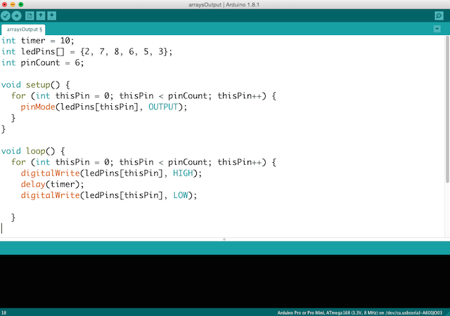
2. Later, i decided to make a program based on David Mellis founder on arduino IDE which practice the control´s structures at sintax. So here is the code :
int timer = 10;
int ledPins[] = {2, 7, 8, 6, 5, 3};
int pinCount = 6;
void setup() {
for (int thisPin = 0; thisPin < pinCount; thisPin++) {
pinMode(ledPins[thisPin], OUTPUT);
}
}
void loop() {
for (int thisPin = 0; thisPin < pinCount; thisPin++) {
digitalWrite(ledPins[thisPin], HIGH);
delay(timer);
digitalWrite(ledPins[thisPin], LOW);
}
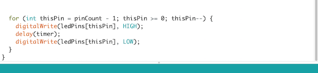
for (int thisPin = pinCount - 1; thisPin >= 0; thisPin--) {
digitalWrite(ledPins[thisPin], HIGH);
delay(timer);
digitalWrite(ledPins[thisPin], LOW);
}
}
Output Devices Programming I : Control Structures. Arrays. Bright Leds from Pilu Caballero on Vimeo.
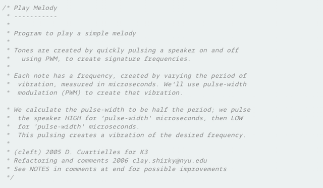
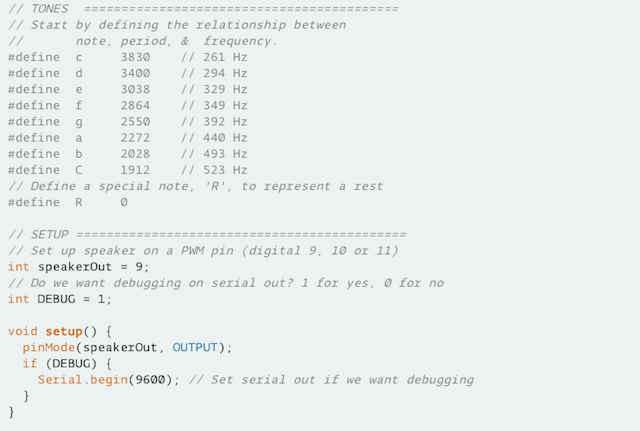
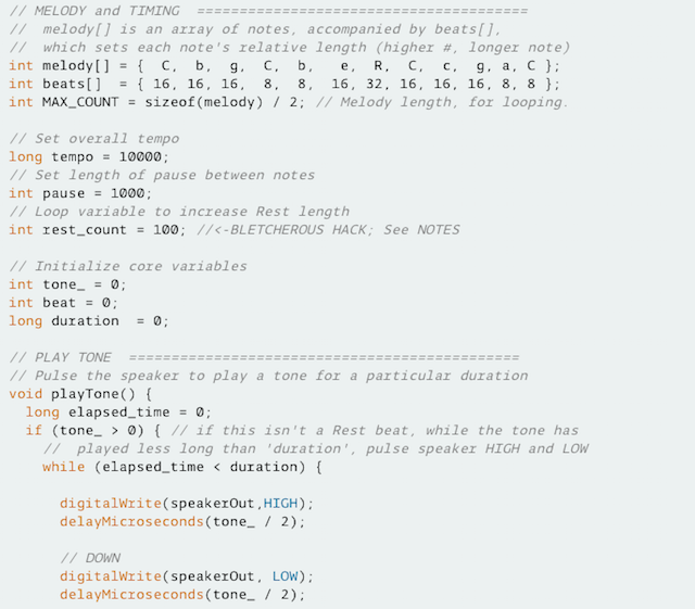
3. For Test the Piezo as a buzzer i decided to use the Tone Arduino Example founded at the IDE :
Output Devices : Programming II. Testing Arduino Tone Example from Pilu Caballero on Vimeo.
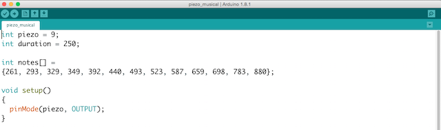
4. So all is working is time to write the program desired, for practice music notes i write this based in musical scale:
int piezo = 9;
int duration = 250;
int notes[] =
{261, 293, 329, 349, 392, 440, 493, 523, 587, 659, 698, 783, 880};
void setup()
{
pinMode(piezo, OUTPUT);
}
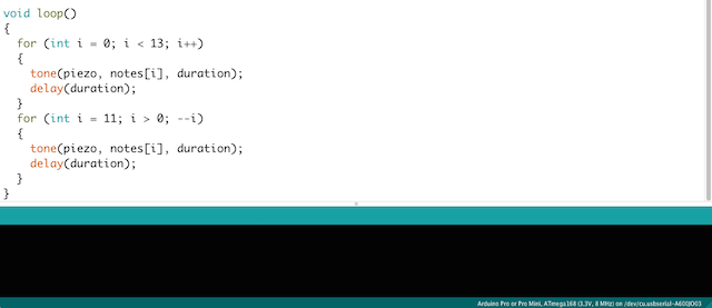
void loop()
{
for (int i = 0; i < 13; i++)
{
tone(piezo, notes[i], duration);
delay(duration);
}
for (int i = 11; i > 0; --i)
{
tone(piezo, notes[i], duration);
delay(duration);
}
}
Output Devices : Programming II. Writing my own code for piezo as an Output from Pilu Caballero on Vimeo.
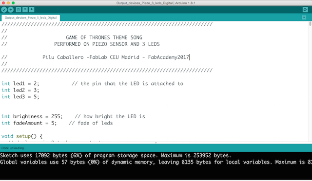
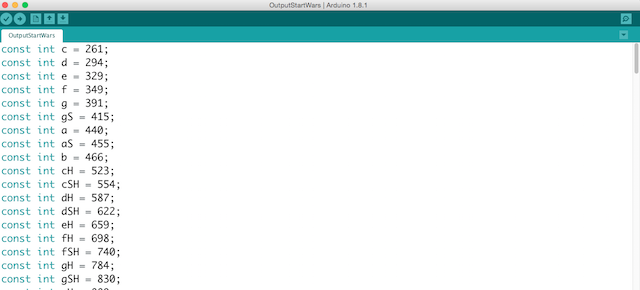
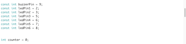
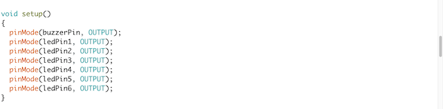
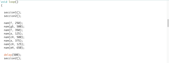
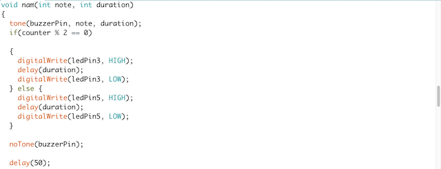
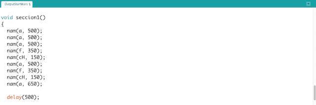
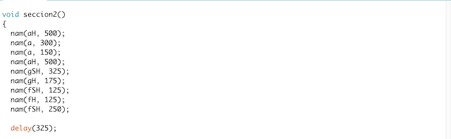
5. Finally i mix both for have the music of Force playing different bright LEDs depending on value of 'counter':
const int c = 261;
const int d = 294;
const int e = 329;
const int f = 349;
const int g = 391;
const int gS = 415;
const int a = 440;
const int aS = 455;
const int b = 466;
const int cH = 523;
const int cSH = 554;
const int dH = 587;
const int dSH = 622;
const int eH = 659;
const int fH = 698;
const int fSH = 740;
const int gH = 784;
const int gSH = 830;
const int aH = 880;

const int buzzerPin = 9;
const int ledPin1 = 2;
const int ledPin2 = 3;
const int ledPin3 = 5;
const int ledPin4 = 6;
const int ledPin5 = 7;
const int ledPin6 = 8;


int counter = 0;

void setup()
{
  pinMode(buzzerPin, OUTPUT);
  pinMode(ledPin1, OUTPUT);
  pinMode(ledPin2, OUTPUT);
  pinMode(ledPin3, OUTPUT);
  pinMode(ledPin4, OUTPUT);
  pinMode(ledPin5, OUTPUT);
  pinMode(ledPin6, OUTPUT);
}

void loop()
{

  seccion1();
  seccion2();

  nam(f, 250);
  nam(gS, 500);
  nam(f, 350);
  nam(a, 125);
  nam(cH, 500);
  nam(a, 375);
  nam(cH, 125);
  nam(eH, 650);

  delay(500);
  seccion2();

  nam(f, 250);
  nam(gS, 500);
  nam(f, 375);
  nam(cH, 125);
  nam(a, 500);
  nam(f, 375);
  nam(cH, 125);
  nam(a, 650);

  delay(650);
}

void nam(int note, int duration)
{
  tone(buzzerPin, note, duration);
  if(counter % 2 == 0)

  {
    digitalWrite(ledPin3, HIGH);
    delay(duration);
    digitalWrite(ledPin3, LOW);
  } else {
    digitalWrite(ledPin5, HIGH);
    delay(duration);
    digitalWrite(ledPin5, LOW);
  }

  noTone(buzzerPin);

  delay(50);
  counter++;
}

void seccion1()
{
  nam(a, 500);
  nam(a, 500);
  nam(a, 500);
  nam(f, 350);
  nam(cH, 150);
  nam(a, 500);
  nam(f, 350);
  nam(cH, 150);
  nam(a, 650);

  delay(500);

  nam(eH, 500);
  nam(eH, 500);
  nam(eH, 500);
  nam(fH, 350);
  nam(cH, 150);
  nam(gS, 500);
  nam(f, 350);
  nam(cH, 150);
  nam(a, 650);

  delay(500);
}

void seccion2()
{
  nam(aH, 500);
  nam(a, 300);
  nam(a, 150);
  nam(aH, 500);
  nam(gSH, 325);
  nam(gH, 175);
  nam(fSH, 125);
  nam(fH, 125);
  nam(fSH, 250);

  delay(325);

  nam(aS, 250);
  nam(dSH, 500);
  nam(dH, 325);
  nam(cSH, 175);
  nam(cH, 125);
  nam(b, 125);
  nam(cH, 250);

  delay(350);
}
Output Devices : Programming II. Piezo & Leds : The Force from Pilu Caballero on Vimeo.
THINGS I LEARNED
Electornic theory about Piezo electrics and which resistors can be use with them.
Every mistake learned to me i must to focuss better during my design time.
How to recognize new registers at the DataSheet for the AtMel 328p. I was navigating both datasheets so this week i advance with possible micro-processors for the final project board.
About programming i was playing discovering some things first with the arduino mega, later with my own board.
WEEK CONCLUSIONS
After some ideas the best conclusion was focuss on my Final Project for advance in programming later.
WEEK FILES
GROUP PROJECTS
For this year we must to make some practices in group so Lucio and i decided to made basic testers.
How contribute for this task group? First of all i organize the works for to do in time, also develope the web site for this week explaining there all things worked together and individually.
We used this design made the last year for measure the Power Comsuption about the bright leds and the Piezo.
So for see the experiments made together please visit our Group Project´s website here :
MY FINAL PROJECT
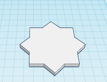
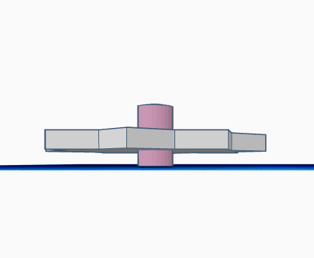
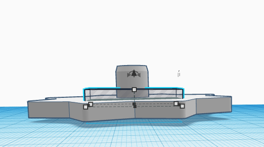
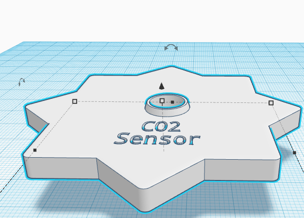
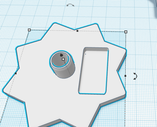
I decided to begin with a possible desing for the ROD with same software used for the 2ND part of the assignment with the idea to spent bit time and try to mould this design for a possible cast in future.