Eleventh Week
INPUT DEVICES
ASSESSESMENTS
| HAVE YOU | TASK COMPLETED |
|---|---|
| Described your design and fabrication process using words/images/screenshots. | YES |
| Explained the programming process/es you used and how the microcontroller datasheet helped you | YES |
| Explained problems and how you fixed them | YES |
| Included original design files and code | YES |
GROUP PROJECT
| HAVE YOU | TASK COMPLETED |
|---|---|
| Measure analog and digital signals from an input device | YES |
NEIL´S LESSON
Index
| HAVE YOU | TASK COMPLETED |
|---|---|
| Explained how you made your files for machining | YES |
| Shown how you made your mould and cast the parts | YES |
| Explained problems and how you fixed them | YES |
| Included your design files and ‘hero shot’ photos of the mould and the final object | YES |
DESIGN TIME
I´m really interested in capacitive sensors because i´m developing a serie of them based in chemical crystals what i made exploring the posibilities of disciplines mixing such as Chemistry, Creativity, Electronics and Sound Art. How a girl from letters know things about chemistry? Probably you are asking this...
My mom is biochemist and when i was a child he learn me a lot about chemist science spending my saturdays at her lab.
I can´t to share all the experiment for the time. The main reason is because still experimenting with mix quantities and chemist components and my idea is write a paper with the study in the future because i have a lot test with thermochromics pigments too!!.
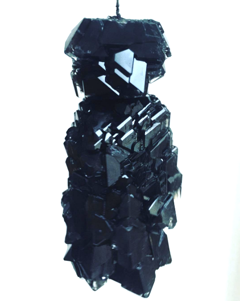
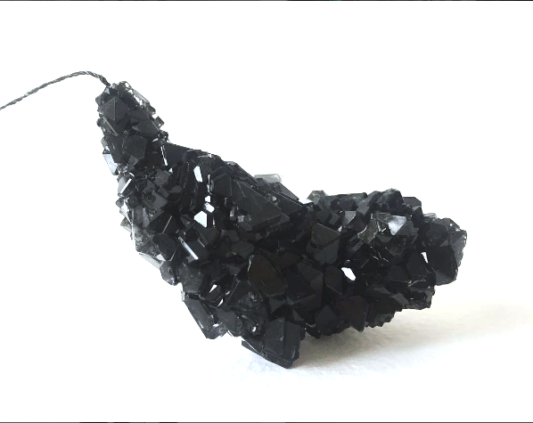
But the basics i´m doing is to modify the "Carbon Alotrophes Secuence" which the result of awesome and fantastic crystals with different durabilities but the most important for my artistic purpose is that them are "Conductive". I can try how to works with a capacitive commercial board such as TouchBoard from BarePaint so my own goal is make something with the week assignments and my "Analog Crystal Sensors" :
Input Devices : My Analog Crystal Sensors from Pilu Caballero on Vimeo.
As you can see at the video, i made a Conductive Crochet Chain with Conductive Thread and this worked as a seed for the grow of them.
So i decided redesign the touchBoard example from Neil. The first Design i made was the load board with the Attiny 45 , but my instructor suggested us about the use of Atmel 168 or 328 for serial communication, main thing for read the sensor values trought to the serial monitor.
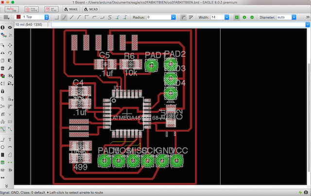
I used Eagle again for design the board, the first mistake i had was with the design, i was tired and connected my resistor following wrong ways.
At thursday, decided start from the begining again reading the datasheet about 168 micro-controller, studing the examples from Neil. Here are the essential references :
We can made a simple board called LOAD :
Or One more precise based in transmiter and receive principle :
I decided make the last one, for have more precission with my experimental sensors and clear things with them at the measurument.
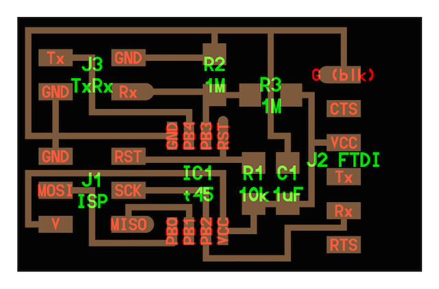
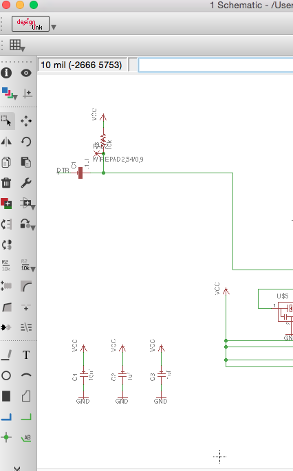
On Friday morning start with the design, i got the fabkit and was deleting all things not necessary for my new board :
As our instructor said, if we need to be little "Frankensteins" we will be, the important thing is try and attend for advance and learn about our new design and how to code it.
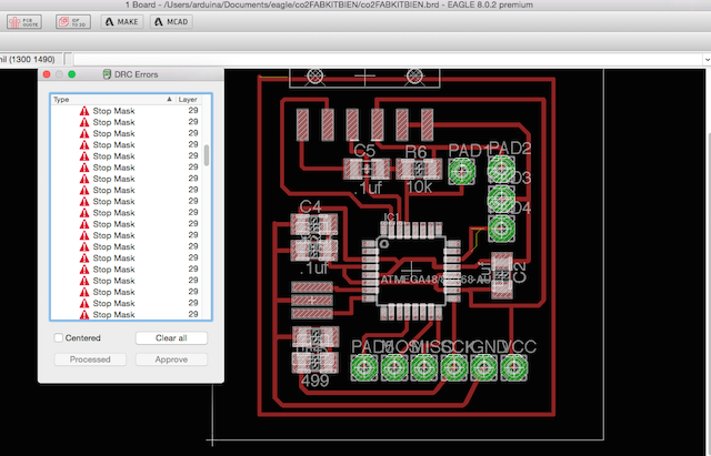
Route the traces was a stress task, we was 3 students for mill our boards in a day, the machine has not been working as it should have during the last weeks so we was with our cross fingers and specially me the last in mill...

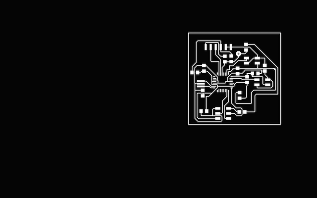
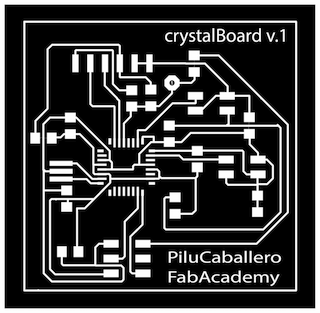
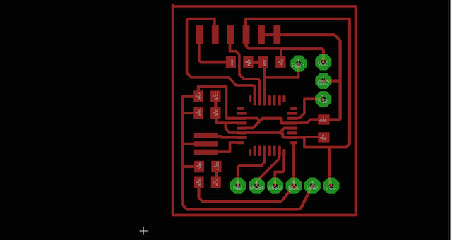
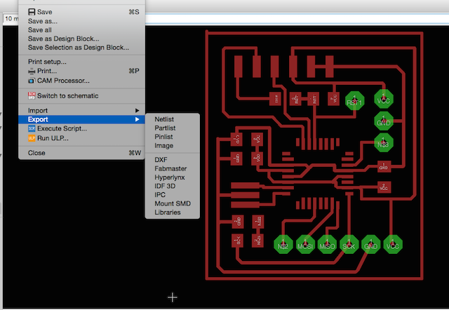
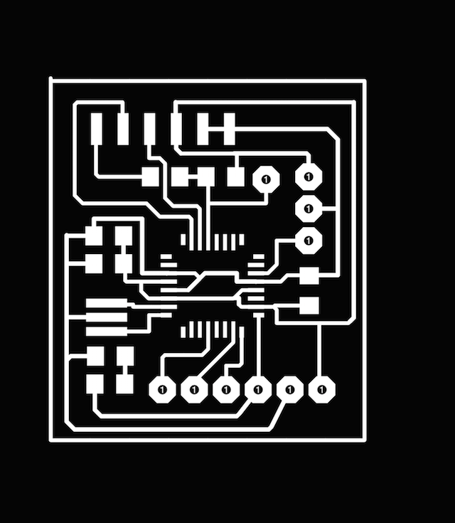
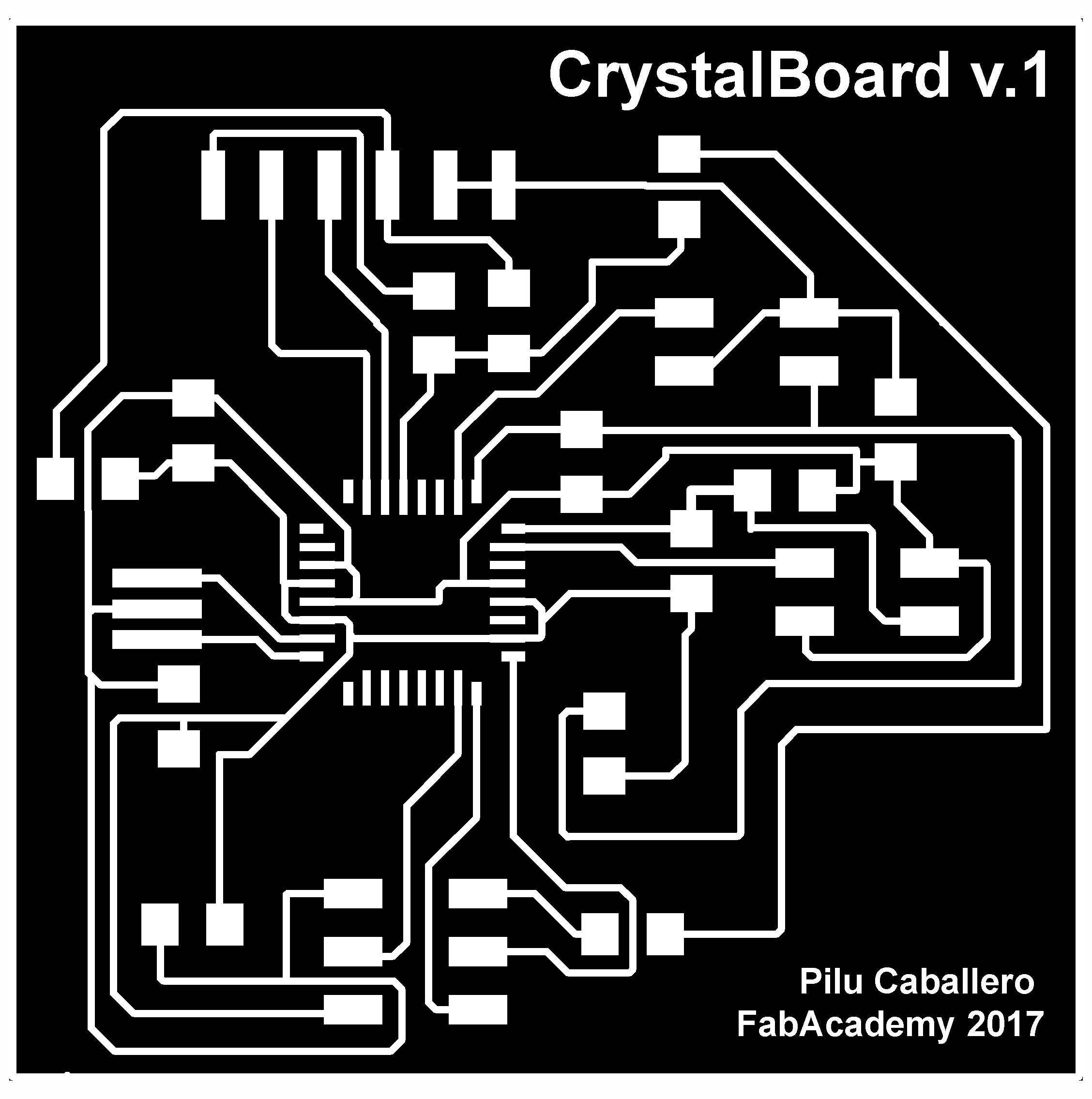
Finished my design, i export an image with 1200 dpi of resolution with Monochrome style for work with it at Photoshop, where i made the final image for send to the Modela MDX 20 througth mods, the steps i followed was :
1. Open the image at PS and at the contextual menu, selected : image > Cut >
2. At Image > Selected Mode > and GREY SCALE >
3. At Image Size > I added the size our mill for cut in my case 3,6 mm to each side of the board. Here is where i selected and apply white color saving my file.
4. For make the interior Select Image > Transform > Magic Pen > Select and colorfull with white.
5. Selecting the inverse i made the exterior traces colurfull with black

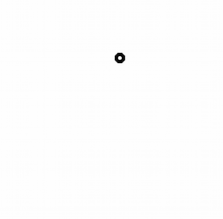
6. As i have a pad for this design i made another layout for cut it at the milling process
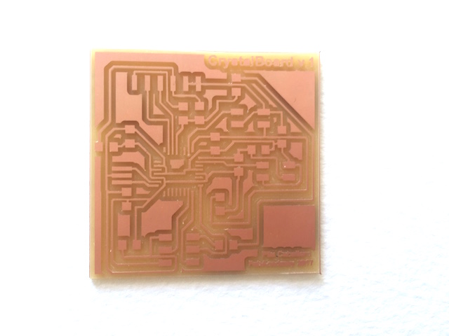
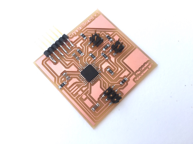
Finally i had my board for milled
FABRICATION TIME
MILLING PROCESS
I had just 30 minutes for mill my board, the girl that close our fablab at 18:30h the Fridays gently wait to me for have something with work the next 5 days because the University where we are close from Friday to Wednesday, so i thought about my uncertain lucky time hahahaha...
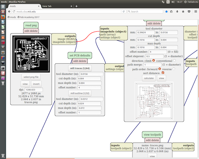
1. Mods was opened because my classmate Alavaro was milling his board so i exported my .png files from my USB to the computer copied them, i opened the interior file first selecting 1/64 mill traces with 4 at Offset.
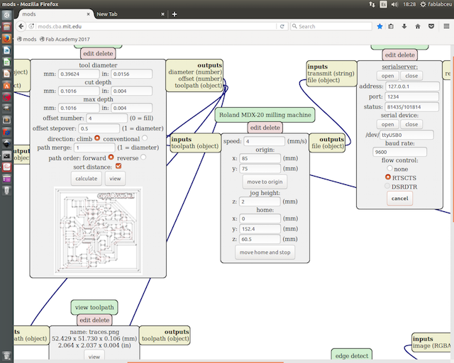
2. Made the Origin for put the mill at the position interested
3. Calculated for check how the mill work
4. Finally i send the file to the machine
As you can see at the pic below, the board have the first traces without mill, i think that can be that the board is not fixed well to the base, after this, the machine lost the server communication so i made the connection again at terminal for continue, but not began well...
The Milling Problems
The resolution is less than adecuate for the machine and didn´t mill well some traces.
My mistake making the pad files for cut at photoshop made a big hole but i can solve this applying more weld.
1st Attempt to Solve
i was trying to solve the problems but the traces was designing with 12.00 mm and they up breaking the board and the most important thing the chip.
2nd Attempt
I milled again my board correcting some things at the design such the hole with the same resolution for clear things with the other milled process and learn more, as you can see, for this time, the modella work without problems.
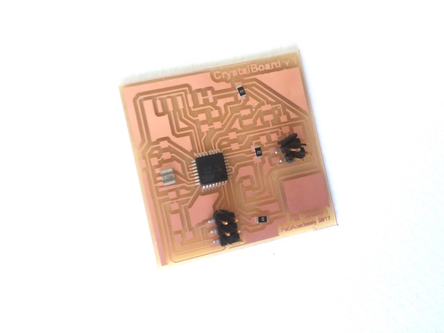
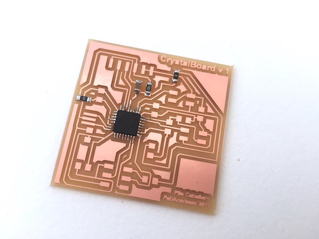
WELD TIME
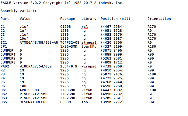
First, this the BOM i made for the "CrystalBoard v.1 :
| Name | Inventory | Fab Library Symbol |
|---|---|---|
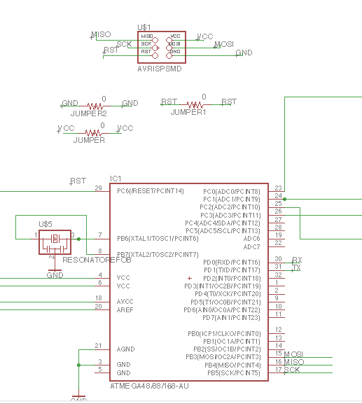
| 1X 6-pin programming header | 649-95278-101A06LF | AVRISPSMD |
| 1X Microcontroller: 168U | ||
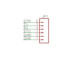
| 1X FTDI header : Powers the board and allows board to talk to computer | CONN HEADER 36POS .100 R-A SMD (S1143E-36-ND) | FTDI-SMD-HEADER |
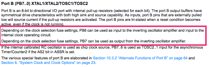
| 1X 20MHz resonator : external clock. The attiny has a 8Mhz clock but the resonator is faster (increase the clock speed of the processor) and more accurate. | CER RESONATOR 20.00MHZ SMD (XC1109CT-ND) | RESONATOR |
| 2X Resistor | RES 10.0K OHM 1-4W 1% 1206 SMD (311-10.0KFRCT-ND) | RES-US1206FAB |
| 4 Resistor : (value 1M) | 11-1FRCT-ND | RES-US1206FAB |
| 1 Resistor : (value 100k) | 311-100FRCT-ND | RES-US1206FAB |
DATASHEET TIME : THINGS LEARNED READING IT AND HOW TO HELP ME
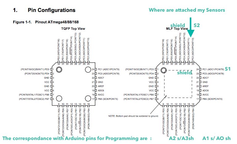
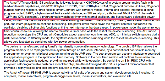
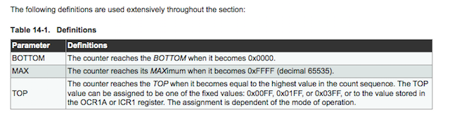
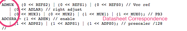
I was studing the Atmel 168 micro-processor data sheet, here is the general for all micro-processors :
Things i learned from there :
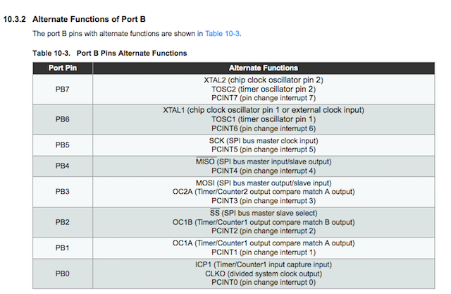
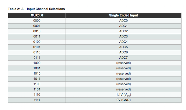
1. Where my sensor is attaeched looking Pin configurations.
ABOUT ELECTRONICS DESIGN :
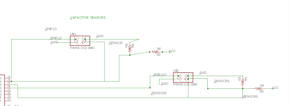
The sensor should to work TX connected to the Crystal Sensor while RX connected to VCC Divider and GND connected to the pin. So RX is connected inside with the Crochet Chain made previously and the TX is around.
If the difference between voltage in both sensors connected is bigger, the serial monitor will show a large number. As more close the values down to 0.
ABOUT PROGRAMMING:
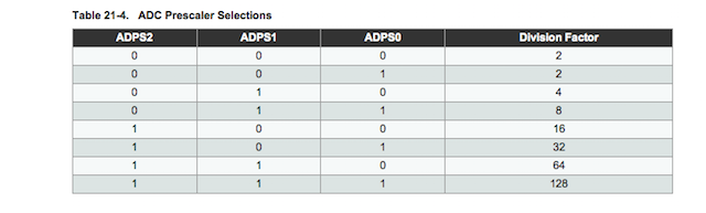
The input program should to prescale the pin´s clock that goes to the Crystal Sensors for measure the tension data and to make teh same with the Receiver data.
PROGRAMMING AND TESTING I : PROGRAMMING WITH ARDUINO
CODING TIME
The references for coding the board need to be explain with how works a capacitive sensor, here are usefull and quick references about it:
The Arduino reference explain in details how this sensors works, which libraries should to be installed for write prgrams for them at arduino IDE and basic examples for begin.
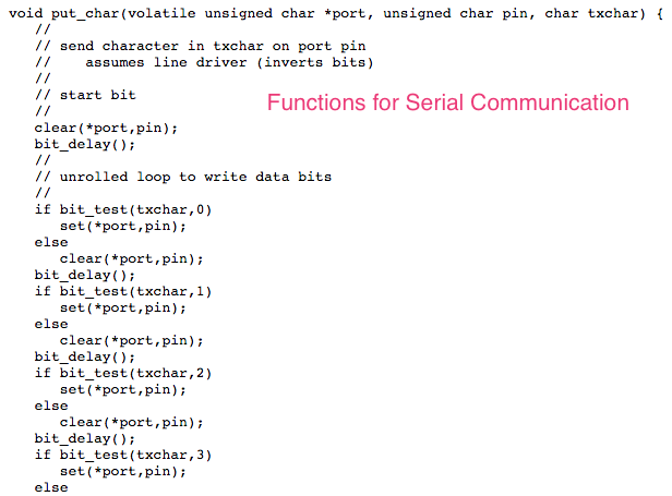
Of course Neil´s examples :
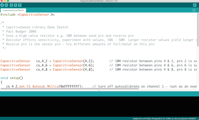
So i decided to focuss in to use the Arduino Library and made the first program there so i modified the example sketch made by Paul Badger. He made the Step Response example for 3 sensors and for the moment i use 2 . But obviously, not work, as my instructor tell me that the example never work with my board i confused with load again.
PROGRAMMING AND TESTING II : PROGRAMMING FOLLOWING NEIL EXAMPLE
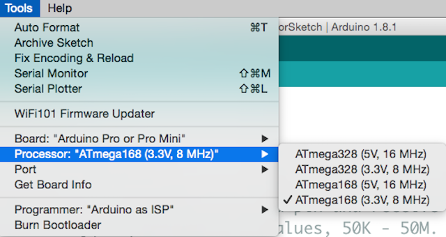
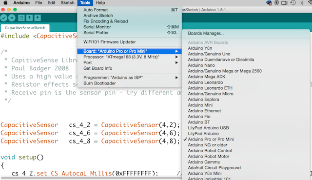
So i decided begin with neil example and modify somethings at Arduino IDE :
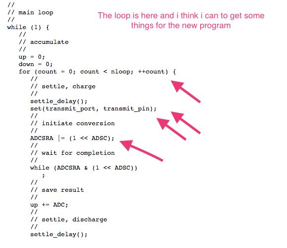
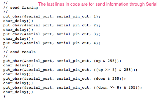
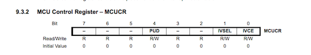
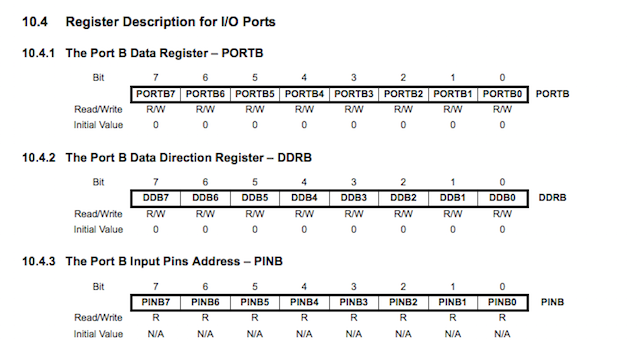
Later i went to the DataSheet again for recognize the pin ports that Neil mention in his program and extracted some usefull things from there was the moment make some questions more to my instructor so he suggested to me, take a look the page from my classmate Alvaro. He designed a board for his final project following the same steps, so together, we was taking a look to his program, understanding the final things for have something. Here are the codes i made with my instructor at arduino IDE.
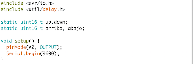
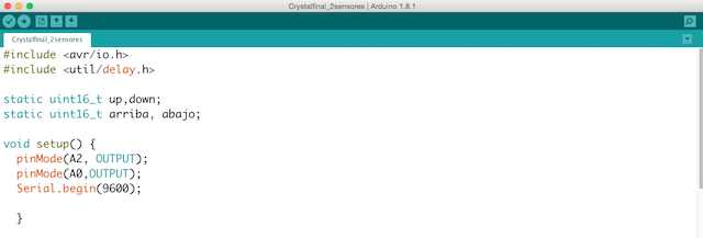
/* Pilu Caballero
FabAcademy 2017. Crystal Sensor Board.
Input Devices Assignment.
This code is based in Neil´ hello txrx.board and looked by my instructor suggestion at the page of my classmate Alvaro Fernández La Roja.
*/
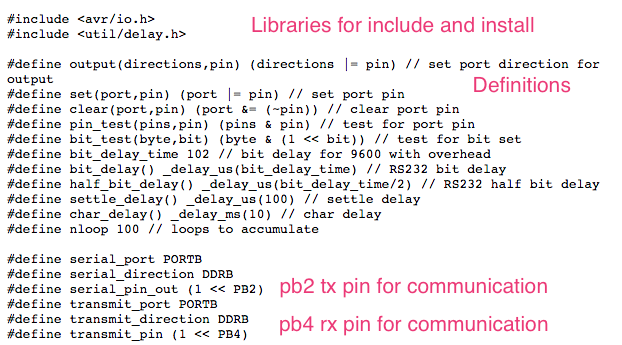
#include < avr/io.h>// Libraries previously installed
#include <util/delay.h>
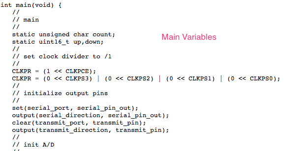
static uint16_t up,down; // extracted from Neil Program
static uint16_t arriba, abajo;
void setup() {
pinMode(A2, OUTPUT); // Declaring the first sensor pin out from my board
Serial.begin(9600); // Initialize Serial Communication
}
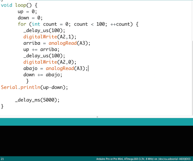
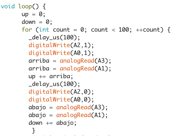
void loop() {
up = 0; // initial value for the states of sensor to up to 0
down = 0; // initial value to 0 for down
for (int count = 0; count < 100; ++count) {
_delay_us(100);
digitalWrite(A2,1); //the pin out and his state
arriba = analogRead(A3);
up += arriba;
_delay_us(100);
digitalWrite(A2,0);
abajo = analogRead(A3);
down += abajo;
}
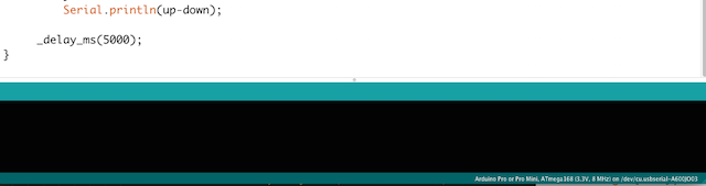
Serial.println(up-down); // messages for print at serial
_delay_ms(5000);
}
INPUT Devices : Programming with Arduino from Pilu Caballero on Vimeo.
As you see at the video looking at the values that appear on the video it seems that they are not increasing as they should when i touch the sensor. After this, i decided to try the second :
WEEK PROBLEMS
As i mentioned above, i had a problem designing my board, preparing my first hole file for mill are was solved.
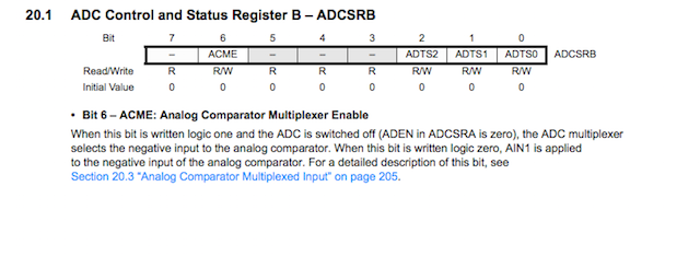
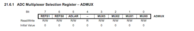
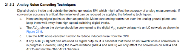
The other problem i had was understand all the DataSheet for example, with the registers or some things that i want to know for my final project but i solved asking to others.
The sensors didn´t work properly, are so experimental so their conductive properties are really variables.
THINGS I LEARNED
The sensors are an experiment for my personal studies so i don´t expect a lot but i learned that are analog so program them are really difficult.
I must to advance trying new programmes with other architectures.
WEEK CONCLUSIONS
Probably if i had to finnished the assignment in time i would to have more time for extend my conclusions about it.
Now i have a new way for an idea about an artistic installation which can turn real in future but should to be more researched until this.
Now i demostrate some ideas where meet some techniques and disciplines so fabacademy was a good point for begin.
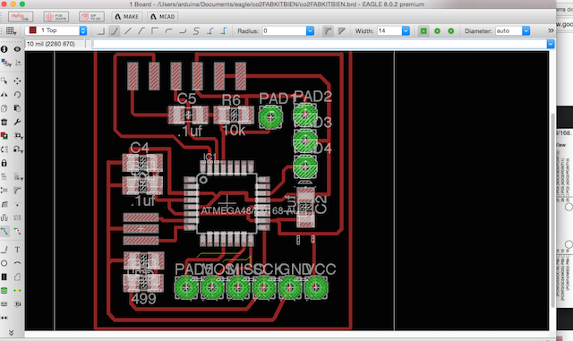
MY FINAL PROJECT INPUT
I decide begin with the practice for design my input sensor device board for my final project. I called it "Co2 Board" and the process i followed at eagle was the same explained in this weeks.Here is the result:

You can see about my main Input Sensor at my Final Project Process page here is the link :
Also i visited my friend´s atellier for begin with learning about How to sew the Kite:
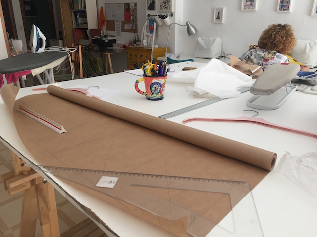
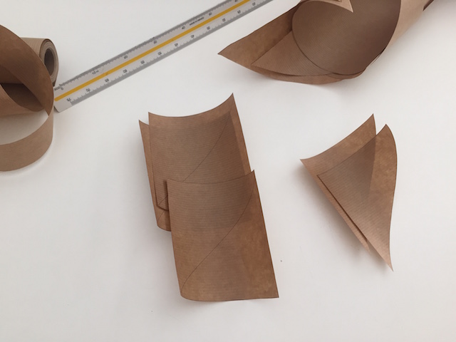
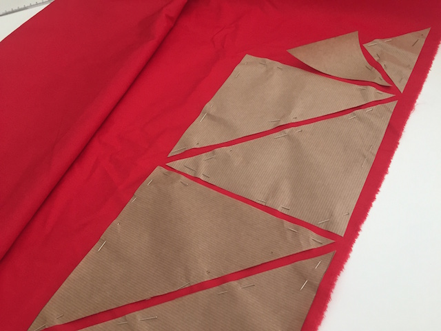
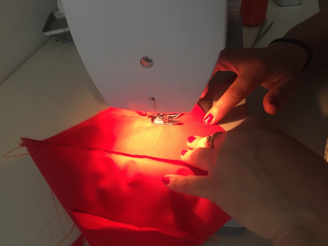
THIS LEARNED TO ME HOW TO DESIGN THE KITE CORRECTLY
But the most important thing, this task, made me to redesign the patterns thinking in how i should to assemble it. I was thinking in trianles always, but the design involve to sew squares. From here began the real patterns design.
WEEK FILES
GROUP PROJECTS
For this year we must to make some practices in group so Lucio and i decided to made basic testers with our boards.
How contribute for this task group? First of all i organize the works for to do in time, also develope the web site for this week explaining there all things worked together and individually.
Later made with Lucio the studio about the signal data coming from his board.
For finish i push all the conclusions.
So for see the experiments made together please visit our Group Project´s website here :