Thirteenth Week
INTERFACE AND APPLICATION PROGRAMMING
| HAVE YOU | TASK COMPLETED |
|---|---|
| Described your process using words/images/screenshots | YES |
| Explained the GUI that you made and how you did it | YES |
| Outlined problems and how you fixed them | YES |
| Included original code | YES |
NEIL´S LESSON
Index
- WEEK TASK : For the week´s assignment the goal is : * Write an application that interfaces with an input &/or output device that you made, comparing as many tool options as possible.
- The board Used
- References Followed
- Arduino to Processing Communications.
- Programming I : Serial Communication by Arduino
- Programming II : Arduino to Max with Serial Communication
- Programming III: Max/MSP GUI
- Programming IV: Max/MSP GUI : 3D Model Interactions.
- Programming v: Max/MSP GUI : Sound Interactions. Wind Effects
- Files
- My Week Problems Solved
- Things I Learned
- My Week Conclusions
This Week Assignment is for Write an application that interfaces with an input &/or output device that you made, comparing as many tool options as possible.
For this week assignment, i decided to use my Input Final project Board designed at Networking and Communications Assignment with the idea about to begin work with the CO2 an MQ135 sensor and learn more about it and the creative possibilities for make an interface for visualize first datas incoming from the sensor. The idea is connect the sensor with a Language that i´m learning from long time ago : Max/Msp - Jitter and interface with my students through this.
As i commented, the idea is communicate the CO2 sensor with other programs so with the board designed i decided to study some references first for understand the minimums required for teh assignment.
First i was reading was :
FROM ARDUINO IDE TO PROCESSING
As i have a bit experience with Processing, i decided to try communication from it. This Sensor came in a module and can to be use in 2 modes always as an INPUT : for Analog values and Digital Values. The idea is use the sensor with details so Analog Values are more interesting for me and for this assignment.
First i did was download Processing from his Official Wbsite where i found some interesting links for learn :
Download Processing
Getting Started
Serial Communication
PROCESSING
Processing ControlP5 example 1: user interface
The controlP5 library for Processing makes it easy to add knobs and buttons to your Processing applications.Here an example how to add some interface elements (buttons, sliders etc.) and how to listen to their events.
ControlP5 is a GUI and controller library for Processing. You can easy add controllers to your program. You can download the ControlP5 library at the site of Andreas Schlegel.
After downloading und unpacking you can copy the library in the ‘libraries’ subfolder of the Processing sketches folder.
The library comes with a lot of examples, but it lacks a bit an overview how to use different elements together. In this example an overview of some basic GUI elements and how you can handle their events.
See the sketch in action at openprocessing.org. Download the zip-file ( with all the examples ) : controlP5-examples.zip
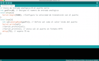
1. Firs i made was write some lines of code at Arduino :
// Send analog input to the serial port

int gasPin=A0; // Designa el numero de entrada analógica
void setup(){
  Serial.begin(9600); // Speed baudrate
}
void loop(){
  int val=analogRead(gasPin); // Define val as the value read by the port
  Serial.write(val);
  //Serial.println(val);
  //Serial.println(); // envía val al puerto en formato BYTE
  delay(75); // wait  75 ms
}
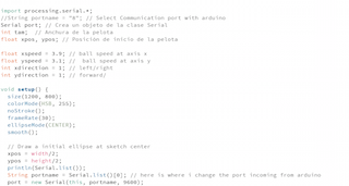
2. Later in Processing : I modiffied an application for interfacing with Arduino trought serial port founded in Processing examples :
SerialBounce
import processing.serial.*;
Serial port; // Crea un objeto de la clase Serial
int tam; // Anchura de la pelota
float xpos, ypos; // Posición de inicio de la pelota
float xspeed = 3.9;
float yspeed = 3.1;
int xdirection = 1;
int ydirection = 1;
void setup() {
size(720, 640);
colorMode(HSB, 255);
noStroke();
frameRate(30);
ellipseMode(CENTER);
smooth();
xpos = width/2;
ypos = height/2;
println(Serial.list());
String portname = Serial.list()[2];
port = new Serial(this, portname, 9600);
}
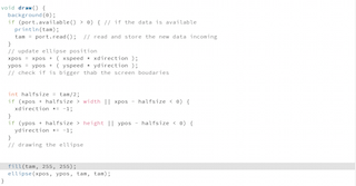
void draw() {
background(0);
if (port.available() > 0) {
println(tam);
tam = port.read();
}
xpos = xpos + ( xspeed * xdirection );
ypos = ypos + ( yspeed * ydirection );
int halfsize = tam/2;
if (xpos + halfsize > width || xpos - halfsize < 0) {
xdirection *= -1;
}
if (ypos + halfsize > height || ypos - halfsize < 0) {
ydirection *= -1;
}
fill(tam, 255, 255);
ellipse(xpos, ypos, tam, tam);
}
Interface and Applications : Processing from Pilu Caballero on Vimeo.
Serial Communication by Arduino
Embedded electronics is all about interlinking circuits (processors or other integrated circuits) to create a symbiotic system. In order for those individual circuits to swap their information, they must share a common communication protocol. Hundreds of communication protocols have been defined to achieve this data exchange, and, in general, each can be separated into one of two categories: parallel or serial.
Serial communication on pins TX/RX uses TTL logic levels (5V or 3.3V depending on the board). Don't connect these pins directly to an RS232 serial port; they operate at +/- 12V and can damage your board.
Serial is used for communication between the Arduino board and a computer or other devices. All Arduino boards have at least one serial port (also known as a UART or USART): Serial. It communicates on digital pins 0 (RX) and 1 (TX) as well as with the computer via USB. Thus, if you use these functions, you cannot also use pins 0 and 1 for digital input or output. You can use the Arduino environment's built-in serial monitor to communicate with an Arduino board. Click the serial monitor button in the toolbar and select the same baud rate used in the call to begin()
Arduino and Genuino boards have built in support for serial communication on pins 0 and 1, but what if you need more serial ports? The SoftwareSerial Library has been developed to allow serial communication to take place on the other digital pins of your boards, using software to replicate the functionality of the hardwired RX and TX lines. This can be extremely helpful when the need arises to communicate with two serial enabled devices, or to talk with just one device while leaving the main serial port open for debugging purpose.
In the example below, digital pins 10 and 11 on your Arduino or Genuino boards are used as virtual RX and TX serial lines. The virtual RX pin is set up to listen for anything coming in on via the main serial line, and to then echo that data out the virtual TX line. Conversely, anything received on the virtual RX is sent out over the hardware TX.
So this is the code i modified for begin : As you can see i changed the TX /RX 10 and 11 by 0 and 1 adding a message for indicate the sensor is ready for work readable with the monitor serial, also i changed the baudrate by 9600bau.
/*
  Software serial multple serial test

 Receives from the hardware serial, sends to software serial.
 Receives from software serial, sends to hardware serial.

 The circuit:
 * RX is digital pin 10 (connect to TX of other device)
 * TX is digital pin 11 (connect to RX of other device)

 Note:
 Not all pins on the Mega and Mega 2560 support change interrupts,
 so only the following can be used for RX:
 10, 11, 12, 13, 50, 51, 52, 53, 62, 63, 64, 65, 66, 67, 68, 69

 Not all pins on the Leonardo and Micro support change interrupts,
 so only the following can be used for RX:
 8, 9, 10, 11, 14 (MISO), 15 (SCK), 16 (MOSI).

 created back in the mists of time
 modified 25 May 2012
 by Tom Igoe
 based on Mikal Hart's example

 This example code is in the public domain.
 Modiffied by Pilu Caballero for test Sensor Board */


#include <SoftwareSerial.h>

SoftwareSerial mySerial(0, 1); // RX, TX

void setup() {
  // Open serial communications and wait for port to open:
  Serial.begin(9600);
  while (!Serial) {
    ; // wait for serial port to connect. Needed for native USB port only
  }


  Serial.println("Pollution DetectoR!");

  // set the data rate for the SoftwareSerial port
  mySerial.begin(9600);
  mySerial.println("Hello, world?");
}

void loop() { // run over and over
  if (mySerial.available()) {
  Serial.write(mySerial.read());
  }
  if (Serial.available()) {
    mySerial.write(Serial.read());
  }
}
When uploaded the example to the board worked fine so i´m ready for communicate with other languages.
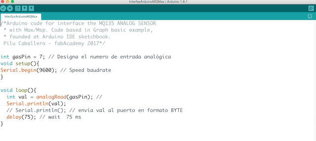
FROM ARDUINO TO MAX/MSP-JITTER BY SERIAL
I decided begin with this example, modifying some things such as the serial port and the baudrate for my CO2 Board based in the FabKit to 9600 and uploaded the program to my board before to open with Max/Msp-Jitter :
const int gasPin = 7;    // Pin where is attached my sensor

void setup() {
  Serial.begin(9600);
}

void loop() {
  int val = analogRead(gasPin);
  Serial.print(val);
  Serial.println(val);
  delay(75);

}
Sometimes, I used Max/Msp Jitter for code generative visuals so i decided began with simple interfacing throught serial there. Max/msp is a great tool from Cycling 74 which is growing in the last years a lot turning the application friendly for new users, famous for his capabilities about Hardware and software communications trought differents protocols sucha as OSC, UPD, Serial, MIDI...
You can learn more about the tool at his Official Website :
When beginning my quest to get Arduino and Max talking to each other, the first and most useful place to start looking was on the Arduino Playground website. Here it lists several methods, Max patches, and Arduino code that enable communication between Arduino and Max, with some being a lot more useful than others.
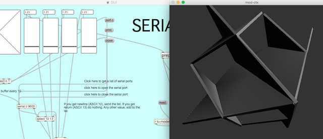
At Max i can communicate my boards with diferents ways but i´m working on serial so i decided wrote a basic application with a GUI which receive the sensor values and move some sliders for control de output range and send values to Outputs devices.
There you can find an object called Serial with a helpfull reference for begin :

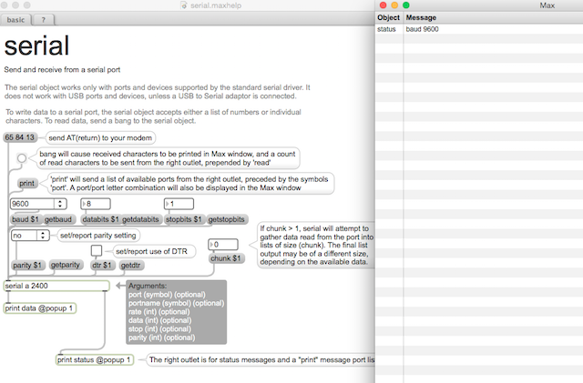
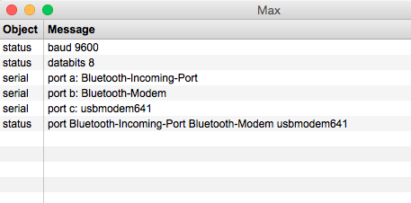
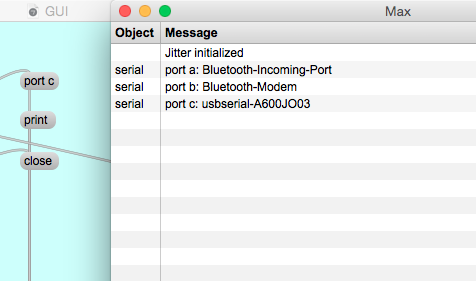
1. First i did was identify the ports where my board is connected pressing message object at the example and showing the Max Console : Now i know my port is c:
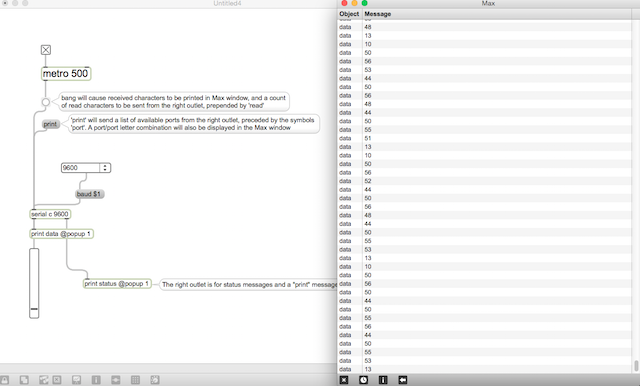
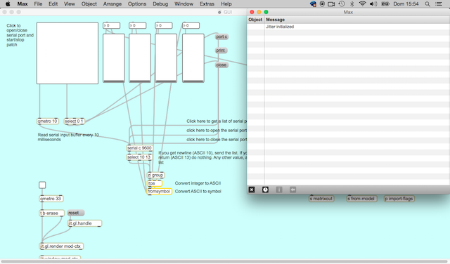
2. Later i put some objects for made the first patch :
Here is a video where you can see the sensor connected with max/msp-jitter :
Gas Data Sensor from Pilu Caballero on Vimeo.
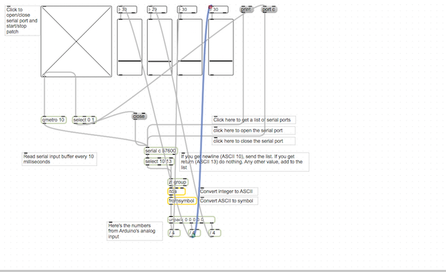
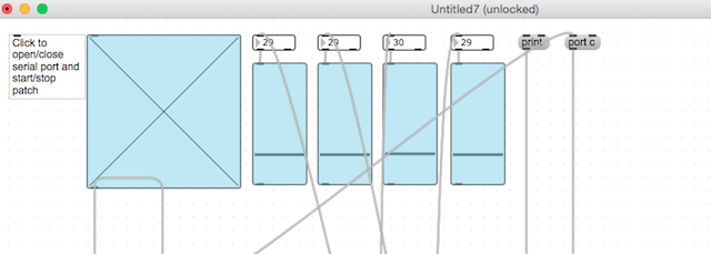
3. I added 4 slider for representing my Leds Outputs. Each is slider is connected to the Analog Input Values Received. Also I was commented each thing for clear in future, i made some videos during programming time for made better understable the simply process for made a basic GUI:
SERIAL PATCHES from Pilu Caballero on Vimeo.
MAX INTERFACING from Pilu Caballero on Vimeo.
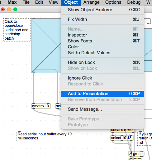
4. For finish with the first part with the GUI i prepared some things for a prototype purpose, this process at max is really easy, just selecting each object you want and add to presentation:
5. As yo can see at the picture, i decided use the sliders, the Toogle for activate the application, the message with port appropiated for my board and the number object box, for visualize the Gas Values received.
MAX INTERFACING AND APPLICATION from Pilu Caballero on Vimeo.
SERIAL_FINAL from Pilu Caballero on Vimeo.
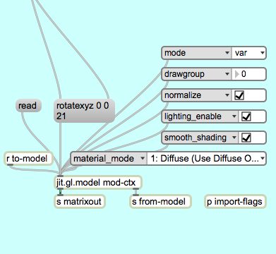
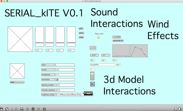
The last things i was trying was design some interactions inside the basic GUI. The idea is made the CO2 sensor interactive with sounds and 3D possible models.
Programming IV: Max/MSP GUI : 3D Model Interactions.
Interface and Application : Arduino to Max/msp with MQ 135 sensor from Pilu Caballero on Vimeo.
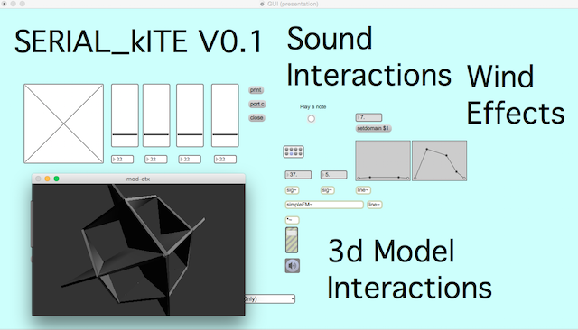
Interface and Applications : GUI interactions with 3D Models from Pilu Caballero on Vimeo.
Programming V: Max/MSP GUI : Sound Interactions. Wind Effects.
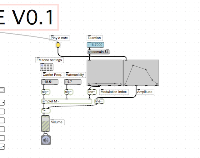
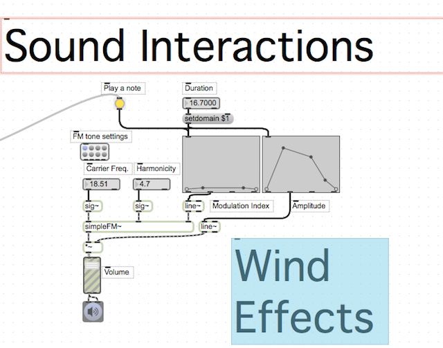
Interface and Applications : GUI interactions with Sounds Effects from Pilu Caballero on Vimeo.
COMMUNICATIONS PROTOCOLS : OSC
If you’re not familiar with OSC, it is a protocol for communication among computers, sound synthesizers, and other multimedia devices that is optimized for modern networking technology. It can be seen as an alternative and updated version of the MIDI protocol, which has shown prominent limitations in recent years. After initially getting my head around it, I found OSC to be very simple to use and understand, and it can be implemented in Max by downloading the Max externals at CMAT :
OSC is starting to become a well-known protocol, so I thought it would be worth using in the assignment.
The source code for is an Arduino and Teensy library implementation of the OSC (Open Sound Control) encoding.It was developed primarily by Yotam Mann and Adrian Freed at CNMAT where OSC was invented. It benefits from contributions from John MacCallum, Matt Wright, Jeff Lubow and Andy Schmeder and many beta testers.
Features:
Installation
The CNMAT recommend Arduino 1.05 or greater and Teensyduino 1.14 or later if you use the Teensy. Download the zip from github. Unzip it and remove text after the "-" in the name (i.e. -master) because the Arduino IDE doesn't allow certain characters in library names. Move the OSC folder into your "libraries" folder in your Arduino Sketch search path. Now you will see OSC examples under the Examples menu of Arduino.
Examples
The Applications folder contains examples for Max/MSP and PD and Processing that work with the example sketches. This will be expanded to include other applications like TouchOSC and Processing. For the Max/MSP examples you will need to download the CNMAT max externals package that includes the "o." objects available.
One way to communicate with OSC protocol my board with Max is using Maxuino. Here are a serie of videos for learn how to use it :
Getting Started with Maxuino Part 1: Installing Firmata from Chris Coleman on Vimeo.
Getting Started with Maxuino Part 2: Installing Maxuino from Chris Coleman on Vimeo.
Getting Started with Maxuino Part 3: Using Maxuino from Chris Coleman on Vimeo.
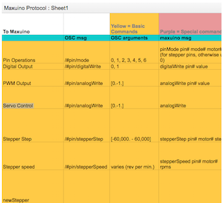
For understand better how works Maxuino, here you will find a list of commands and what they do:
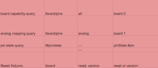
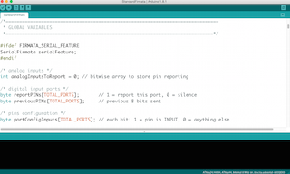
1. So for communicate arduino with Max throught Maxuino first i made was upload to my board the Arduino Standard Firmata example.
a)Connect USB cable to the board and your computer.
b)Start Arduino software.
c)Select your board from Tools -> Board
d)Select your Serial connection from Tools -> Serial Port
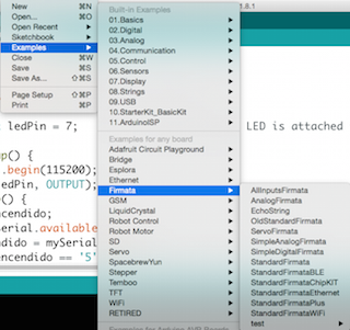
e)Open the Firmata program by going to File -> Examples -> Firmata -> StandardFirmata
f)Upload the Firmata program to my board by pressing the upload button or File -> Upload
e)When the upload is finished i closed the arduino software.
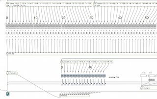
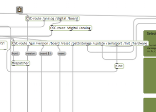
2. Later y opened MAXUINO maxpat and maxuino maxhelp.pat :
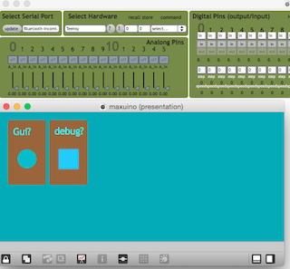
a) The patch is designed to help introduce the user to the multiple ways of communicating with Maxuino. Maxuino is made of two major parts: the Maxuino GUI and the maxuino.maxpat. The GUI is a easy to use interface that is M4L compatible and also an OSC translator. The maxuino.maxpat translates Max commands into Firmata commands and sends them out of the serial port and translates the other way when incoming messages are received.
b) Using the upper right box, selected the serial port for my board 9600.
c)Next i need to set the modes for each of the pins i will use. The easiest way is to use the GUI. Ad it is not open, pressed the /gui message button in the middle left of the patch. You will see that you can also select the serial port from here as well as select the particular board you are using. Choosing a board will grey out pins and options that are not available for that board. There are also options to save and load a pin setup. The analog inputs are on the left (and can be turned on or off), and the digital pins are on the right and have 7 modes: Digital inputs,Digital output, analog inputs,PWM output
d)Once a pin mode is chosen, either the input information will begin to show up or i can use the various controls to manages my inputs.
Selecting the appropiate board i can check how the analog data incoming from the sensor is not working, here was the 2nd problem i noticed so you can go to week problems section for know more about it.

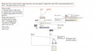
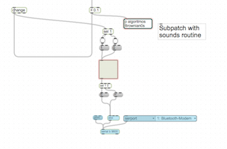
Thinking on my Final Project, i decided to make a patch adding sounds and led blinking so for that i implemented OSC with Maxuino GUI and adding a subpatch with sound routine that interact with leds too :
WEEK PROBLEMS
This week the problem i had was trying to use OSC protocols with Arduino and Max but my board is based in the FabKit with the 168P as micro-processor so i discovered some things :
1. The memory of my processor is too tiny for use the StandardFirmata Example necessary for upload to my board before communicate with maxuino GUI.
2. Maxuino GUI didn´t recognized my board.
3. For use OSC is better send the incoming values following the old method suggested at Arduino Official Website.
THINGS I LEARNED
This week i learn a lot about interface with arduino, processing and max/msp but i should to practice more but was impossible with my actually job.