
|
| Sukkur IBA University Merit, Quality, Excellence |
FINAL PROJECT
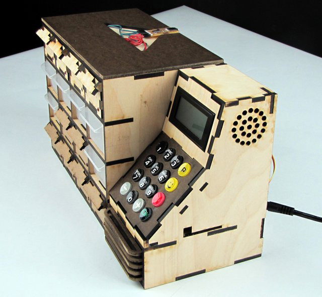
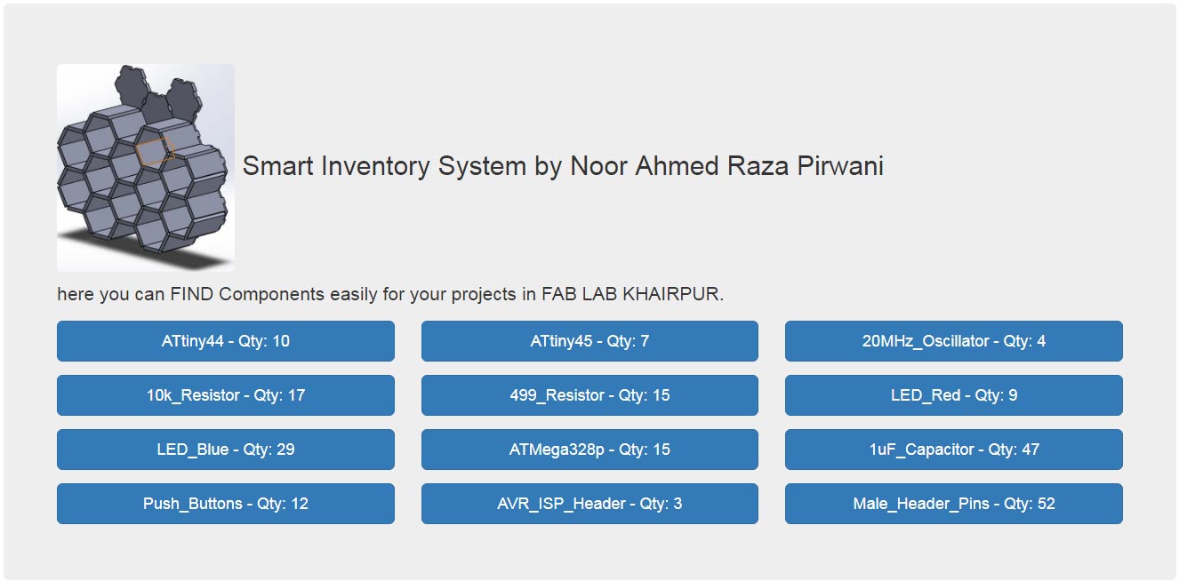
Smart Inventory System for Small Components
Summary Slide of Final Project:
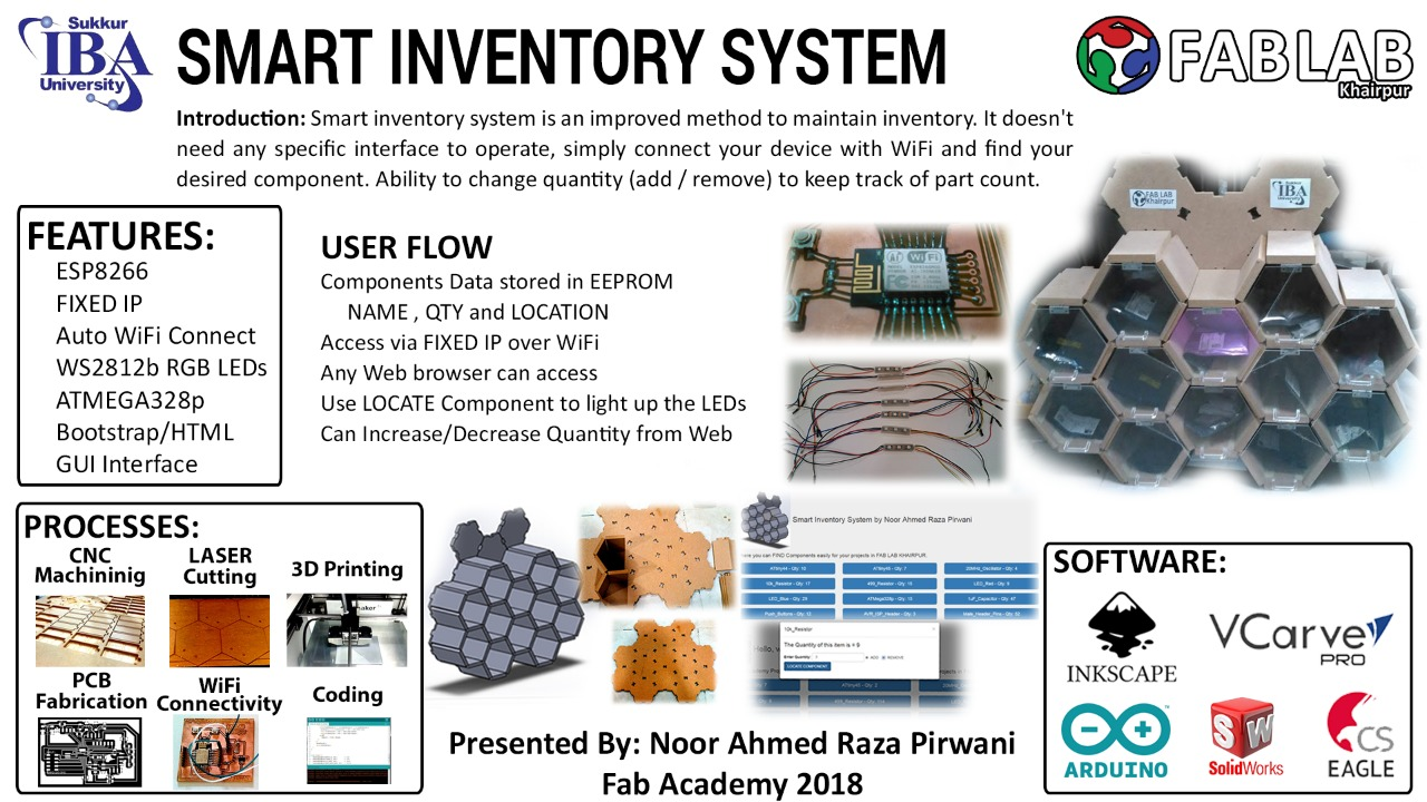
slide presentation.png
Final Project Video
Problem Statement:
Proper placement of components, make them categorize and keep inventory update is the difficult task, it is the process which is better to be done when changes occur. Doing inventory was a difficult part of my previous job as Space Manager in TajurbaGah. To place small components we have cabinets with boxes, which are categorize and updated on excel sheets. But whenever someone needs any component from those boxes it takes time to find. As for my final project I want to solve that problem by making a smart inventory system which indicates the shelves in which desired components are present.
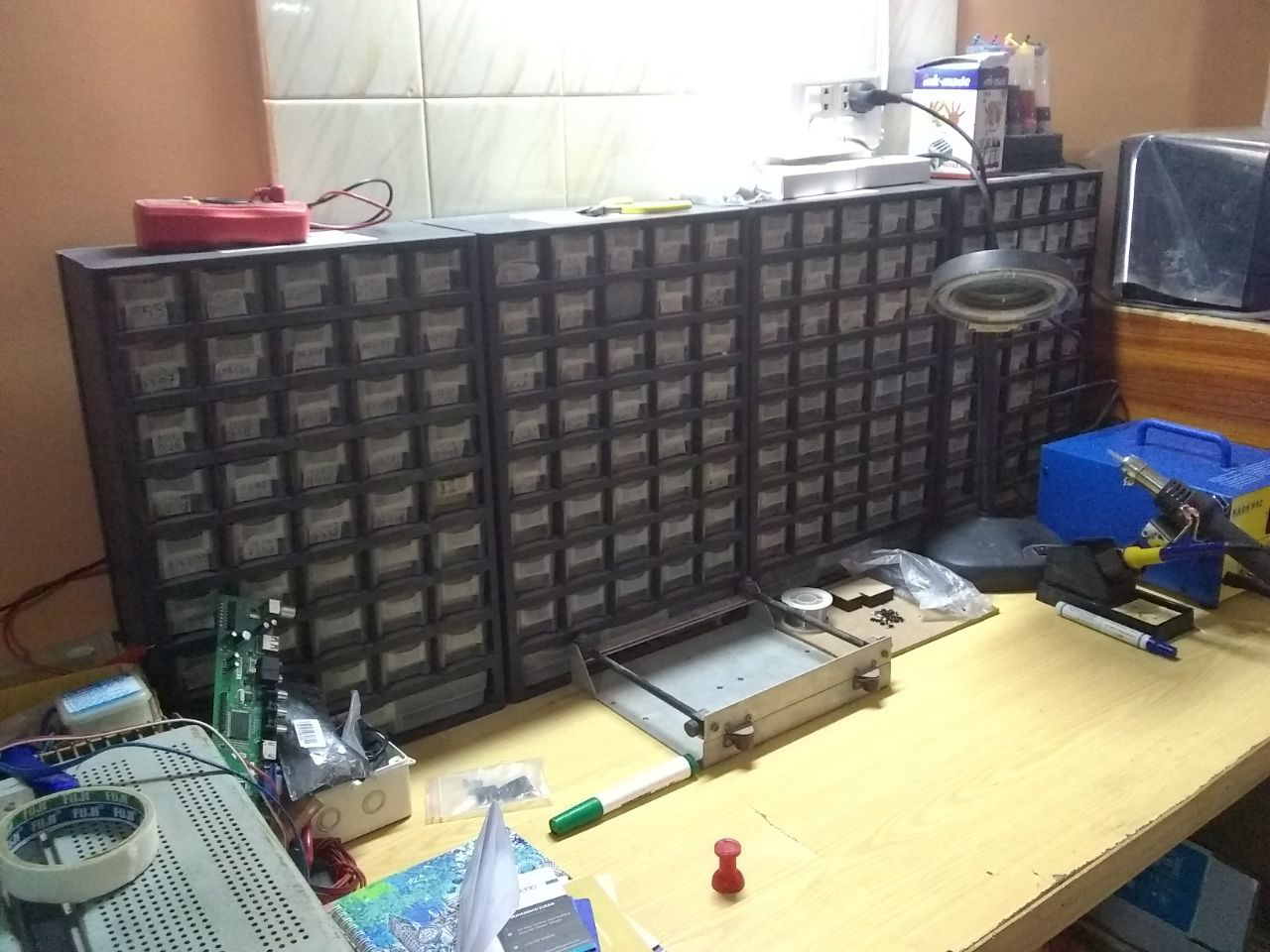
Electronic components placement at MAKERSPACE Tajurbagah Karachi
Ideation Phase:
To maintain inventory and to keep record about the presence of specific component and their no. of quanity some kind of mechanism is required. My idea for the final project is to make a shelf in which different components are present in boxes and when someone need any component it indicates that box and then update the present quantity in the inventory.
2D Raster sketch of my final project Idea
After discussion with my local and regional instructors about my final project. They point out that to make this idea as my final project I need to mention why my project is different from existing inventory projects. They shared some past students webpages which already propose ways to solve this problem as comparision of my project with them problem statement is same but method to solve the problem is different I am sharing inventory projects below and then I describe in another section about my project
First Project: Inventory Bot
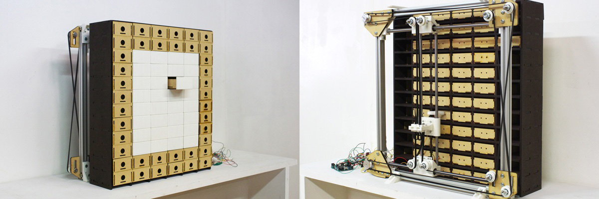
Inventroy Bot Front and Back View
Here is the link of this project page. This project is made by Kohei Morimoto from FABLAB Kitakagaya Japan in 2017. The mechanism is based on core XY sytem which is made and attached on back of the cabinet a shaft with servo motor is attached on the head which pushes out the desired drawer, when a person need any component he/she has to give two inputs to machine a name of component and no. of quantity after that if the component is available the core XZ system move toward that box and push it out. The arduino is used to control the core XZ system which gets instruction from PC and act according to it.
Second Project: Wally
A look to Wally
Here is the link of this project page. This project is made by Kenzo Prada Abiko from AS220 FabAcademy in 2015. This project also designed to maintain the inventory for the specific projects. To interface with machine, LCD is placed alongside buttons which are also fabricated, a person needs to input a number of project and the boxes which have component of those project light up to mention. After taking desired component a person need to enter the number of component he/she tooks. and inventory updated with respect to it.
Planning Phase (Ver.2):
Everything is going as planned then suddenly I met this guy: Mr. Francisco Sanchez. He visited Pakistan as per request of our instructors to repair ShopBot. We learn many things from him, he also gave us ideas about projects and modified our final projects ideas to be more better.
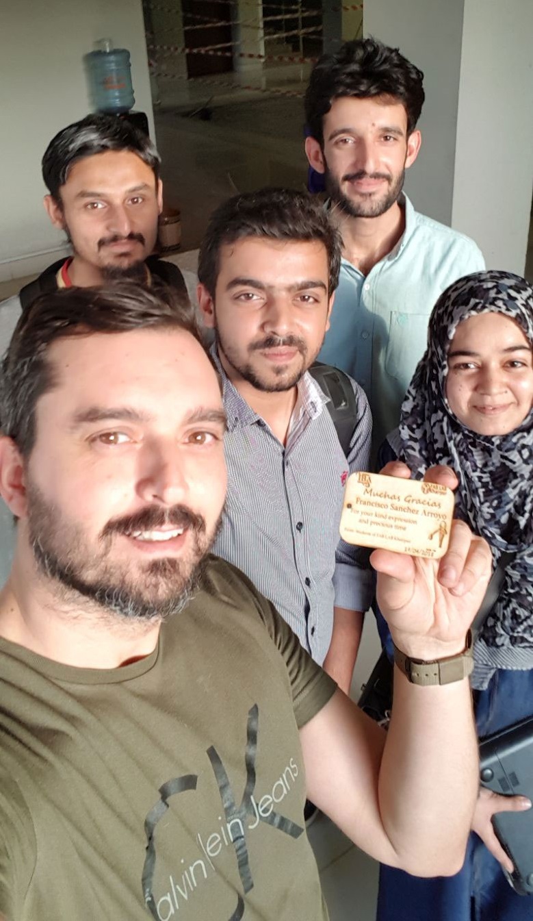
Group Selfie with Mr. Francisco
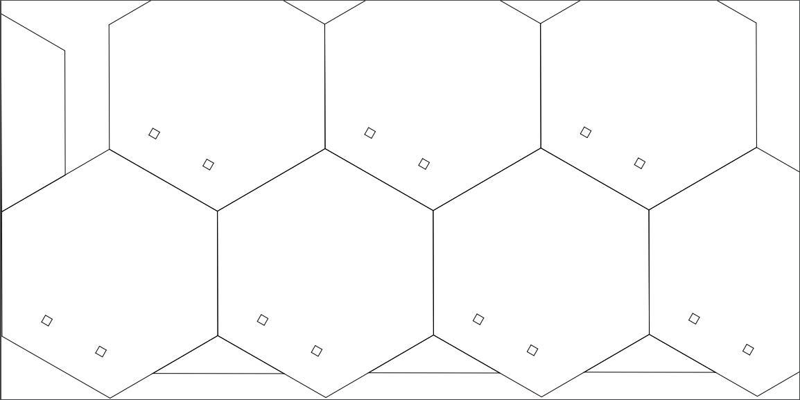
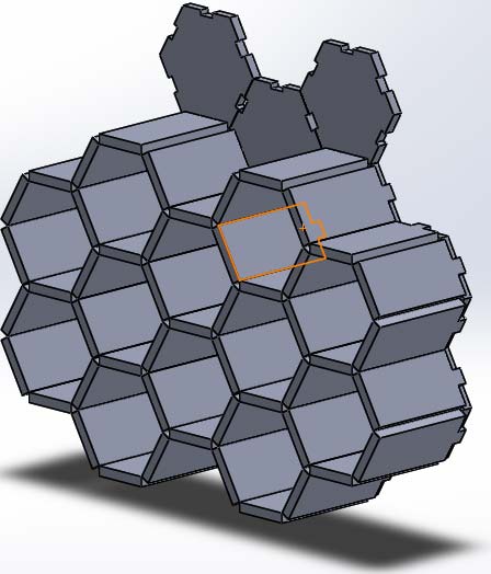
Here is the link to visit my project plannig (ver.1) of final project. For Ver.2, I am sharing a simple sketch which is become the base for honey comb structure shelves in my final project. The below sketch shows some fix IP where search box is present along with shelves on screen to indicate the desired component.
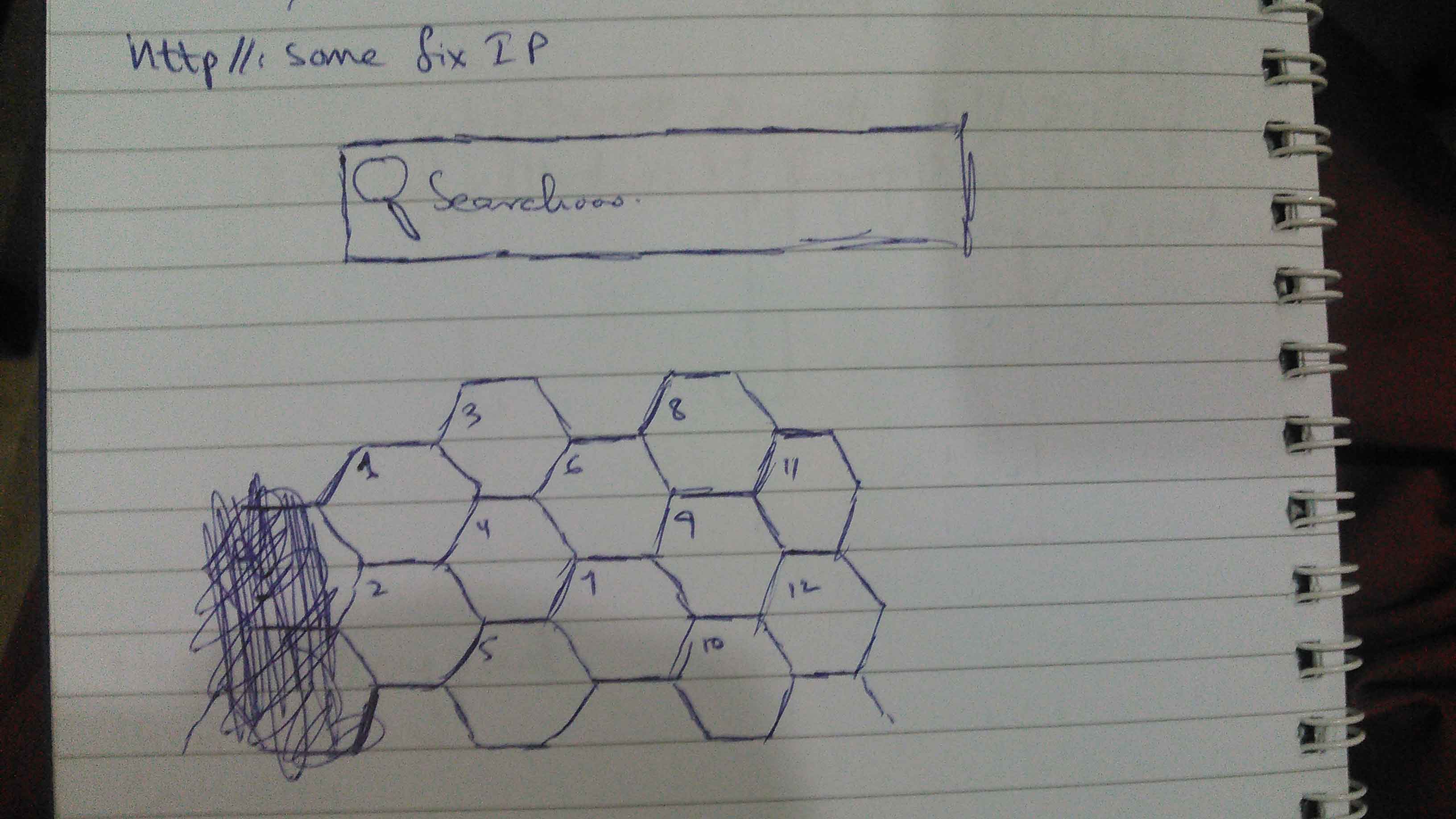
Project Sketch
User Journey:
A user journey represents a sequence of events or experiences a user might encounter while using a product or service. Here I am presenting a user journey to understand systematic flow of whole system.
- First a user asked for IP address from any of lab representator which is fixed by programmer for ESP-12E to operate the inventory system.
- User input the IP address in the browser of his/her laptop or mobile phone
- IP address opens the page in which a user found the list of items along with the no. of quantity which is stored in EEPROM of ESP-12E.
- When user click on his/her desired item in the list a pop-up appears to ask the no. of quantity either to remove or add in the shelf. and a button to locate item in inventory
- A user after adding no. of quantity and checked either remove or add, they press "locate component" button. With this ESP-12E pass a signal to 328p board to blink RGB LEDs of a specif box in which desired component/item is present
Implementation Phase (Ver.2):
After generating idea, we planned a sketch. Now It is time to work as per plan, to describe implementation I split my project documentation into two main parts which are:
- Mechanical Structure
- Electronic System
Mechanical Structure
Making of Main Structure
I assume a giant honeycomb structure in which instead of honey we put components in bulk, so user can find the desired component easily and update the quantity of specific components in database while finding them.
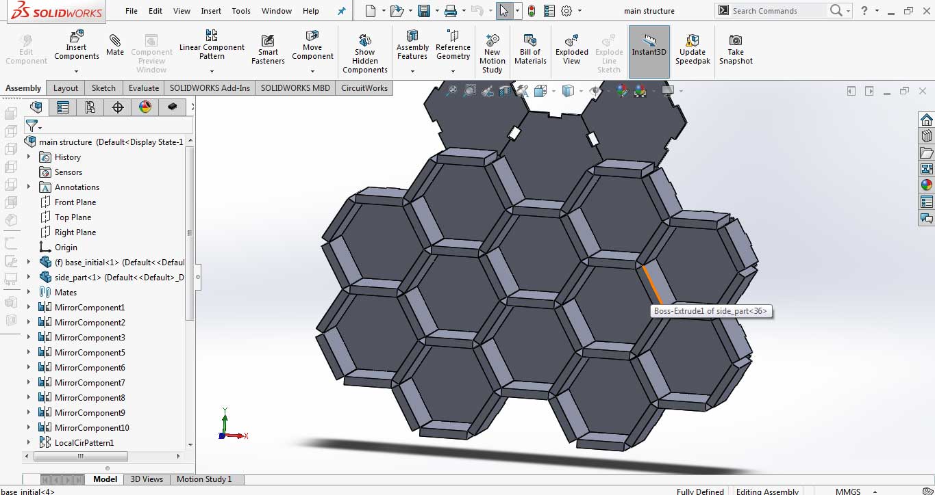
To talk about 3D modeling or designing only one software came in my mind, as I have whole FAB Course experience to work on SolidWorks, thats why I choose this software for making 3D model of honeycomb structure. In Solidworks we split the design into parts, seperately made them and then assemble them togther to complete the 3D model. In this case we make two parts, base and wall.
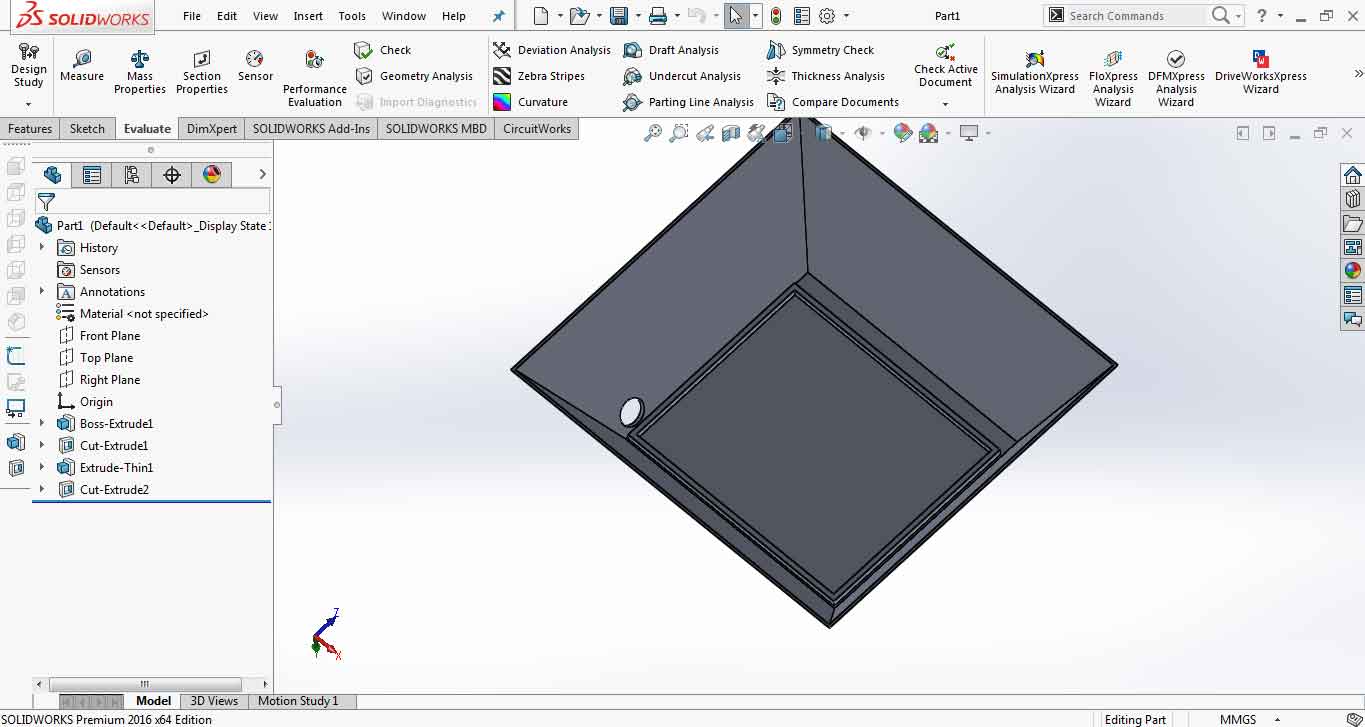
Making of Base
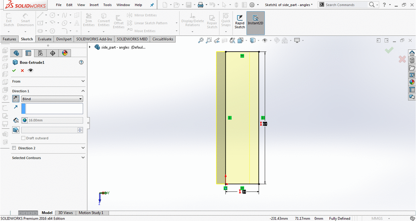
To make a base, first we made a sketch of shape with 6 sides(hexagon), sketch it and extrude it to thickness of wood "16mm".Then we made a 25mm box in center of one side and use "linear component pattern" to cpy it all 6 sides. After that I extrude cut those 25 mm boxes. and the base of singal shelf is made.
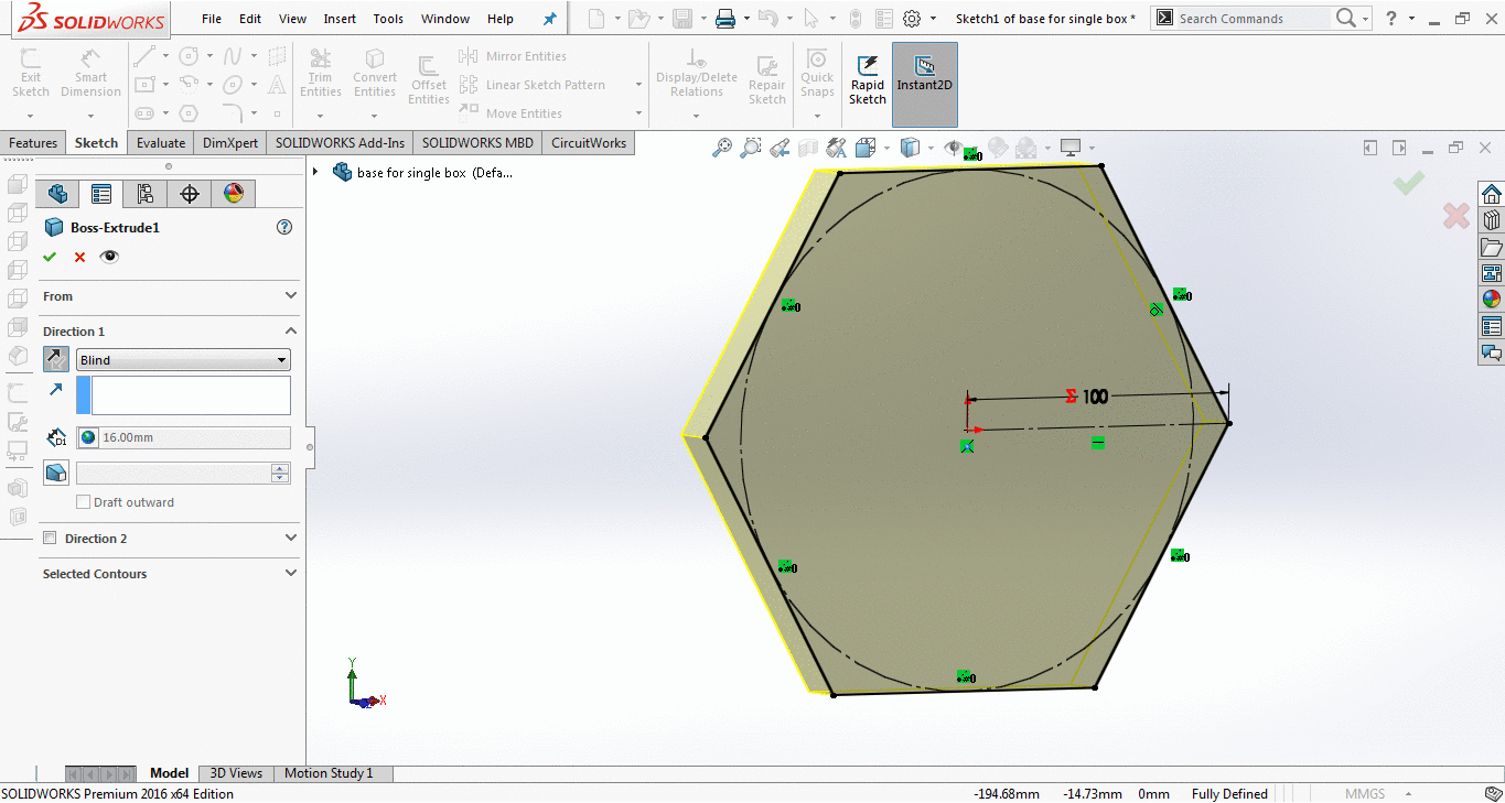
Base for singal shelf
Then in assembly document of solidworks using Mirror, I mirrored it to several times to make whole base structure.
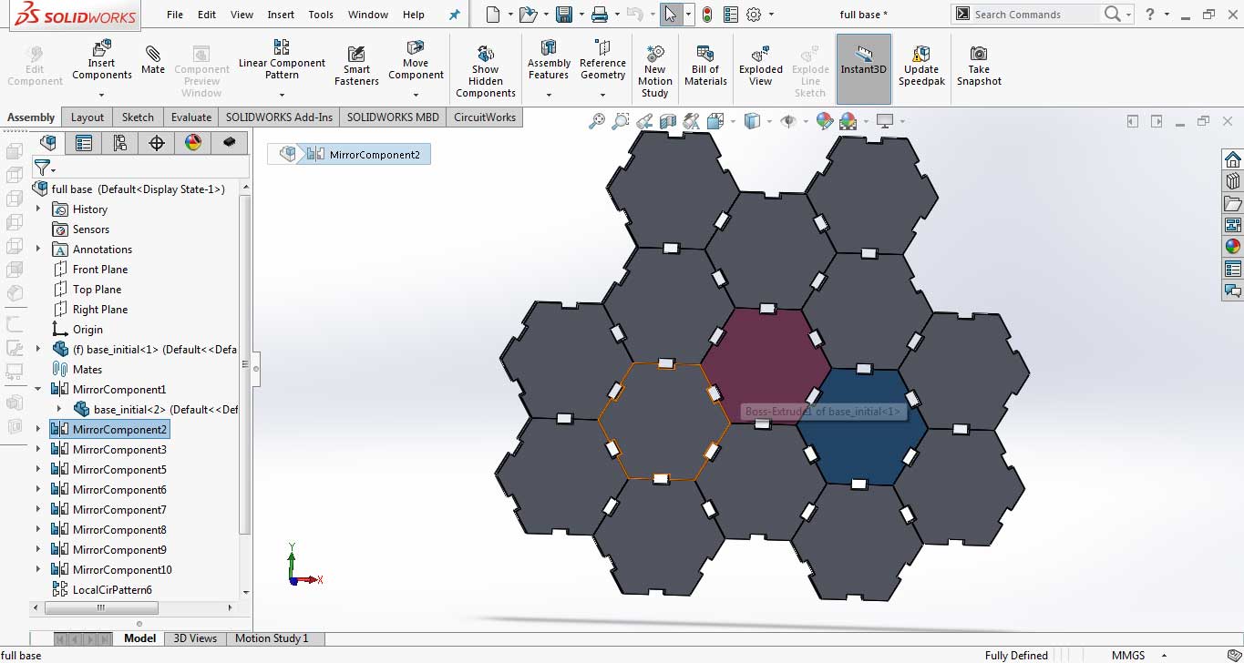
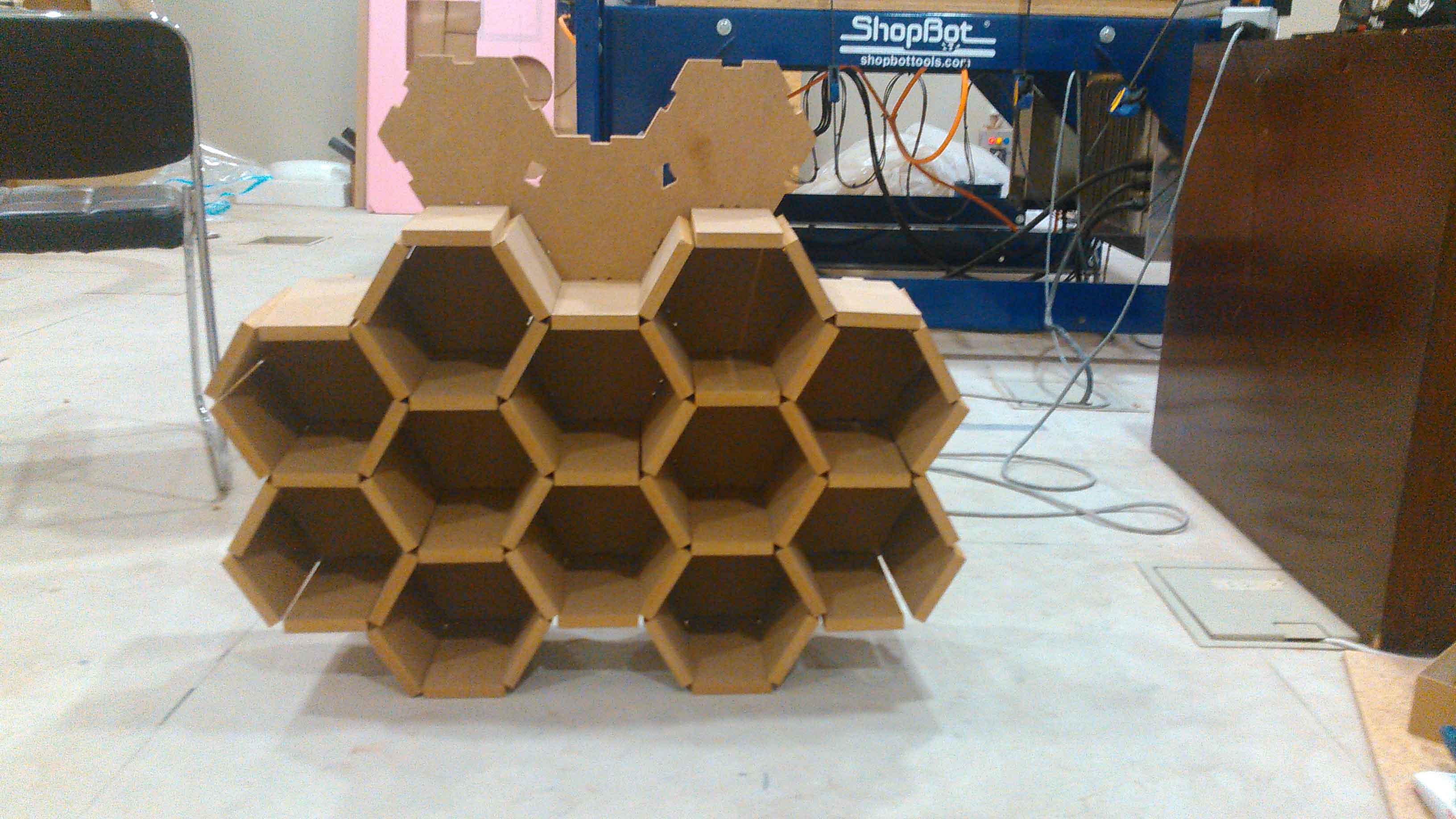
Whole Base
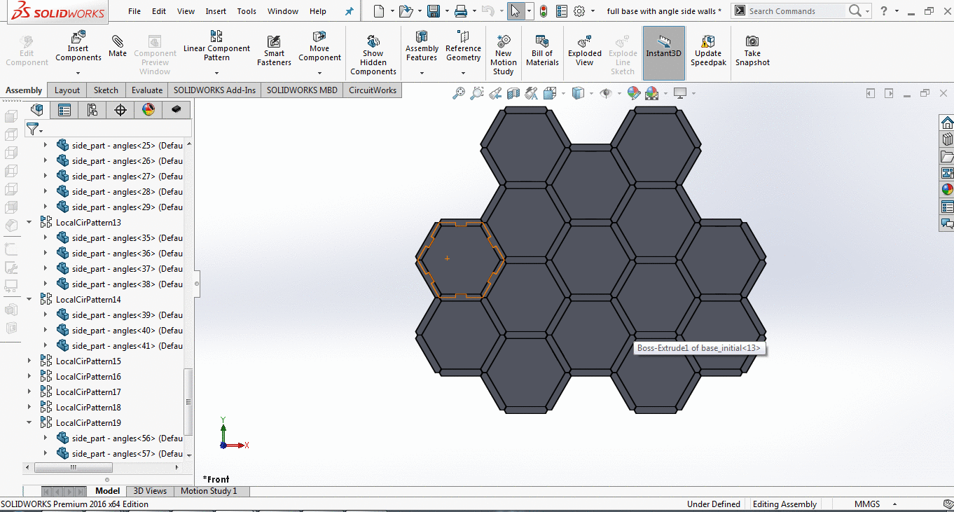
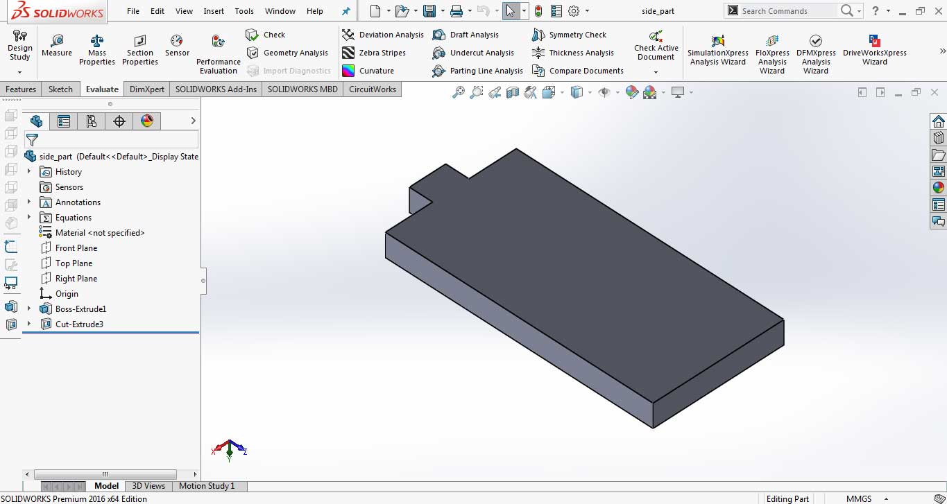
Making of Side Wall
To make a side wall, first we made a sketch and extrude it to thickness of wood "16mm".Then on edge I made a rectaangles using lines and mirror and then extrude them to fix the side wall in base. To connect iwth other walls I made slopes on either side of side wall tso they fix with other wall by supporting them also.
Side wall
Side wall (with slopes) fixing more perfectly then the other original design.
Unfortunately there is a less time for me to learn how to cut slope on both side in Shopbot (obviously there is a way to cut one side then to set the wood again on a same place to cut it from backside). I remake the side wall with simple sides by decreasing the width from 100mm to 90. It leaves the triangle like hole between hexagons when assemble it.
Side wall (without slopes).
Side wall (without slopes) setted up on base.
Joining Base and Side Walls:
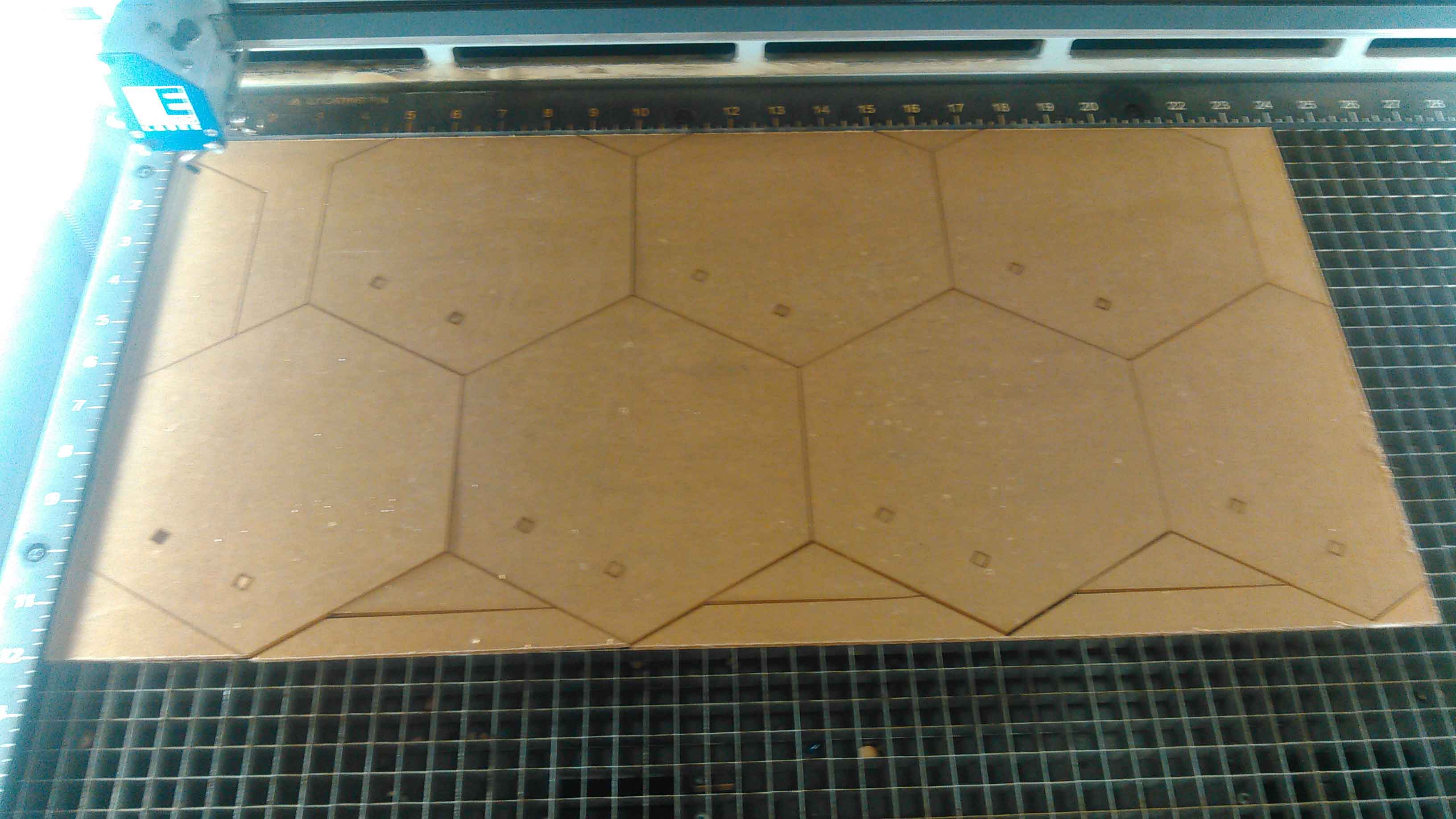
After generating toolpath from VCarve I cut them both using Shopbot. To learn how to generate toolpath from VCarve please visit Generate toolpath
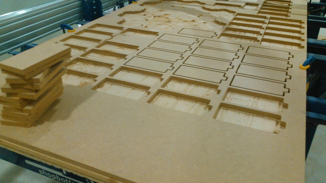
Cutted Parts from Shopbot.
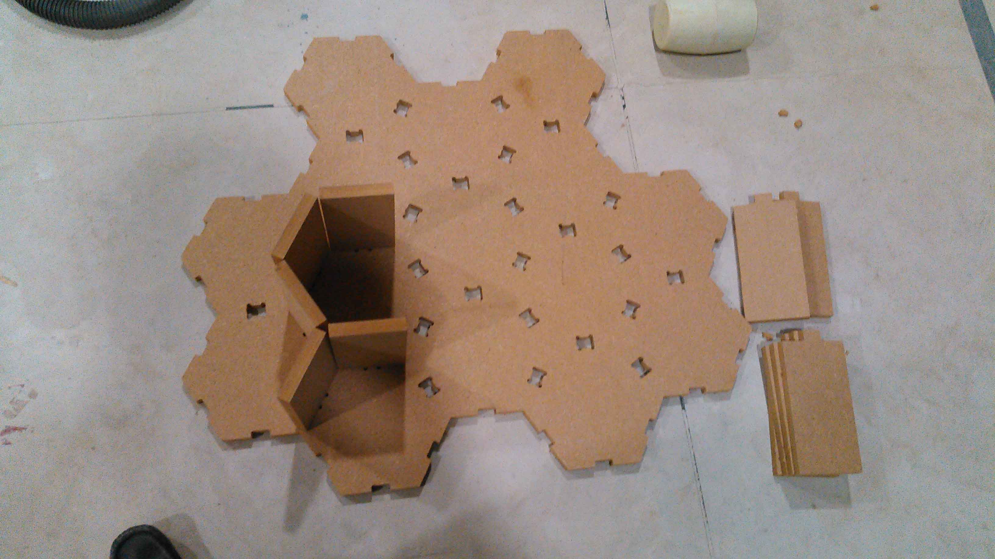
Joining side walls on base.
The Result is pretty expected.
Making Doors for Shelves
I have two options here: either making doors or making box for shelves, because of the size and hexagonal shape I decided to go with doors. For making doors I selected 3mm acrylic sheets to for laser cutting to get doors. But we have very limited 3mm Acrylic sheets in our lab and one of my colleague also want to use them. It takes 4 sheets to make perfect 12 boxes, in which most of the acrylic become wastage, so I scaled my utilization of acrylic sheets of 2x1 ft from 4 to only 2. I cut some doors in 2 parts and then use Elfy glue to join them.
The doors are first made in Solidworks along with handles then change to .dxf to open in inkscape file. From inkscape it changes to .dxf to .svg. And after changing in svg file it converts to .pdf format for laser cutting process (all files are attached in this week files).
fixing 7 doors in one 1x2 ft sheet.
doors while cutting in laser cutting machine.
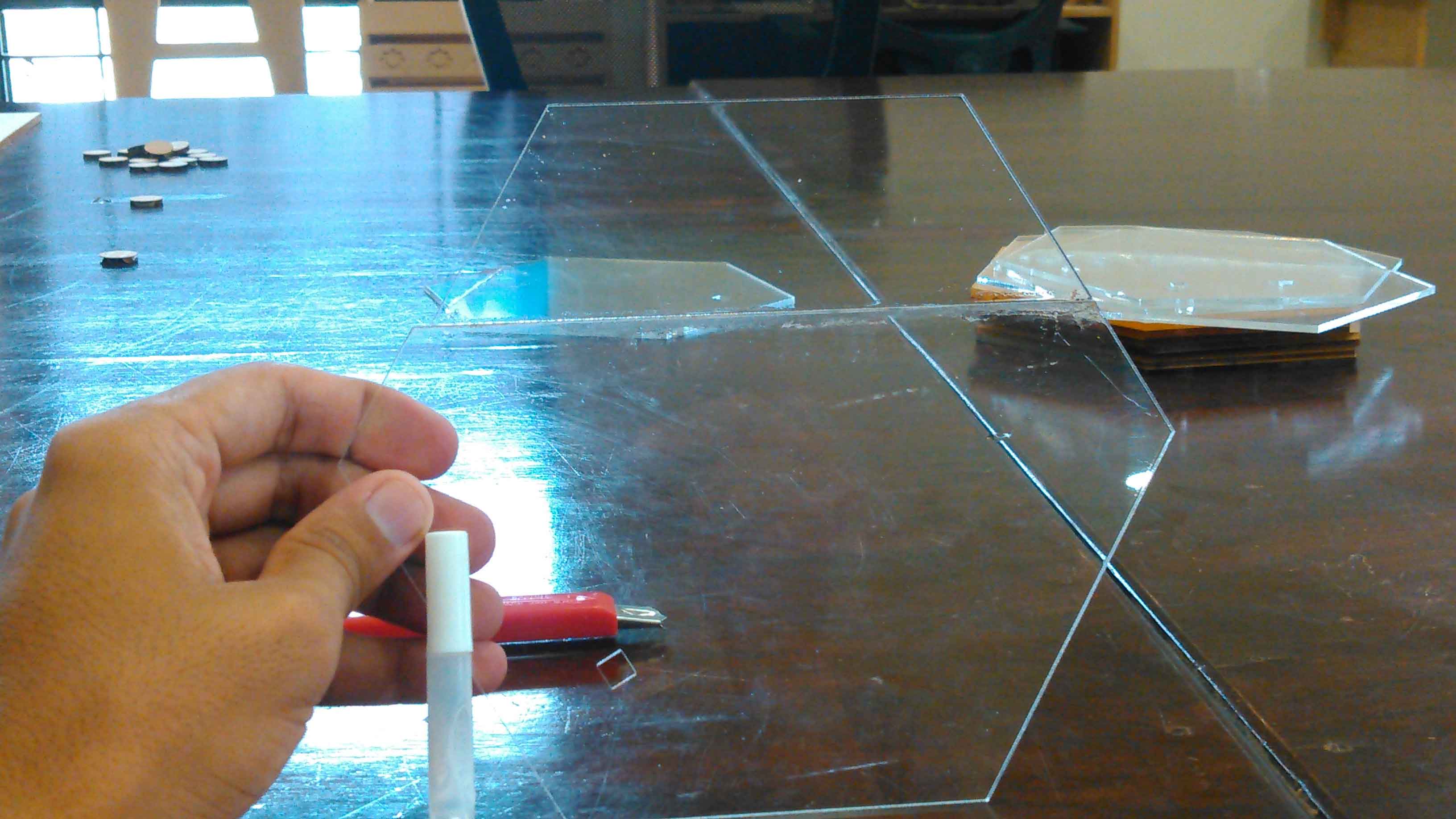
uisng Elfy glue to joined parts of door.
Along with doors I made handles on 6mm acrylic sheets, which is set to be cut within 0.5x0.5 ft sheet.
handle file for laser cutting process
Fixing Doors on Shelves
For fixing doors on shelves I am using hinges which I bought 24 in less than 1.04 dollar. I am using them, one side is glued on acrylic and the other part is fixed with 3mm screws on shelves.
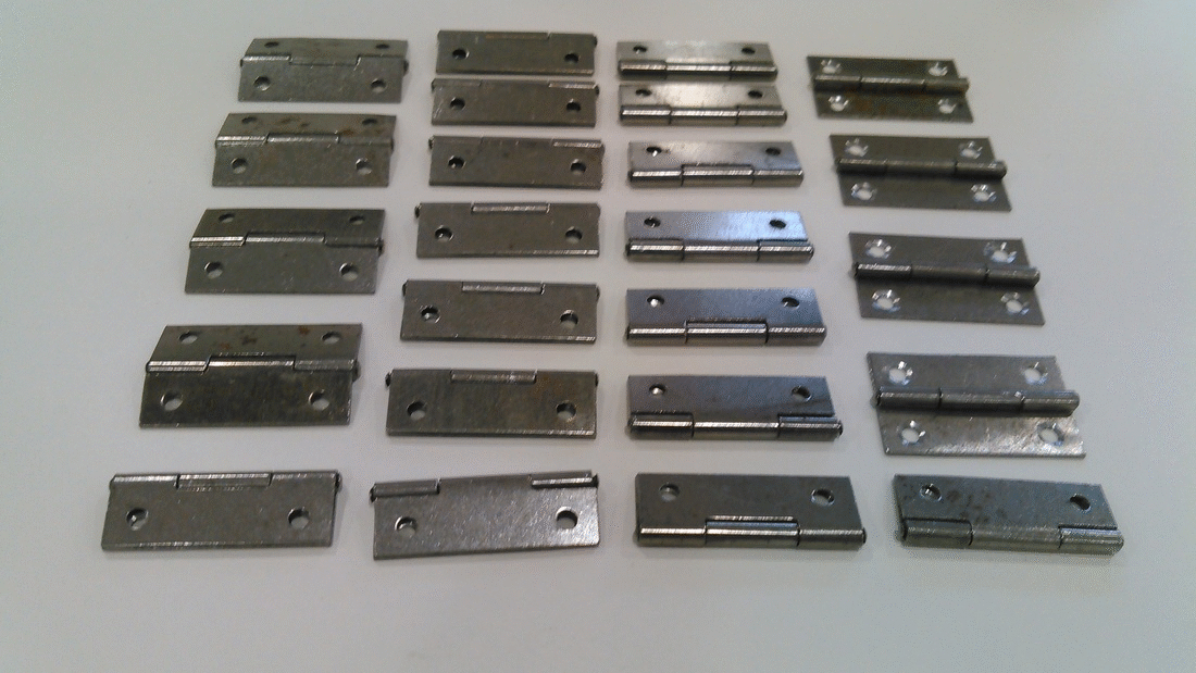
Cute and cheap Hinges
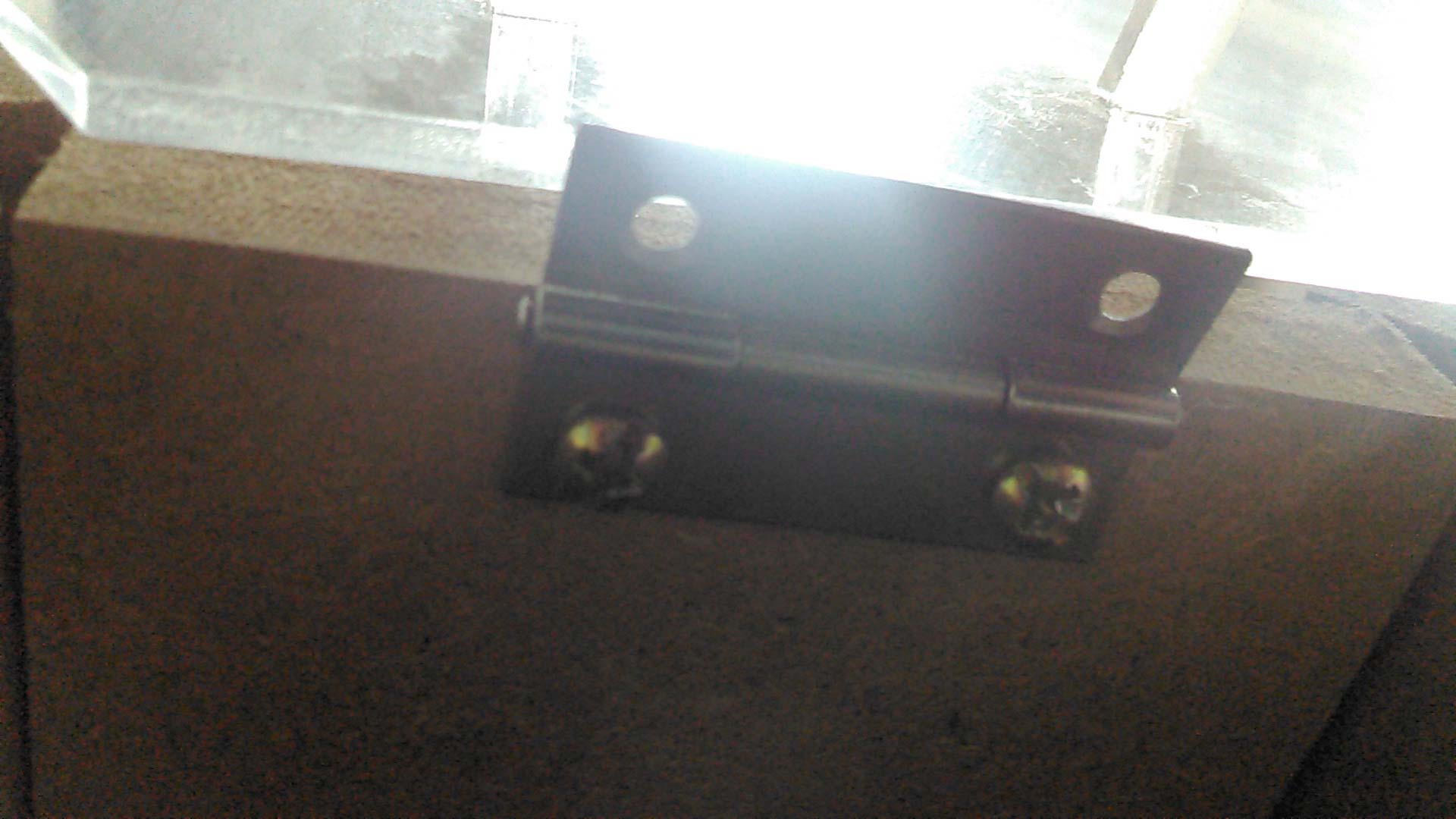
Hinge fix on shelf
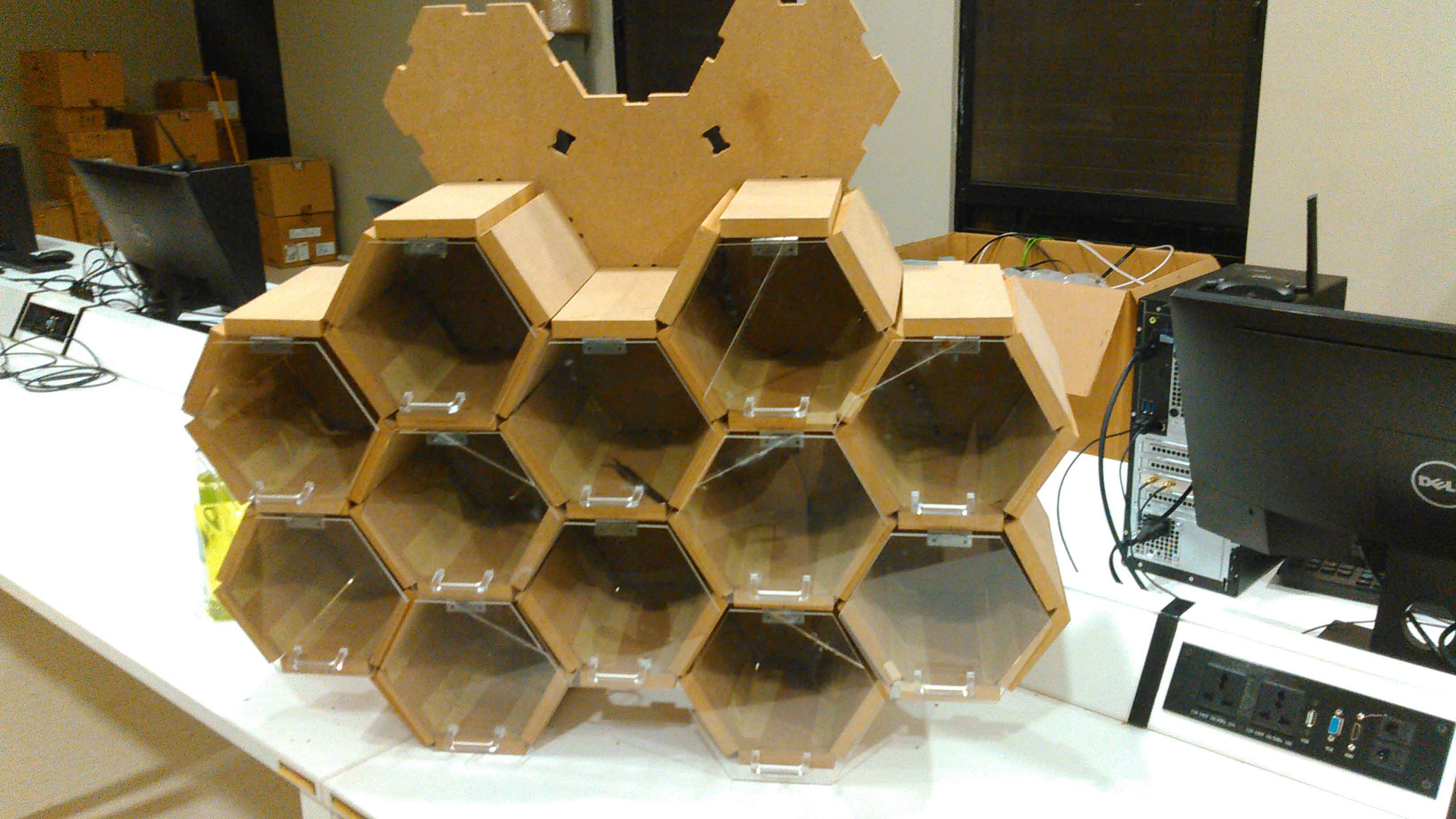
Fixed doors on whole structure
3D Box for Circuitry:
The circuits are discussed in next session of Electronic system. Here we only talk about 3D printed box for project circuitry. Like other design it is also first made in Solidworks. It consist of 2 parts one is box and other is cover (files are shared in this week files). The cover is not finished from one corner because of voltage fluctuation while 3D Printing but it is fitted perfectly thats why I used it.
Designing box
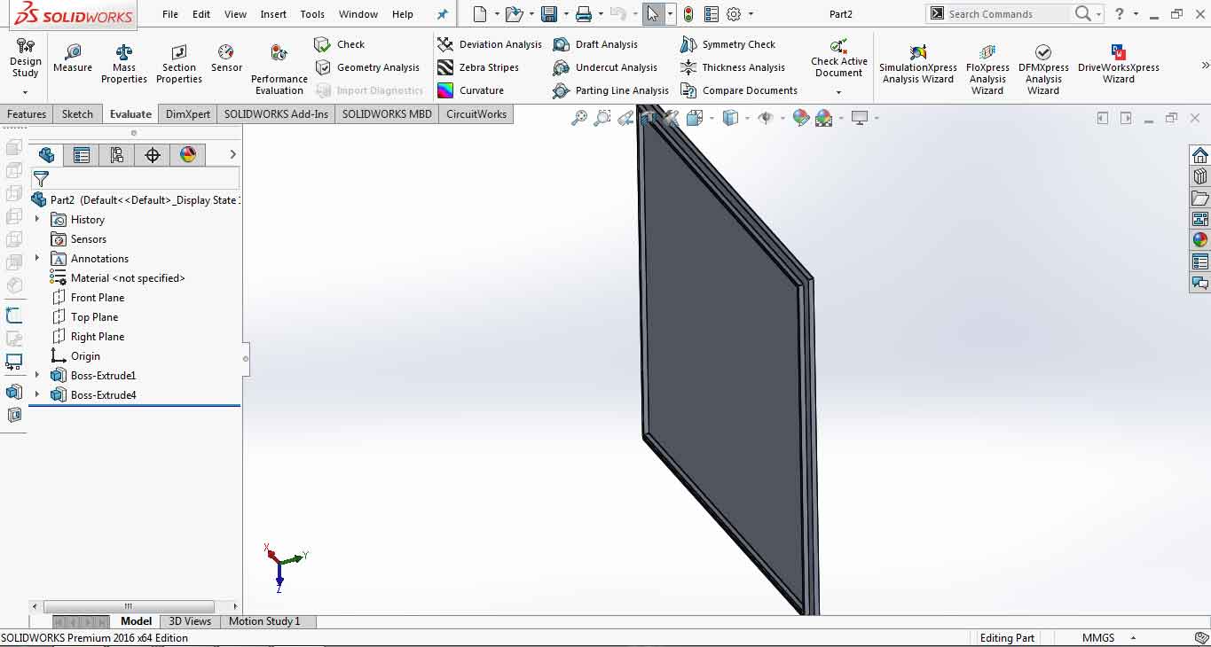
Designing box cover
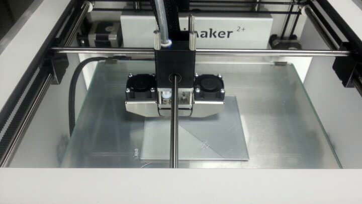
box while 3D Printing
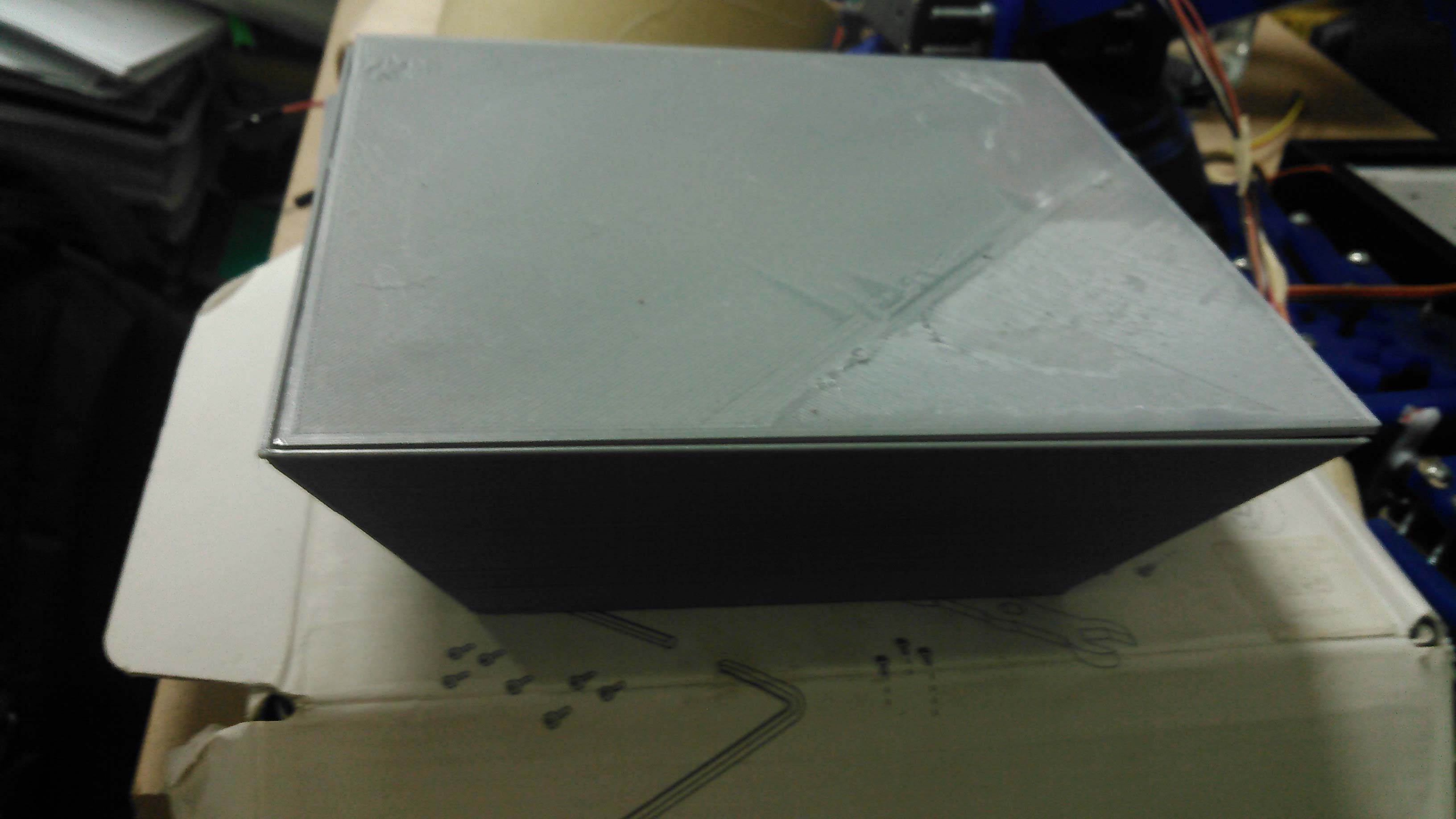
Finished 3D Printed Box and cover
Electronic System
In this part I am discussing other half of project which is electronic system includes circuit boards, wiring from circuit board to output RGB LEDs and programming of the system.
Circuit Boards
First of all the system is based on two circuits in which one is made in Week-12 Output devices and other is made in Week-14 Networking and Communications.
The main circuit we are using here is 328p board which is connected with RGB LEDs (placed in each shelf) and connected with supporting board (ESP-12E Programmable Board) which enables ability to connect with Wifi. Both of the circuit board is made by myself in FABAcademy course. We discuss each board one by one below.
ATMega328p Board
The board is based on ATmega328p microcontroller and developed in Output device week. Here are some features suppports by this board.
- Support Programming from FTDI Cable
- One general purpose button connected with Pin2 of Arduino
- Dedicated I2C Connector
- Dedicated Serial Connector
- General Purpose 4 Analog Pins A0, A1, A2 and A3
- General Purpose 8 Digital Pins in which 5 pins are PWM~. Pin3~, 4, 5~, 6~, 7, 8, 9~, 10
- LED is connected with Pin13 to work with LED_BUILTIN codes
- Dedicated 2x3 ISP Pins
- Controller RESET button
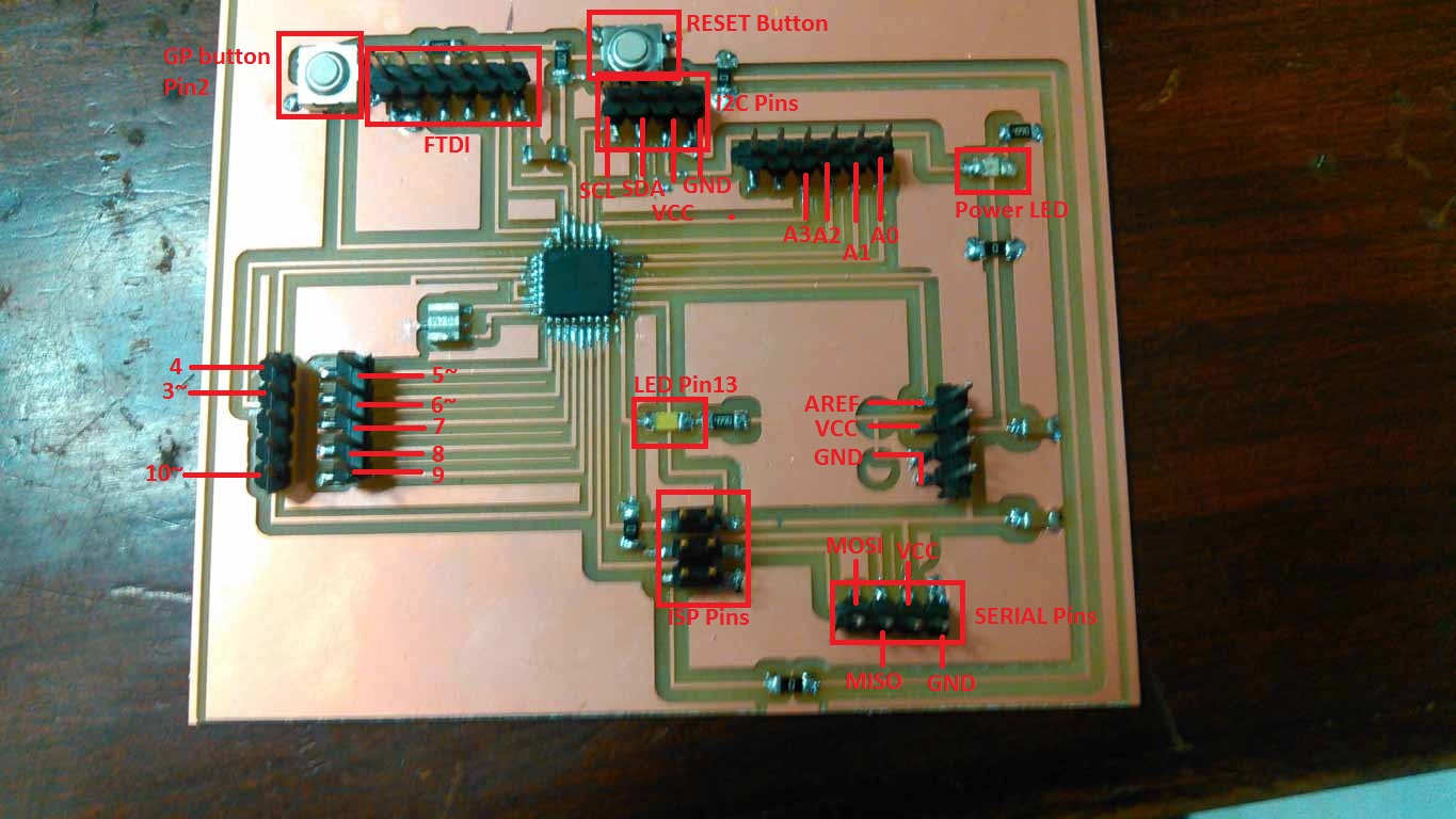
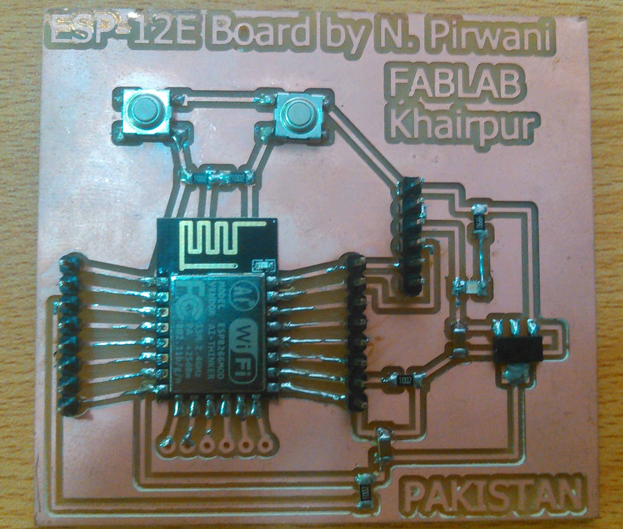
328p Board with Pin Description
To learn more about this board please visit this link of week-12. Here you can find everything from making to uploading code in this board.
ESP-12E Programmable Board
The board is based on ESP-12E controller processor and developed in Networking week. This board is designed by me, it doesn't require anything except FTDI Cable to program. It has manual way to upload code directly using FTDI Cable by pressing Flash and RESET buttons. ESP-12E in this project used to provide wifi ability to the system. It has a huge EEPROM memory which is enough to store inventory data (in my case). To learn more about this project please visit this link of week-14. Here you can find everything from making to uploading code in this board.
Programmable ESP-12E Board
Wiring
The system wiring is based on networking between 328p and ESP-12E board, connection from 328p board to RGB LEDs, and most importantily how RGB LED strip split to become output device in each shelf.
Networking between 328p and ESP-12E:
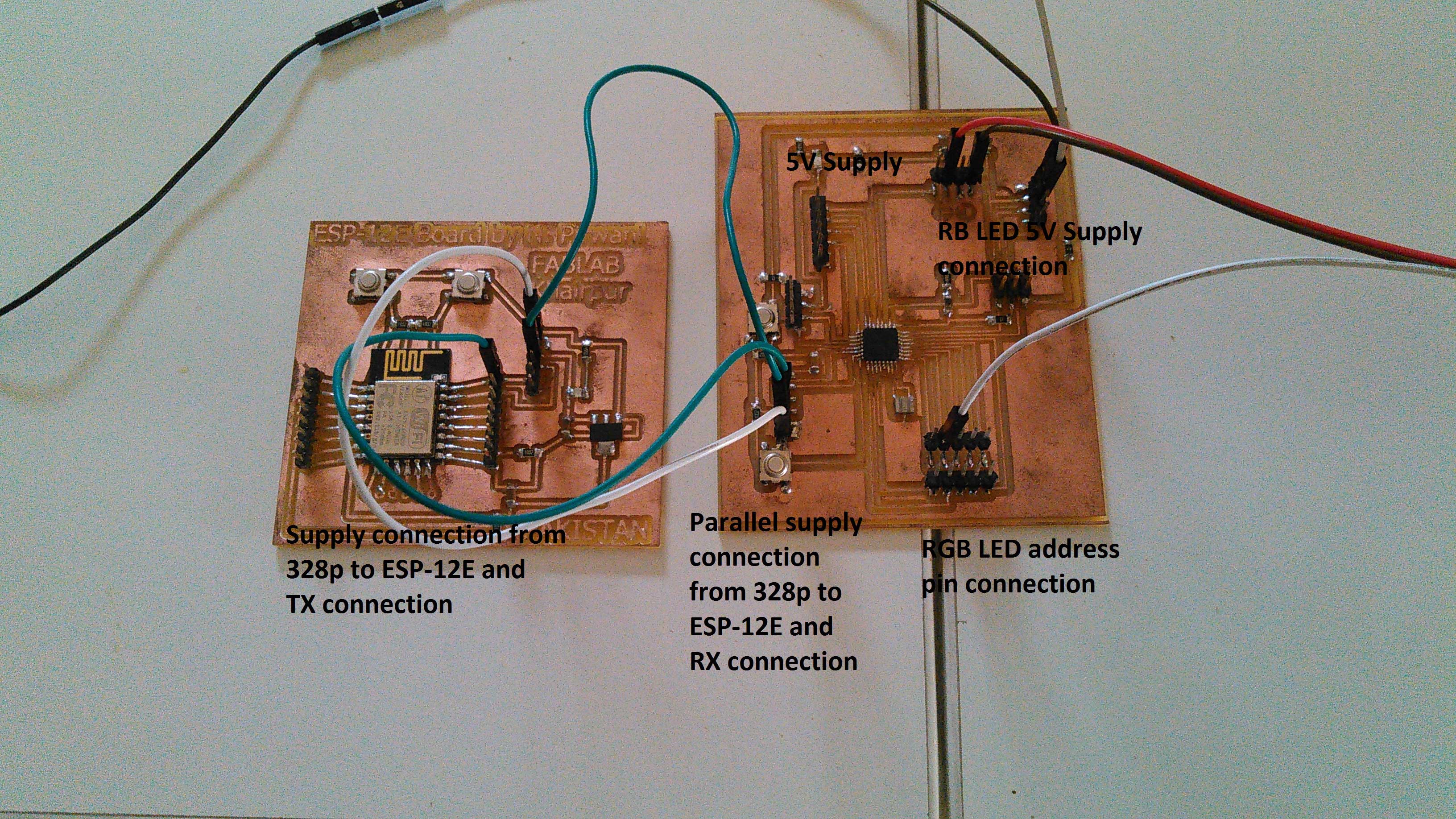
Connection between 328p and ESP-12E board
- 5V supply is given to 328p board which is connected parallel with ESP-12E so both board can power up.
- TX pin of ESP-12E is connected with 328p board RX pin because we only need to communicate in one way.
Making RGB LED output
First I cut RGB LED strip into pieces of 3 RGB LED for one shelf. As I have total 12 shelves so I used total 36 RGB LEDs for this project.
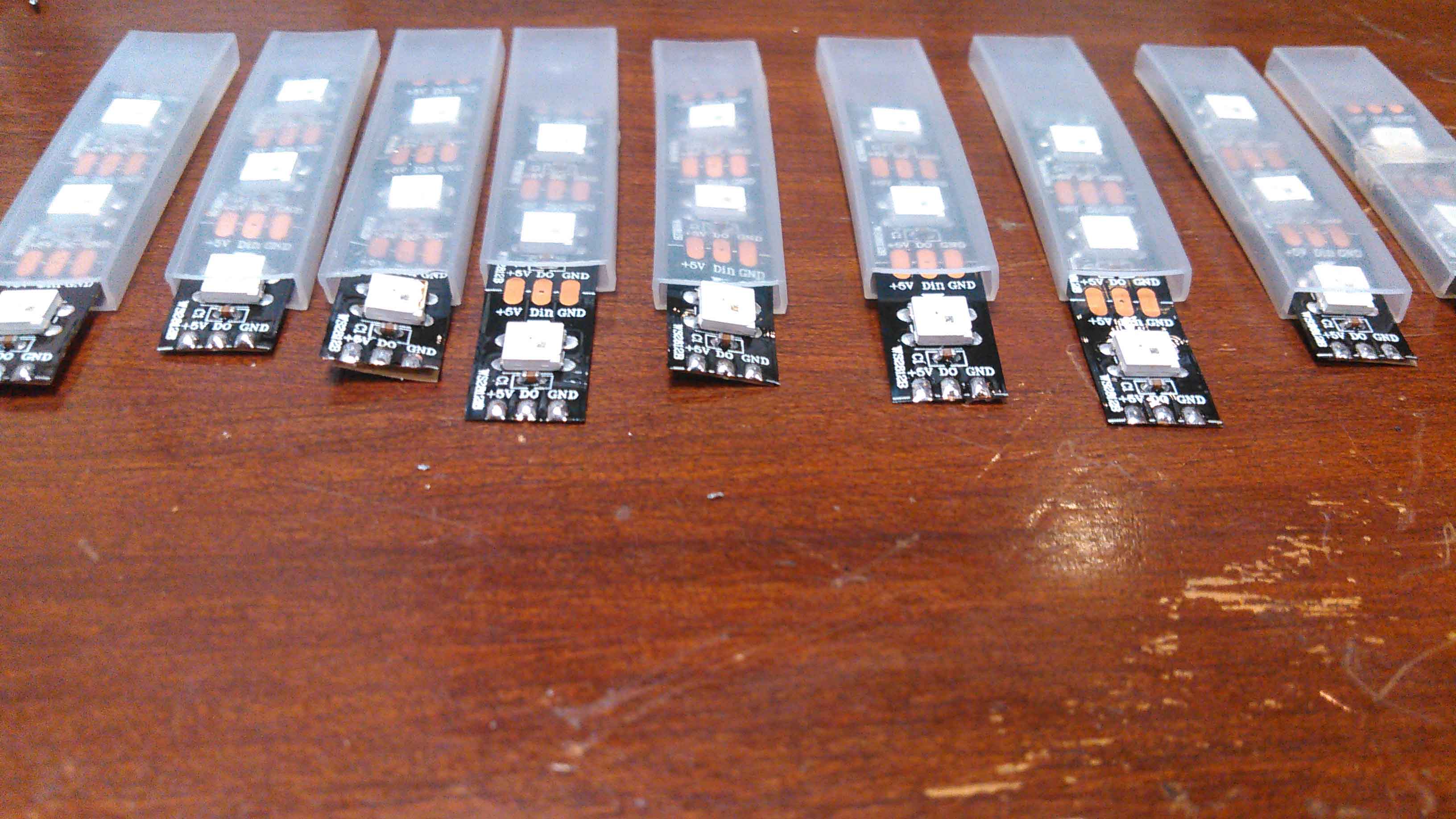
Cutted RGB LED strip into pieces of 3 RGB LED for one shelf
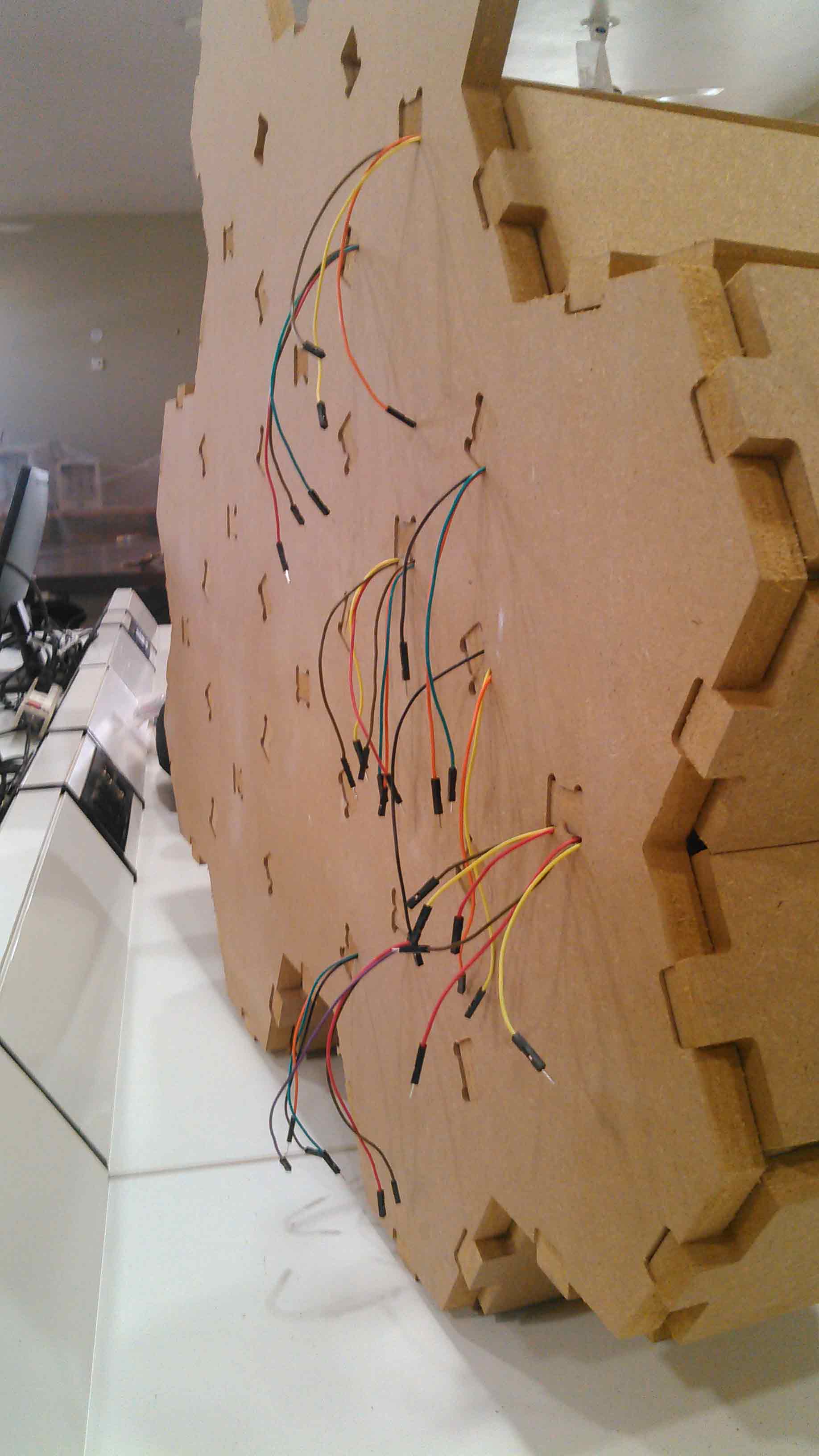
For connections I am using 36 male/male jumper wires and 36 female/female jumper wires cut all then from one side and sold with RGB LEDs. male connection on side of Dout and Female connectors with Din.
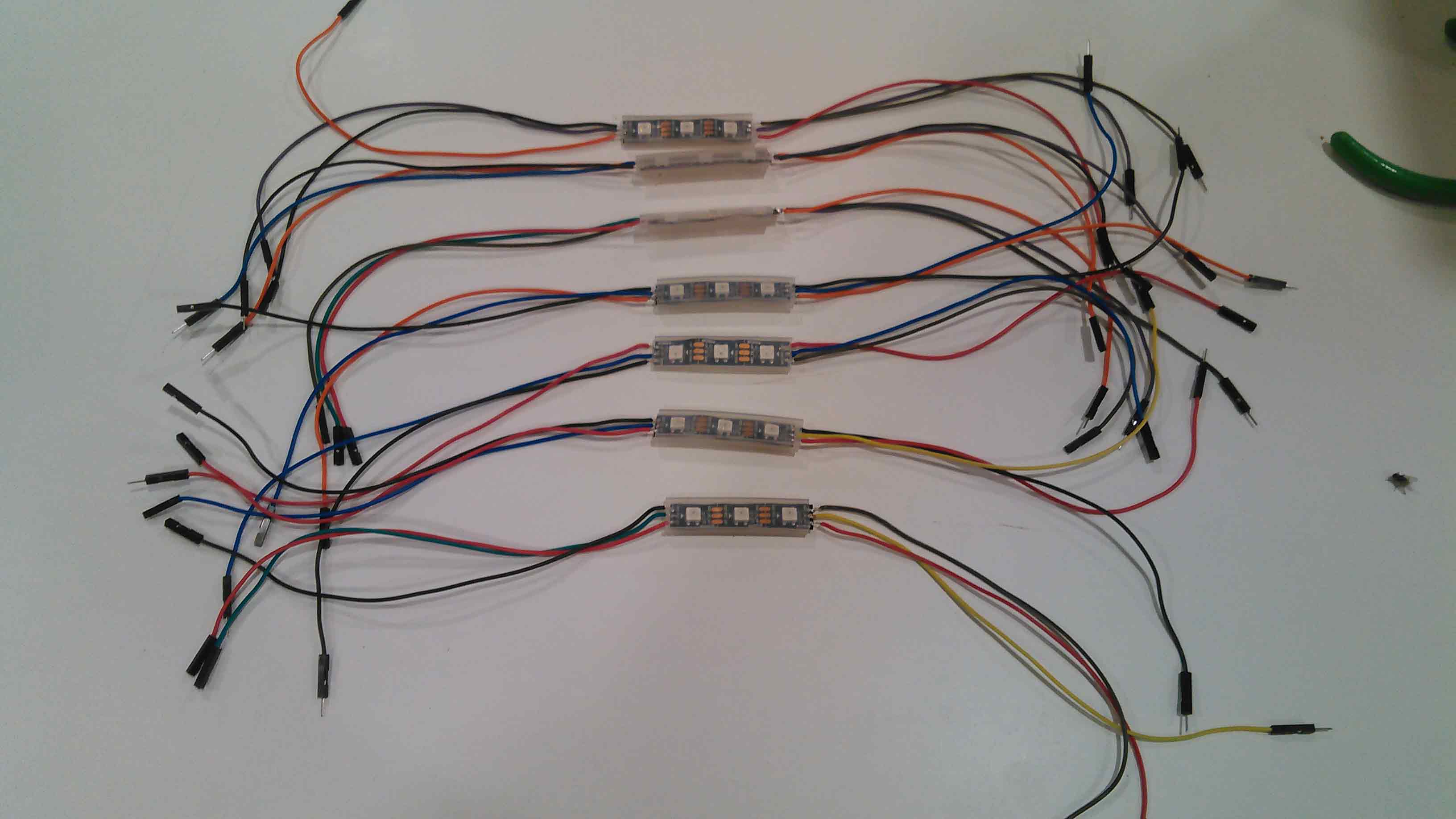
Soldered jumper wires with RGB LEDs
I accidently increased the size of dogbones while cutting holes on main structure. These dog bone holes used to pass the wires from shelves so I dont need to make specific holes for wiring in shelf.
RGB LEDs in shelf and wires are outside to conenct with other RGB LEDs
RGB wires showed outside while wiring
As I mentioned I put one side of RGB as male wire and other side to be as female wire the reason for this is that these are addressable RGB LEDs. The connection between RGB LEDs are Din of 1st RGB is connected with controller, Dout of 1st RGB is connected with Din of 2nd RGB and the chain and so on. After fixing RGB LED strip with in shelves I connected there wires. 2 Wires are for 5V supply which is connected with main supply and address pins are connected to pass the signal.
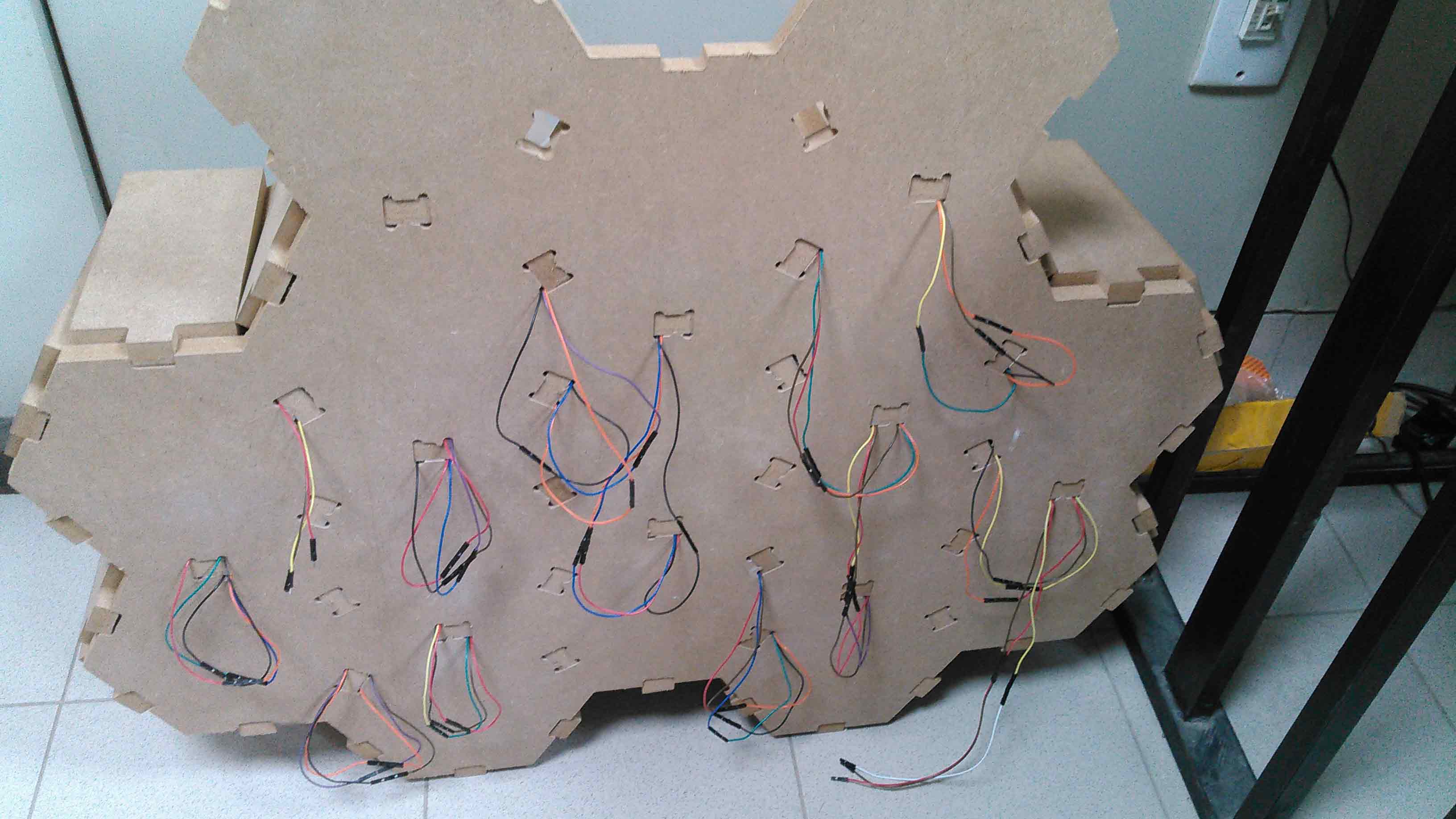
Connection between RGB LEDs
In the next part whole system is powered with 5V supply, my chinese mobile adapter with capacity of 5V and 2 Amp is used as power supply for this project, whole electronic system is connected together and settled in 3D Printed Box to connect with system.
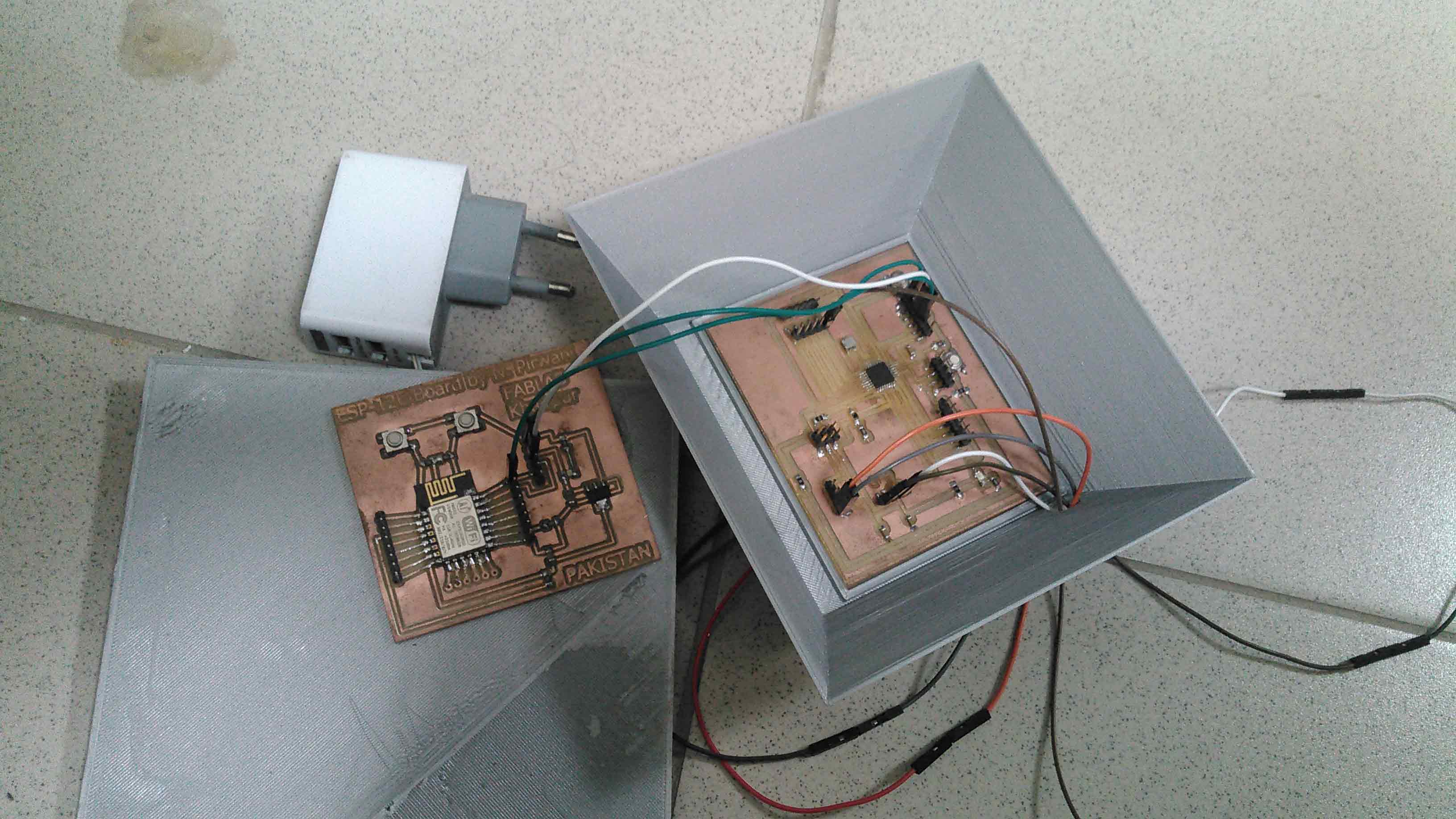
Eletronic System fitted in 3D printed box along with power supply
Programming
Before jumping to this part it is important to visit week-12 and week-14 first, there you can find libraries and other basic stuff which is important to understand programming in above mentioned board.
Both boards are programmed using Arduino IDE, I split code in different parts and explain each part while sharing code below.
Code for ESP-12E Board:
Code for 328p Board:
User Interface
User interface will be displayed on either mobile phone or laptop of user it consist of list of items which is on buttons and when a person pressed that button a pop-up will show to ask the quantity of item which a person needed or added in inventory and a button to locate the item. When a person press the locate item RGB LEDs will blink of that specific shelf.
User interface demosntration on laptop
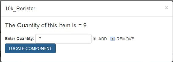
pop-up window
End Result
After interfacing and asking to locate desired component in inventory system. The RGB LEDs blink in a box to locate the component.
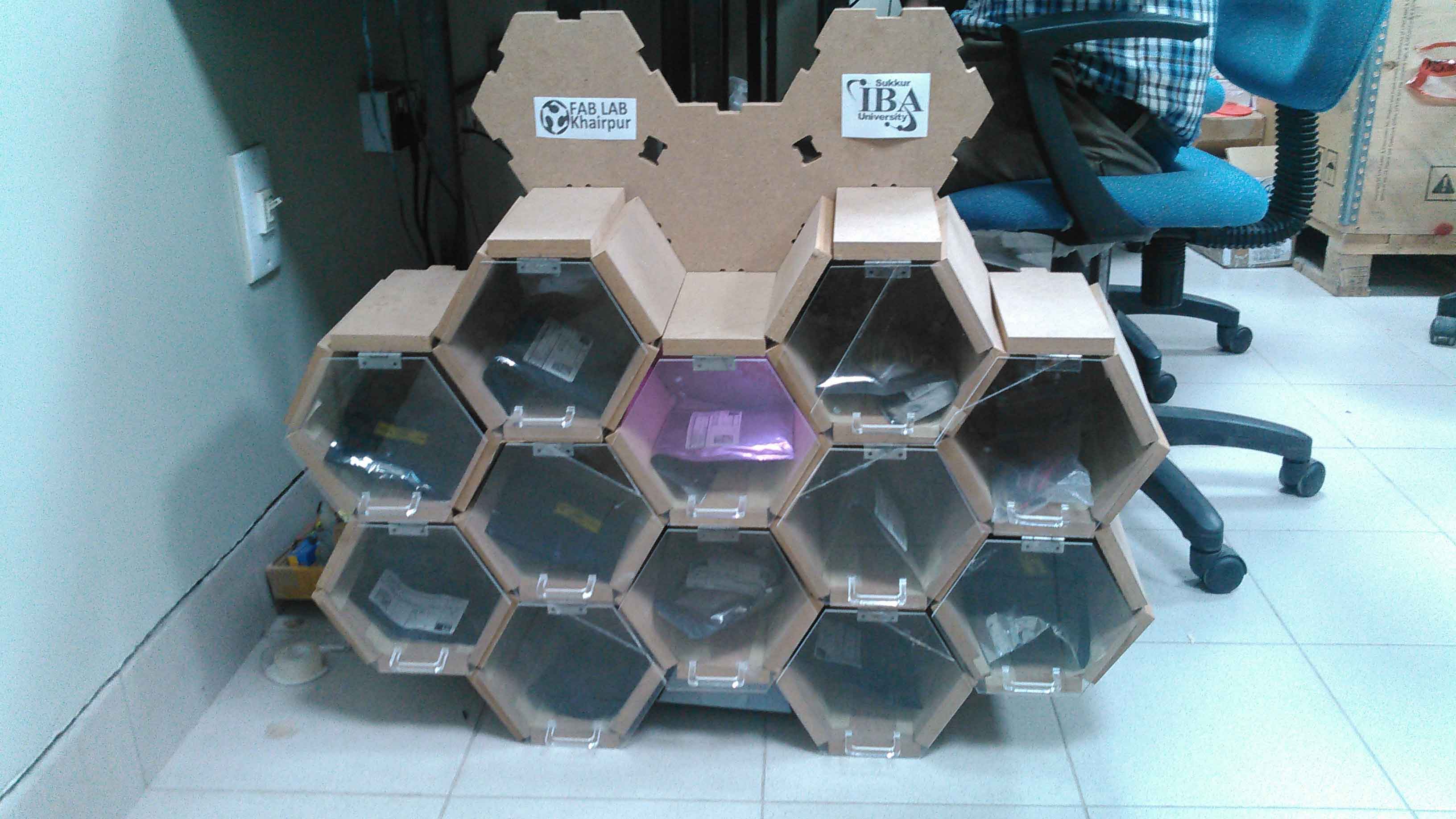
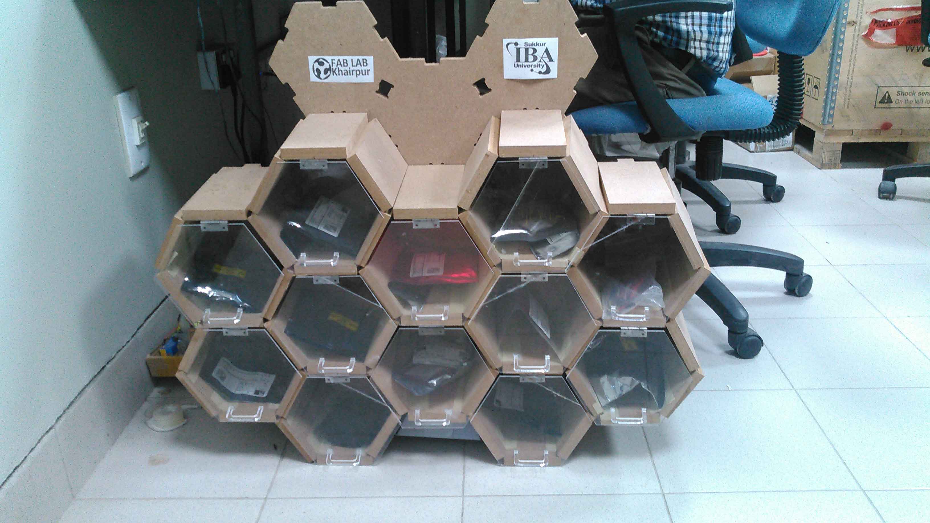
System locating desired component with different effects of RGB.
Picture which is set above this description is shown at web server
Bill of Material (BOM):
| Components | Number of components * Price of components(USD) | Total price (USD) | link |
|---|---|---|---|
Further Improvements:
There is always a space for innovation in everywork. There are many things which is possible to do in this project for improvements. I mentioned some of improvement which I think i'll worked later to make this project more better and to make it as product from prototype
- Stop button in user interface to stop locating component (after locating).
- Making interface more intelligent to give user an admin rights to increase no. of components in the list if he wants to connect the system with other shelves of LAB.
- Making it with some other kind and thinkness of wood to make it more light weight.
- A limit switch is installed with doors or some other kind of sensor present to inidcate how much time a box is opened to change the inventory.
- A camera is fixed with system to check "who take what".
- Making application in which only specific user can use this system. Password and ID is provided to track who take what from inventory.
Acknowledgment:
Allah - beginning with the name of - the Most Gracious, the Most Merciful . All praise is due to Allah; we praise Him, seek His help, and ask for his forgiveness. I am thankful to Allah, who supplied me with the courage, the guidance, and the love to complete this course. Also, I can not forget the ideal man of the world and the most respectable personality for whom Allah created the whole universe, Prophet Mohammad(Peace Be Upon Him).
I would like to acknowledge my deep gratitude to Professor Neil Gershenfeld, director of Fab Academy whose lectures increases our exposure and encourage us to learn more, specially thanks to Vice Chancellor Sir Professor Nisar Ahmed Siddqui along with his team whose vision and mission make FABLAB possible in Pakistan. My instructors Sir Sohail Ahmed Soomro, Sir Fida Hussain Memon, Sir Nisar Ahmed Siddiqui and Sir Asim Ali Samejo who guide me with best of their knowledge in everyweek to complete the task. There are other honourable mentions like Nuria Robles for weekly reviewing my assignments, Francisco Sanchez Arroyo who is always available on Whatsapp for resolving my tecnhnical problems, My brother, Zaid Pirwani (my personal google) who is available on a single phone call to resolve my issues and Nasir Jumani who help me to plan and rethink where I badly stuck. My colleagues who always their to hand me complete group assignments. and all those who are available and somehow help me to complete this course I thank you all. Finally I thank to my family and friends who encourage me, financially support me and emotionally attached with me when I need them.
What I learned, made and shared here is thanks to you all.
"Click here"to download all files of this week

This work is licensed under a Creative Commons Attribution-NonCommercial 4.0 International License