
|
| Sukkur IBA University Merit, Quality, Excellence |
WEEK-14
Networking and Communications
Lecture & Recitaton of a Week:
Lecture on 25th of April, 2018: Networking and Communications by Neil Gershenfeld
Recitation on 30th of April, 2018: fabricademy by Anastasia Pistofidou, Cecilia Raspanti and Fiore Basile
Tasks for a Week
- individual assignment: design and build a wired &/or wireless network connecting at least two processors
- group assignment: send a message between two projects
Individual Assignment
Task of this week is to design and build a network connection between atleast two processors, as I worked in building application to interface between 328p board and esp-12e board. In this week I mentioned the making of programmable ESP-12E board and the connection between both boards. to worked with application I made in last week assignment.
Making of Programmable ESP-12E board
I want to use ESP-12E as a controller so I want to make a circuit to directly connect it with PC to program. On searching internet I found this circuit on instructables which uses Arduino Uno to program ESP-12E, After reading a whole article there are two problems which I understand one is UNO is used in this circuit just t0o provide RX TX to ESP-12E, If I maybe made the same circuit and replace UNO with FTDI cable then maybe it works. 2nd problem that the article describe ESP-12E to program with AT commands which I don't want to do.
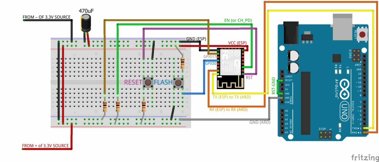
Circuit connected with UNO to work on AT Commands. here is the link
I used above circuit to replace UNO with FTDI cable and made my own circuit which includes Flash and RESET buttons. The making of circuit is mentioned below.
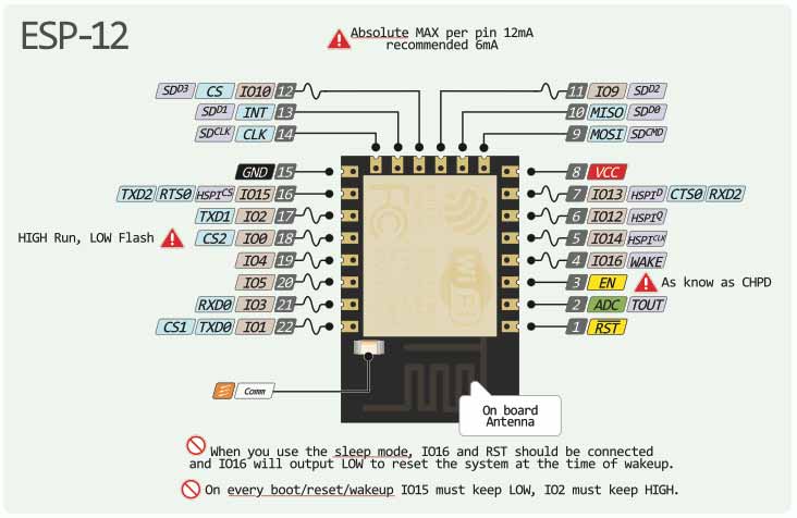
ESP-12E Pin Description
PCB Designing
For PCB designing I worked on Eagle 7.5 (an introduction of this software is mentioned in Electronic Design Week). First I made a schematic of board:
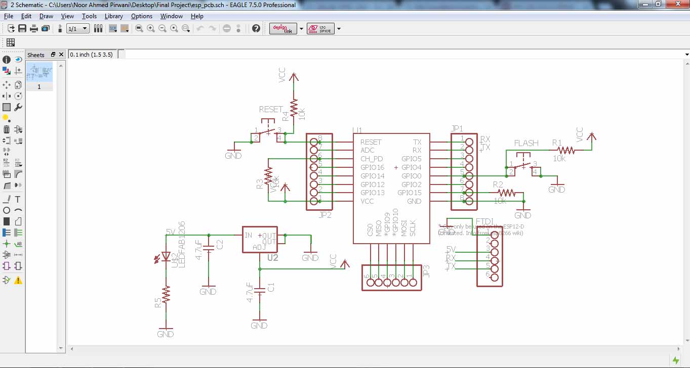
ESP-12E Board Schematic
then I generate PCB board and route it.
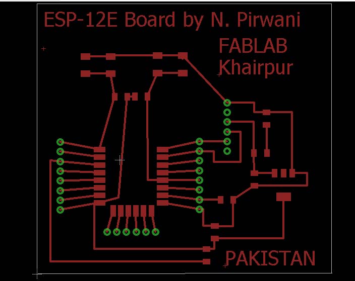
PCB Design
Generating .RML Files
For generating RML files, first I need my PCB design in .png format for that I export my PCB design in .png while setting up 2000 dpi and Monochrome
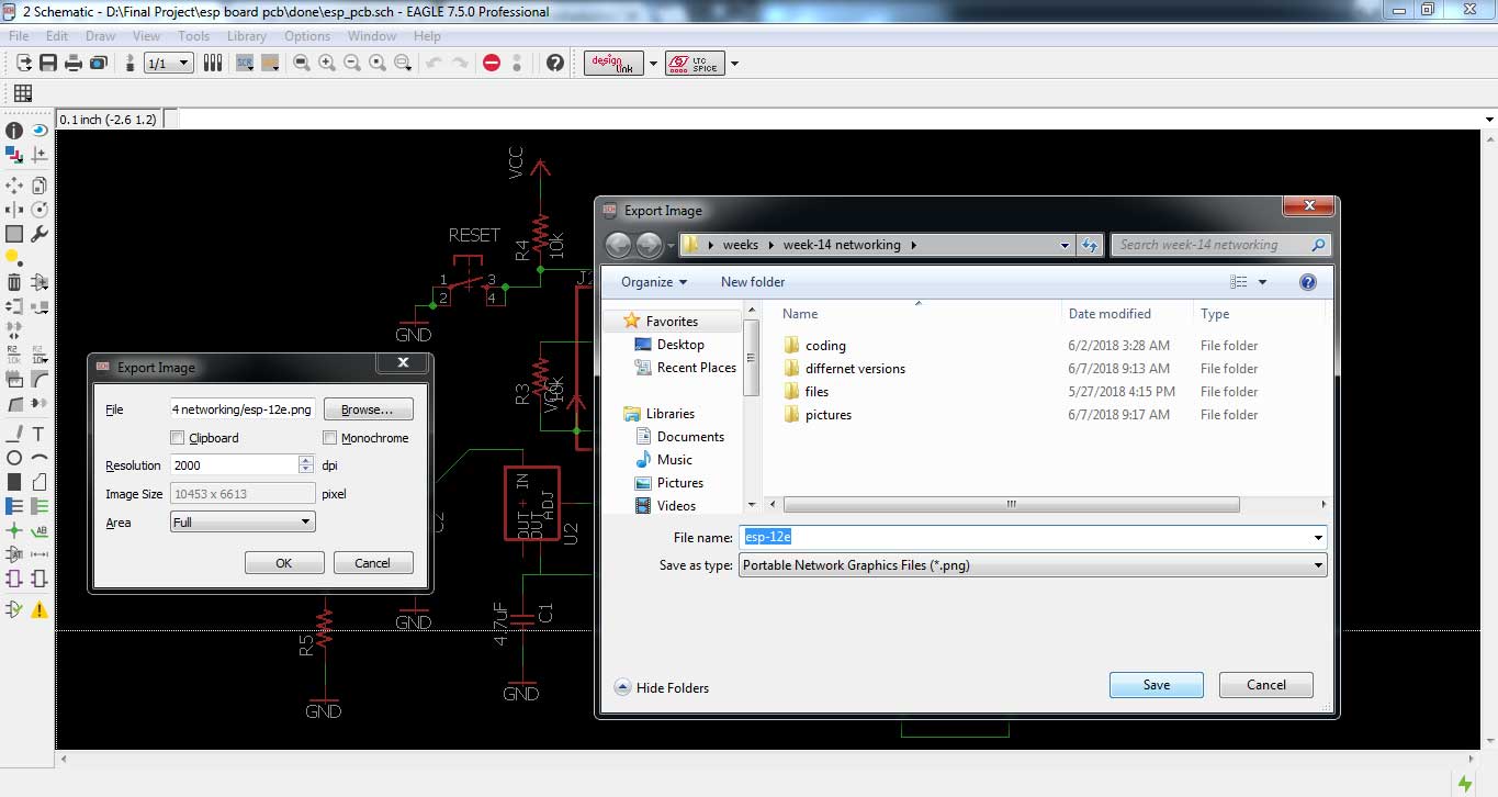
Exporting PCB design into .png format
.png is processed in Paint for making seperate files for traces, outline and drill holes of a PCB design
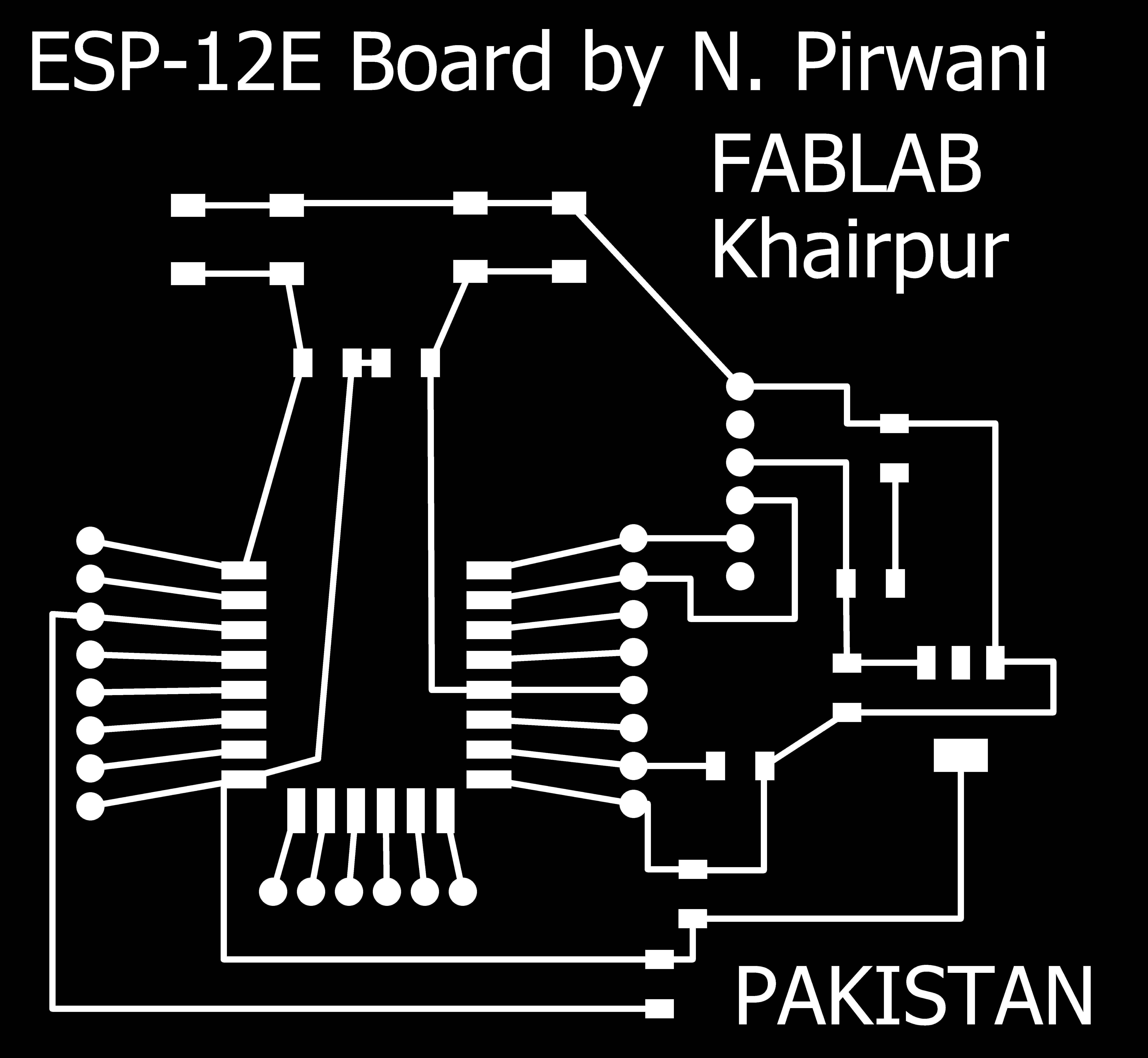
PCB traces

PCB Outline

PCB Drill holes
after making traces, outline and drill holes of pcb I used fabmodules to generate RML files of both traces and outline, all important settings are mentioned in a pictures below, for detailed fabmodules settings visit Electronics Production Week
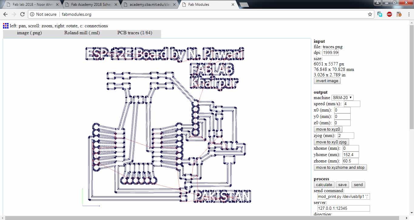
generating .rml file of PCB traces
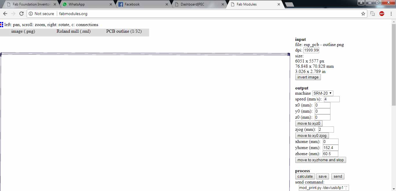
generating .rml file of PCB outline
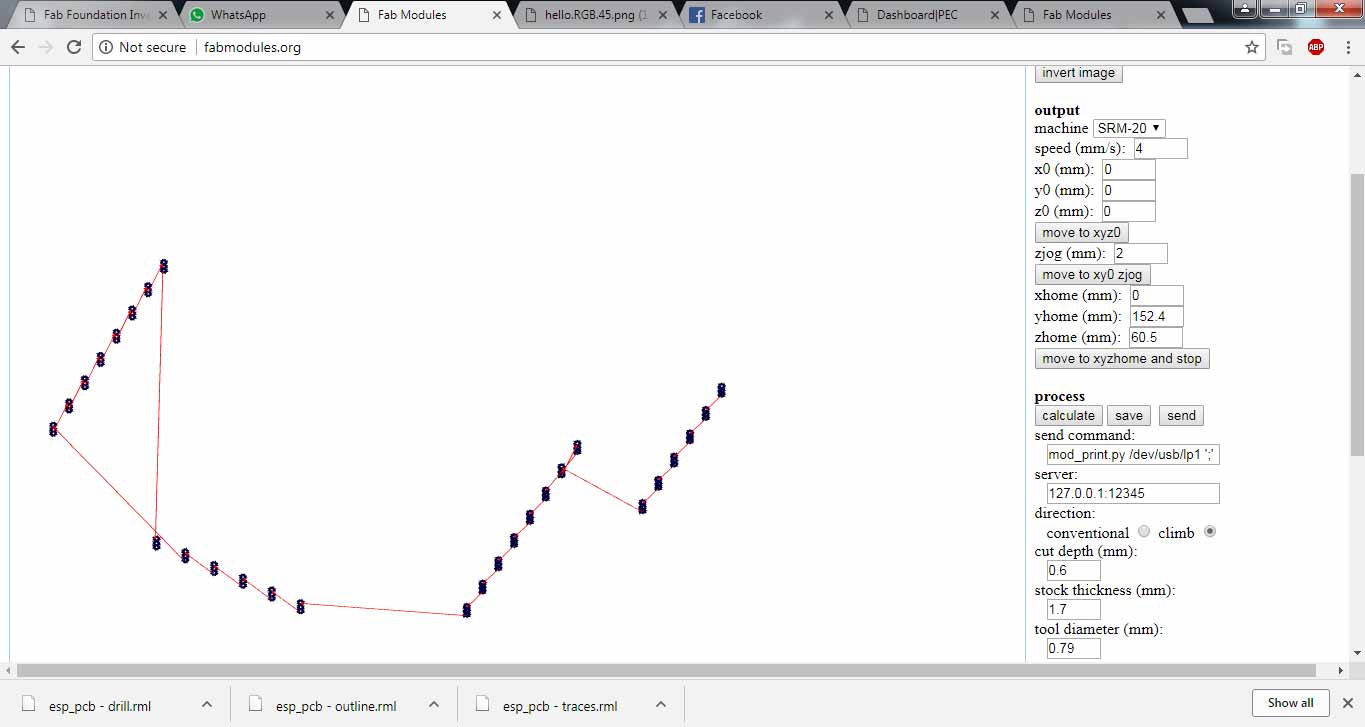
generating .rml file of PCB drill holes
Milling and Soldering
.rml files are given to Roland SRM-20 for milling, 1/32 drill bit is used for cutting outlines and for drill holes, and 1/64 bit drill is used to make a trace on a board and here is the result.
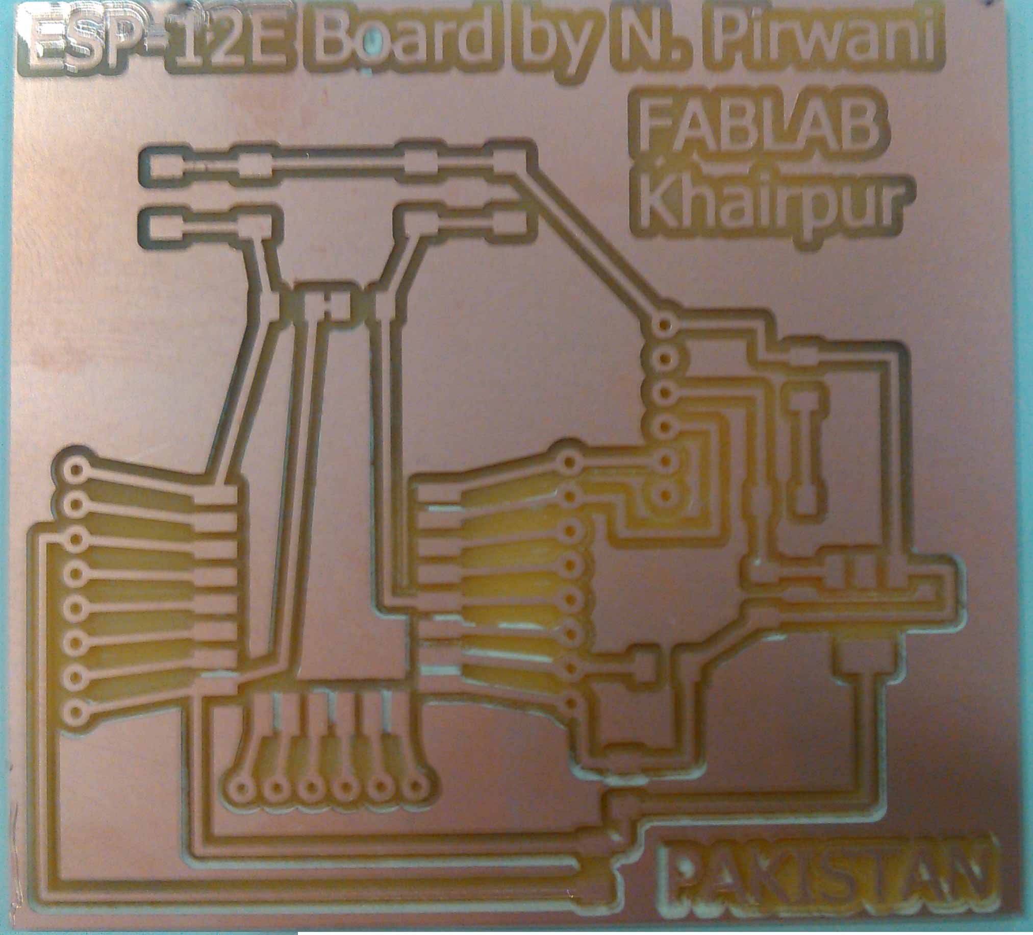
Milled board
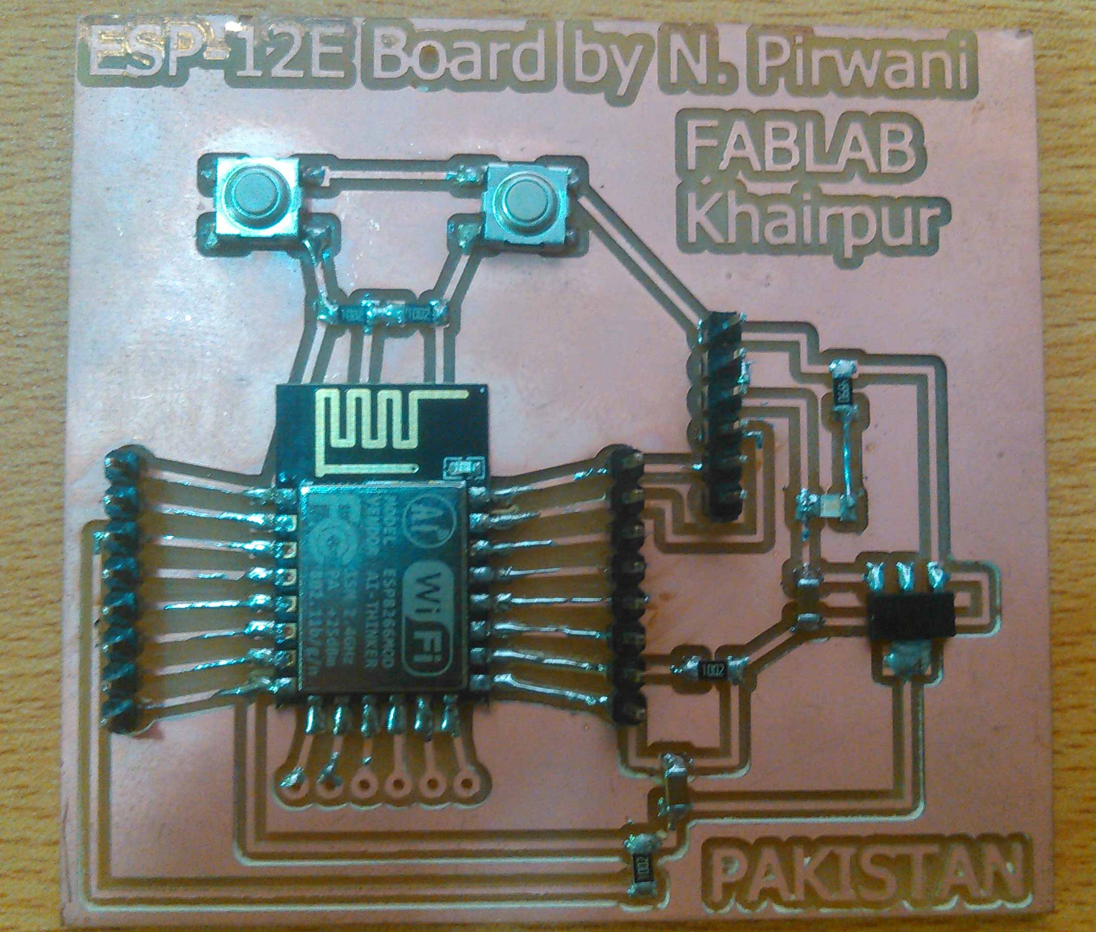
Soldered and ready to burn board
Programming the board
To program the board I found one tutorial at randomnerdtutorials.com. The tutorial is about making a webserver on internet using ESP8266.

Picture from randomnerdtutorials.com
As per instructions from above link, to program ESP-12E first I need to download the information of board from internet by copying this address in File>Preferences>Additional Boards manager URLs: http://arduino.esp8266.com/stable/package_esp8266com_index.json , in Arduino IDE.
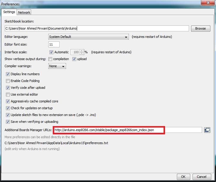
Preferences in Arduino IDE
Now goto Tools > Boards > Board Manager... and install esp8266 by ESP8266 Community
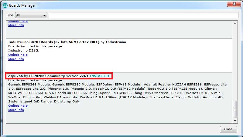
Required package installation
Now again goto Tools and select these settings before connecting ESP-12E board with computer
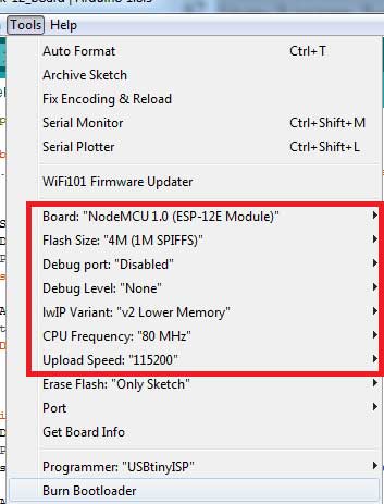
Settings for ESP-12E for programming ESP-12E
After setting up the board I copied the code from the tutorial and upload it into PC, uploading is fun because it is the manual procedure while uploading the code we need to press the FLAsh button and when it shows "Uploading" on arduino IDE build screen then it needs one time restart button to press.
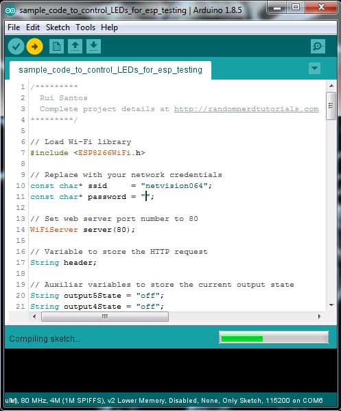
Compiling and Uploading code in ESP-12E programmable board
Code Successfully work in ESP-12E board
Uploading codes and Making connections
After making ESP-12E board now back to Networking assignment, the application to interface this week network is already made in week-13 assignment, I change a little bit in coding of week-13 and upload it in both of the board ESP-12E board and 328p board, the program is to control RGB patterns by pressing different buttons on screen
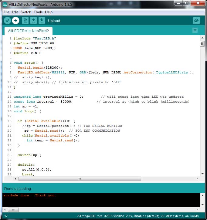
Uploading code in 328p board
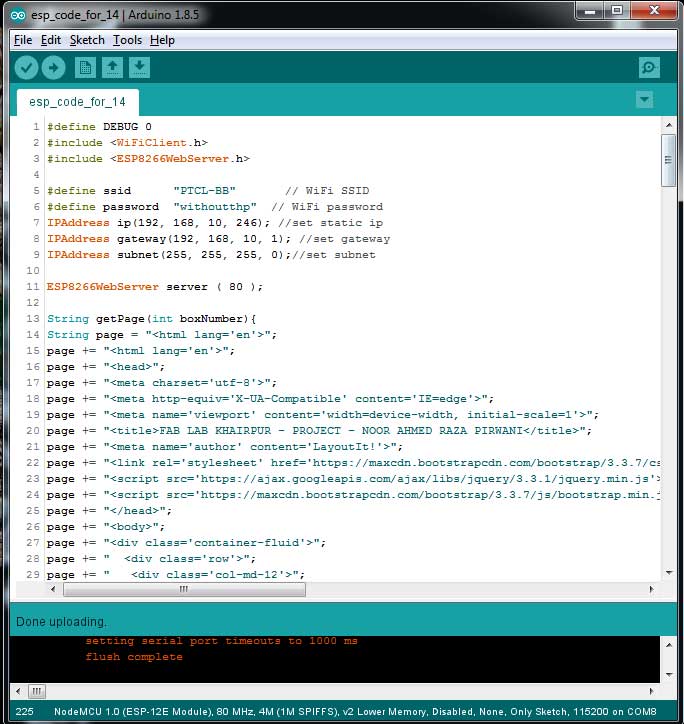
Uploading code in ESP-12E board
Now its time to make connection between both the boards.
- Connect both circuits VCC and Ground and connect them with 5V power supply
- ESP-12E board TX pin is connected with RX pin of 328p board
- RGB strip VCC and GND is connected with VCC and GND of 328p board (not compulsory but connected with same source), and data pin is connected with PIN 6 of 328p board
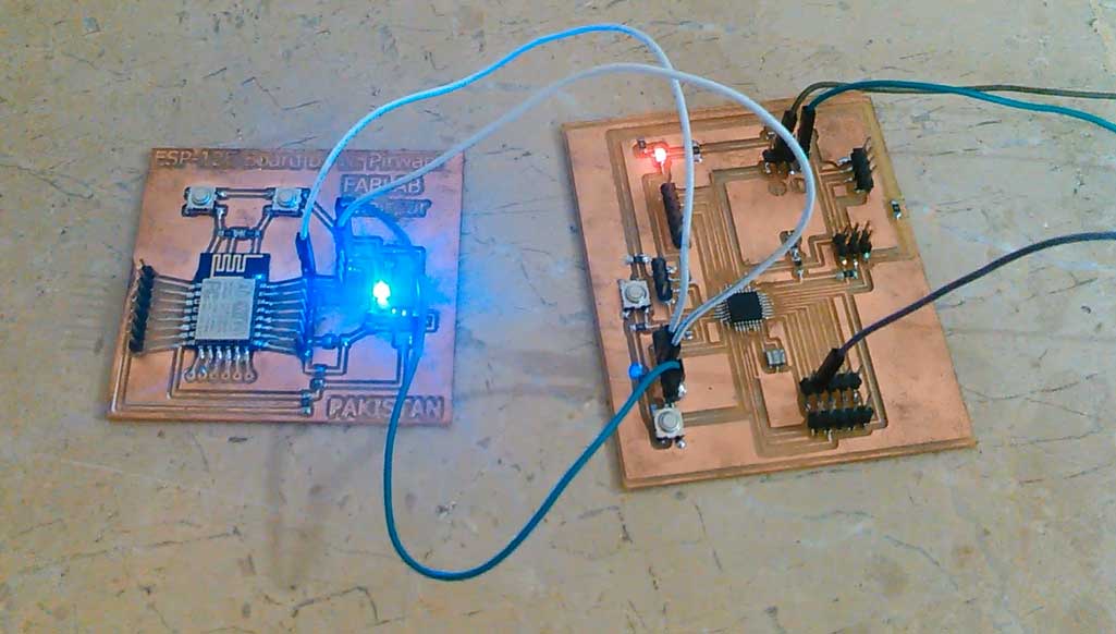
Connections between boards
Result
For checking application interfacing of this assignment please visit: Application and interfacing week. Here are the result in which ESP-12E is transmitting signal to 328p board which is displaying differnt patterns on RGB LED strip.
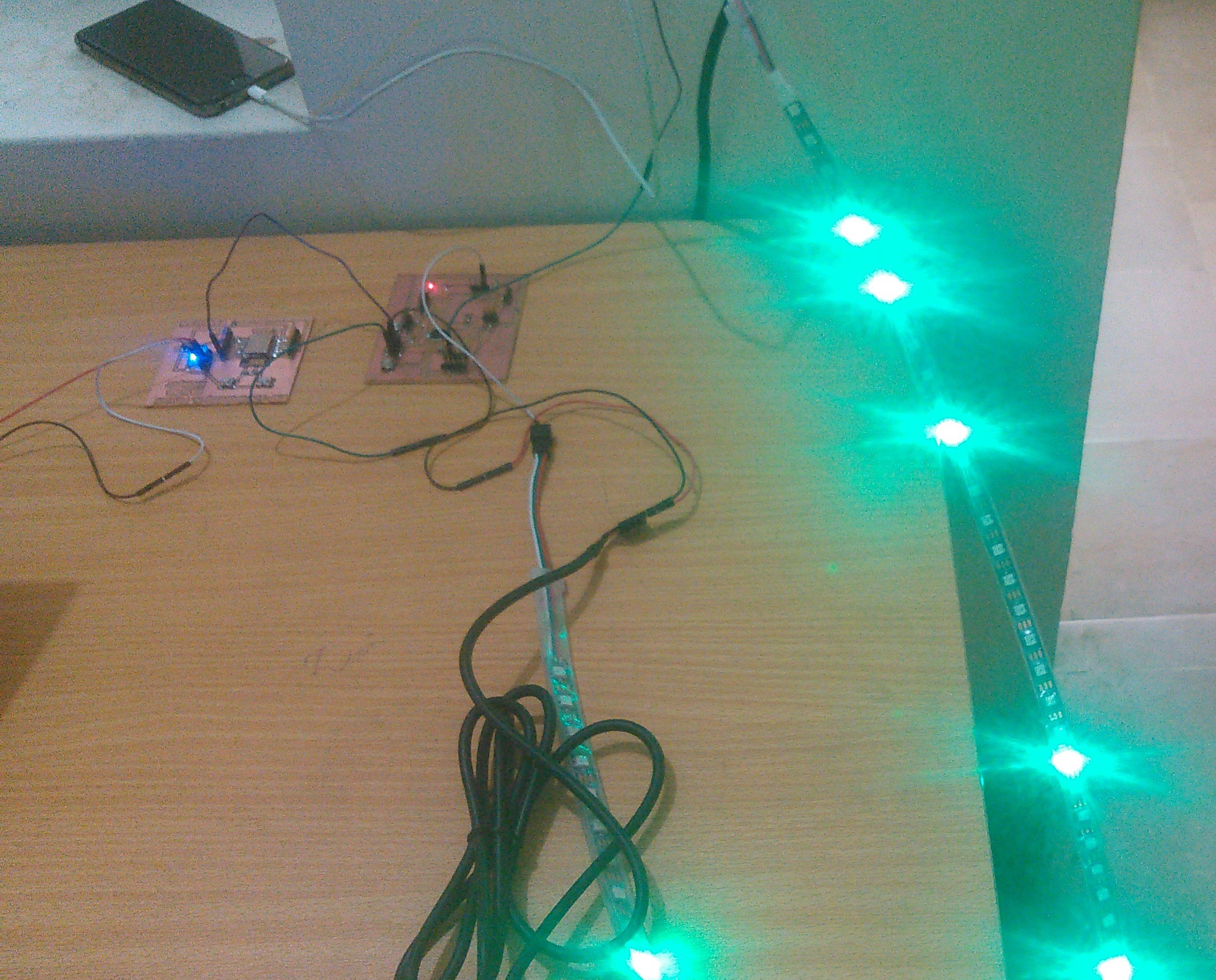
Different patters display using ESP-12E and 328p board
"Click here"to download all files of this week

This work is licensed under a Creative Commons Attribution-NonCommercial 4.0 International License