
|
| Sukkur IBA University Merit, Quality, Excellence |
WEEK-8
Computer-Controlled Machining
Lecture & Recitaton of a Week:
Lecture on 7th of March, 2018: Computer-Controlled Machining by Neil Gershenfeld
Recitation on 12th of March, 2018: human fab lab by David Ott
Tasks for a Week
- group assignment: test runout, alignment, speeds, feeds, and toolpaths for your machine
- individual assignment: make something big
Group Assignment
We are unable to do this week task on time because our ShopBot was not in operational condition, so we complete the work till designing and leave this week task until Mr. Francisco Sanchez who is in contact with our instructors come to fix the machine, and then suddenly in Week-12 he got the visa to visit Pakistan and came here to rescue our week-8 tasks. Not only how to run ShopBot, we learn many things from him.
Group Selfie with Mr. Francisco
In group assignment we done 2 things, as our machine is working first time, we need a flat surface platform for it. Second we make a test part which help us to set the size of slots in our Individual Assignments.
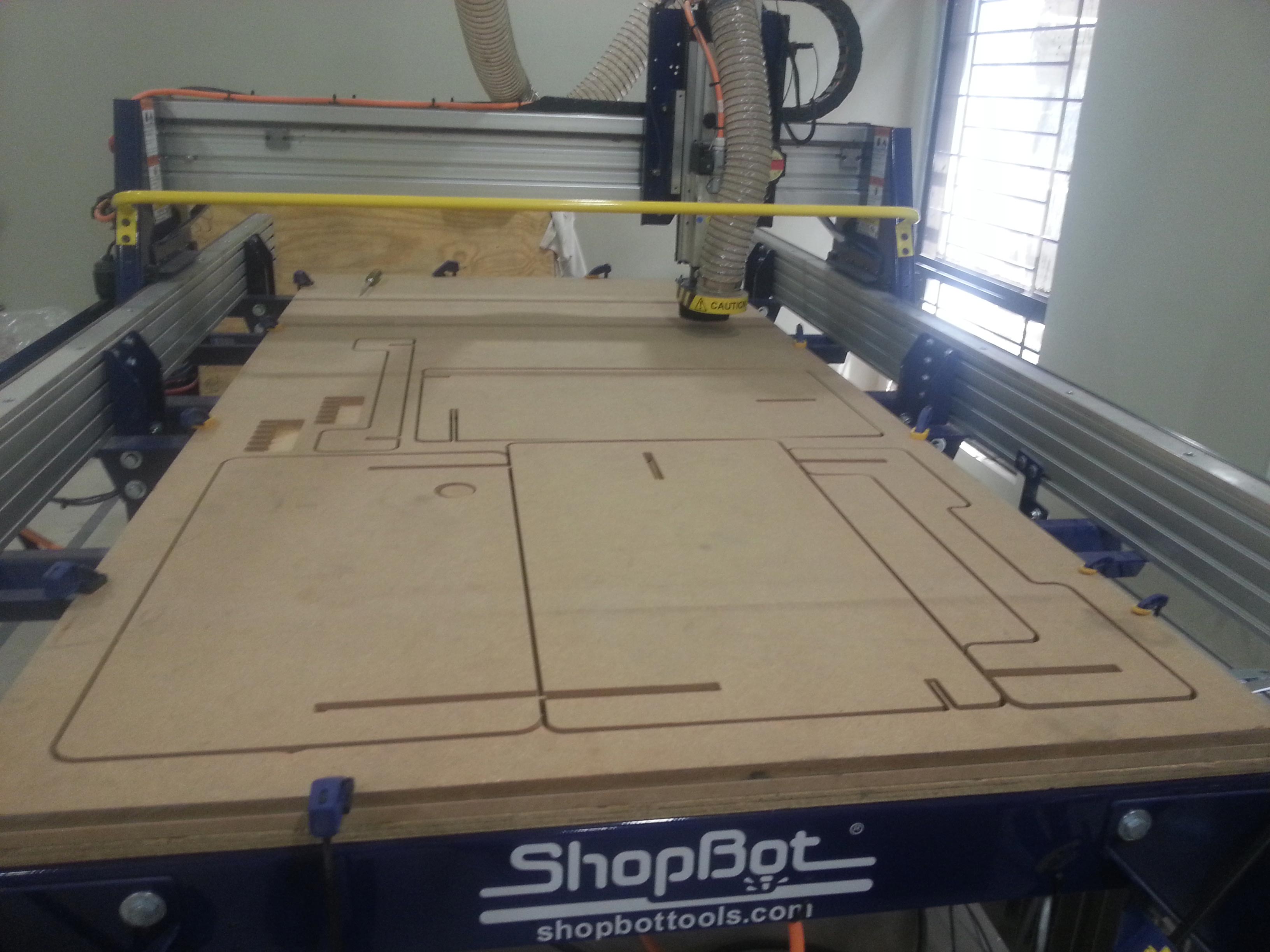
Flattening the Platform
Taking Measurements
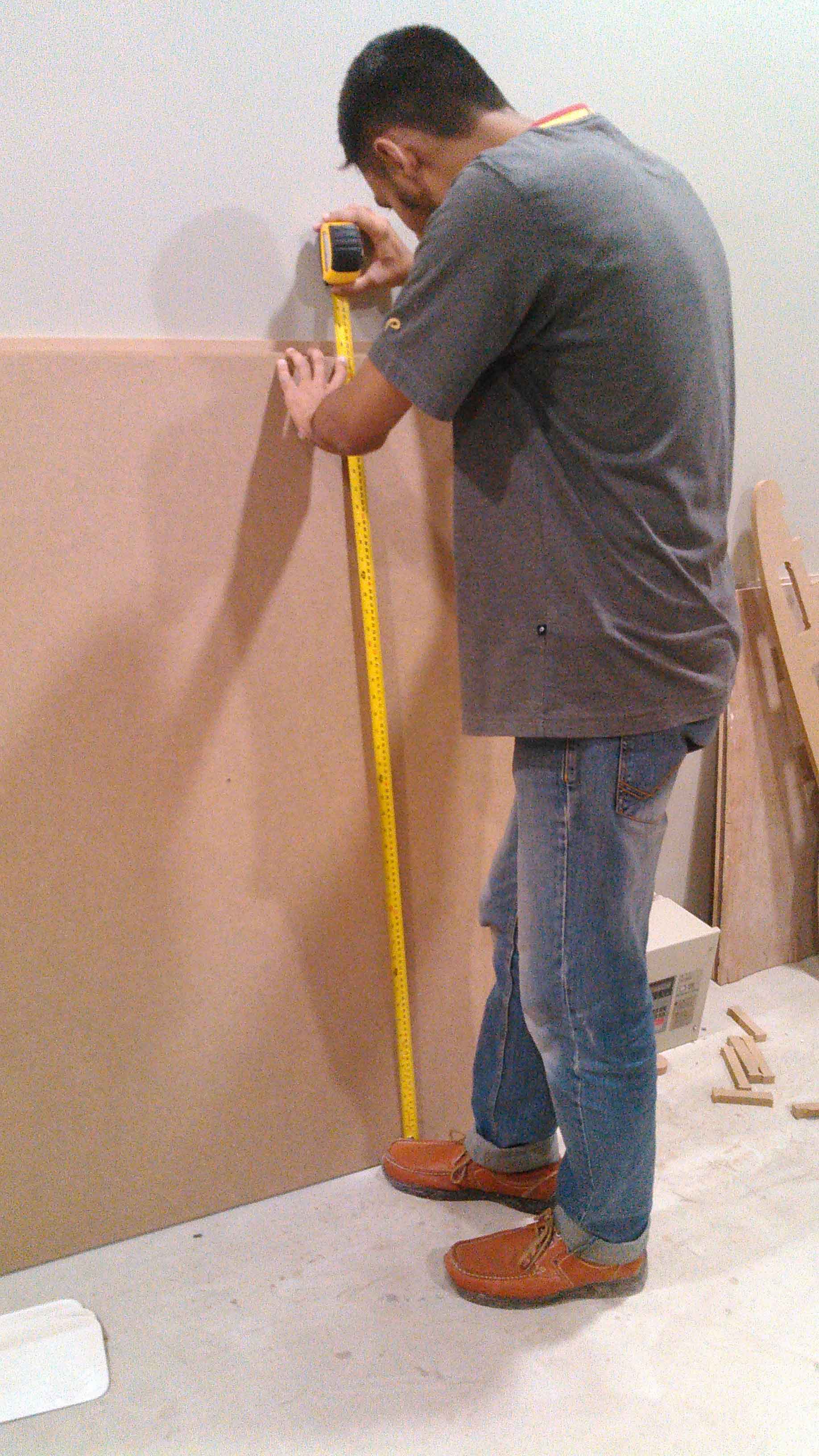
We are provided 8x4 ft 17mm MDF Wood boards for working on this week task,we use MDF board as platform for our Shopbot, but after checking the thickness we found that the board was not 17mm thick on each side.
Measuring thickness of board
We also measured height and width of the board because while creating toolpath we need to feed these input also
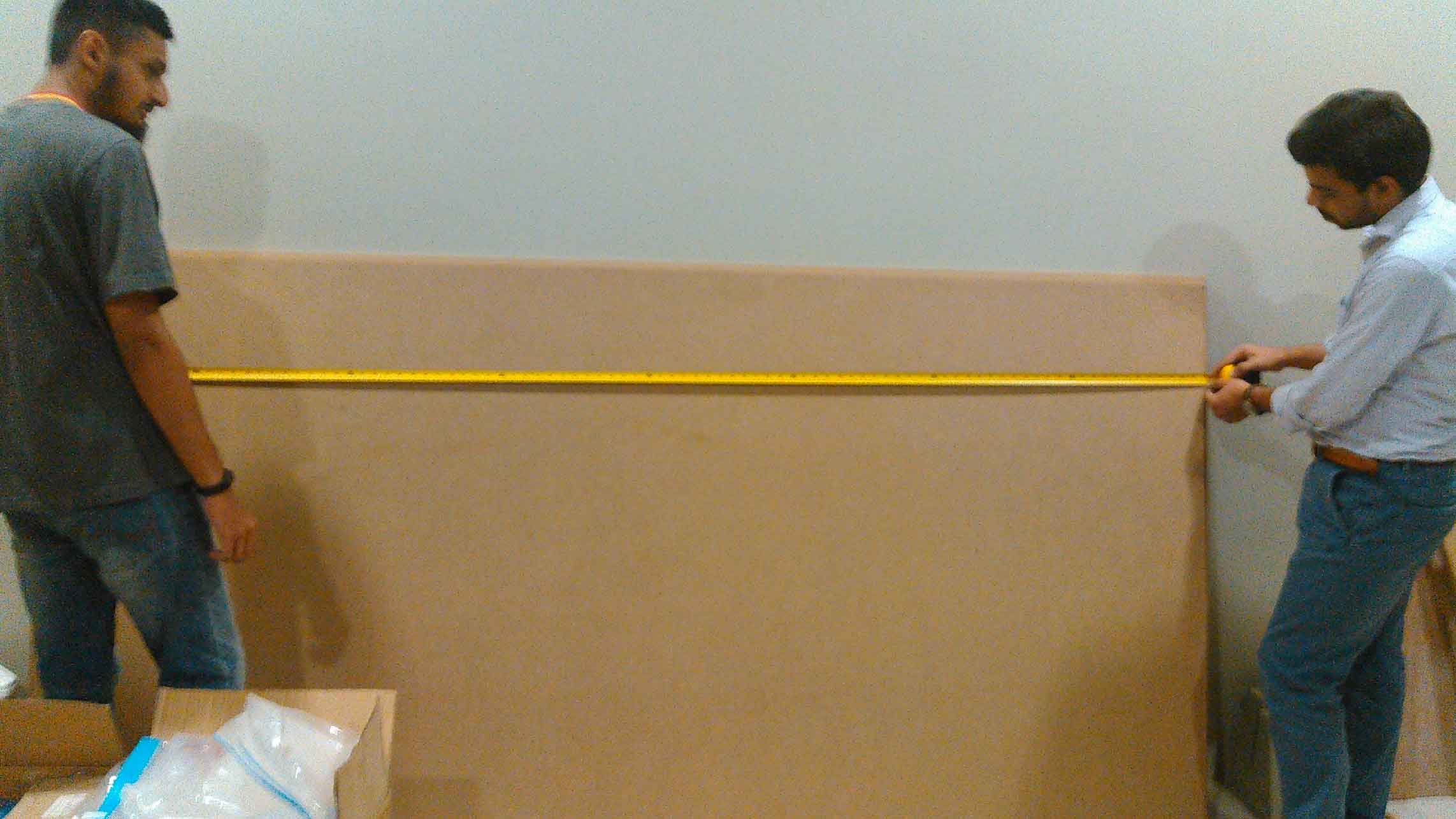
Taking board measurements
To make the surface flat we are using spoiler board cutter which shaves board to same thickness.
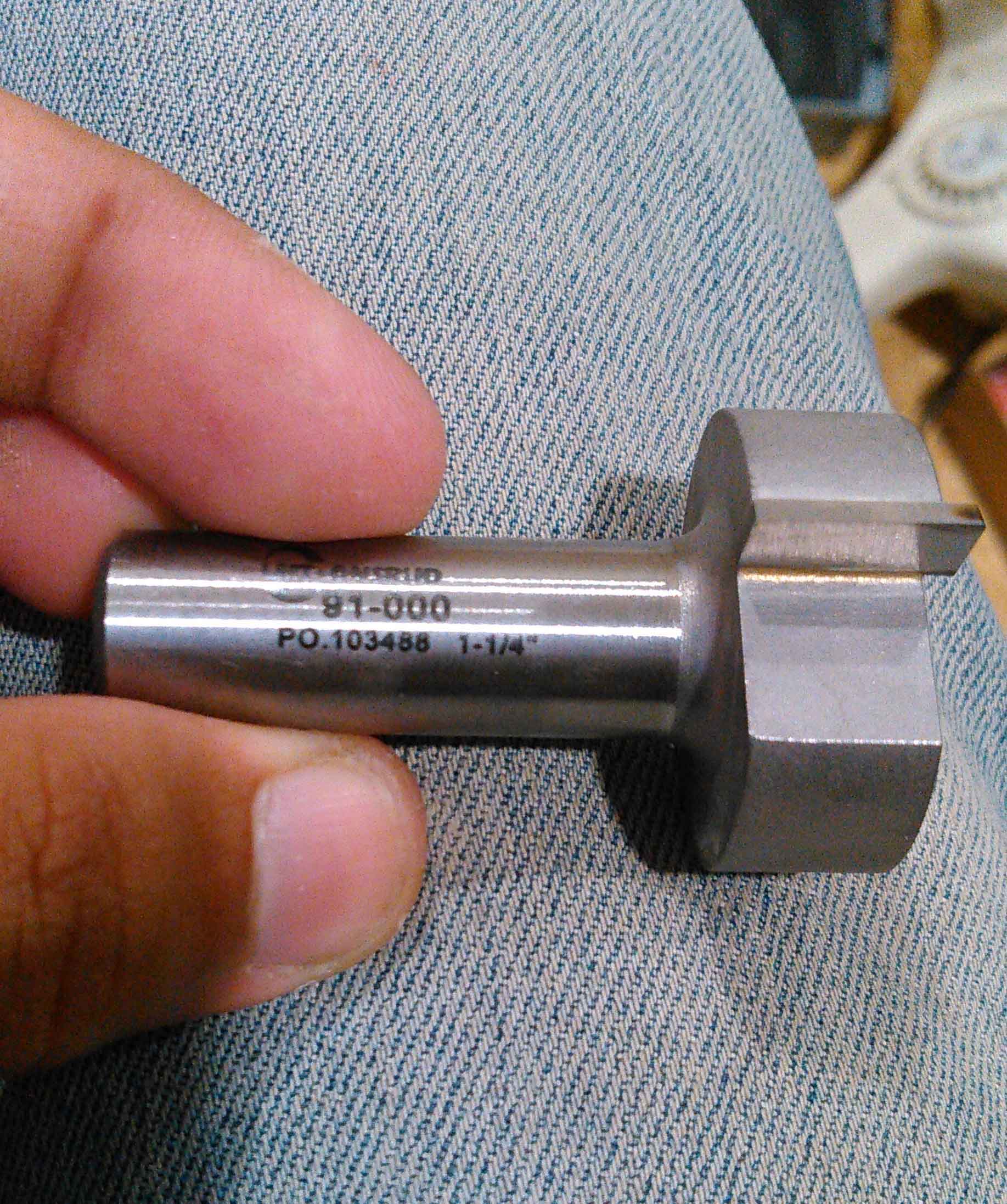
1/4" Spoiler-Board Cutter ( 91-000) Bit
Generating Toolpath:
We are using VCarve Pro Software to generate the G-Code for ShopBot, below we described each step for this process:
- Double click on VCarve to open it
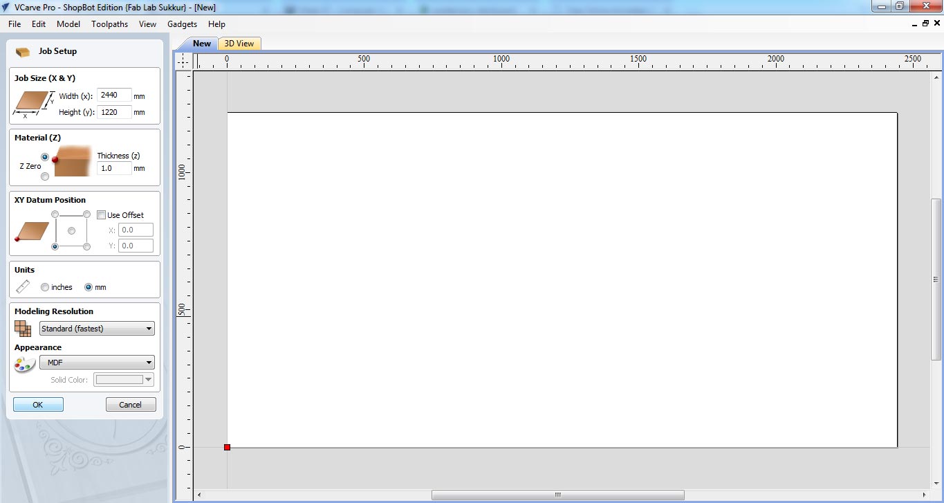
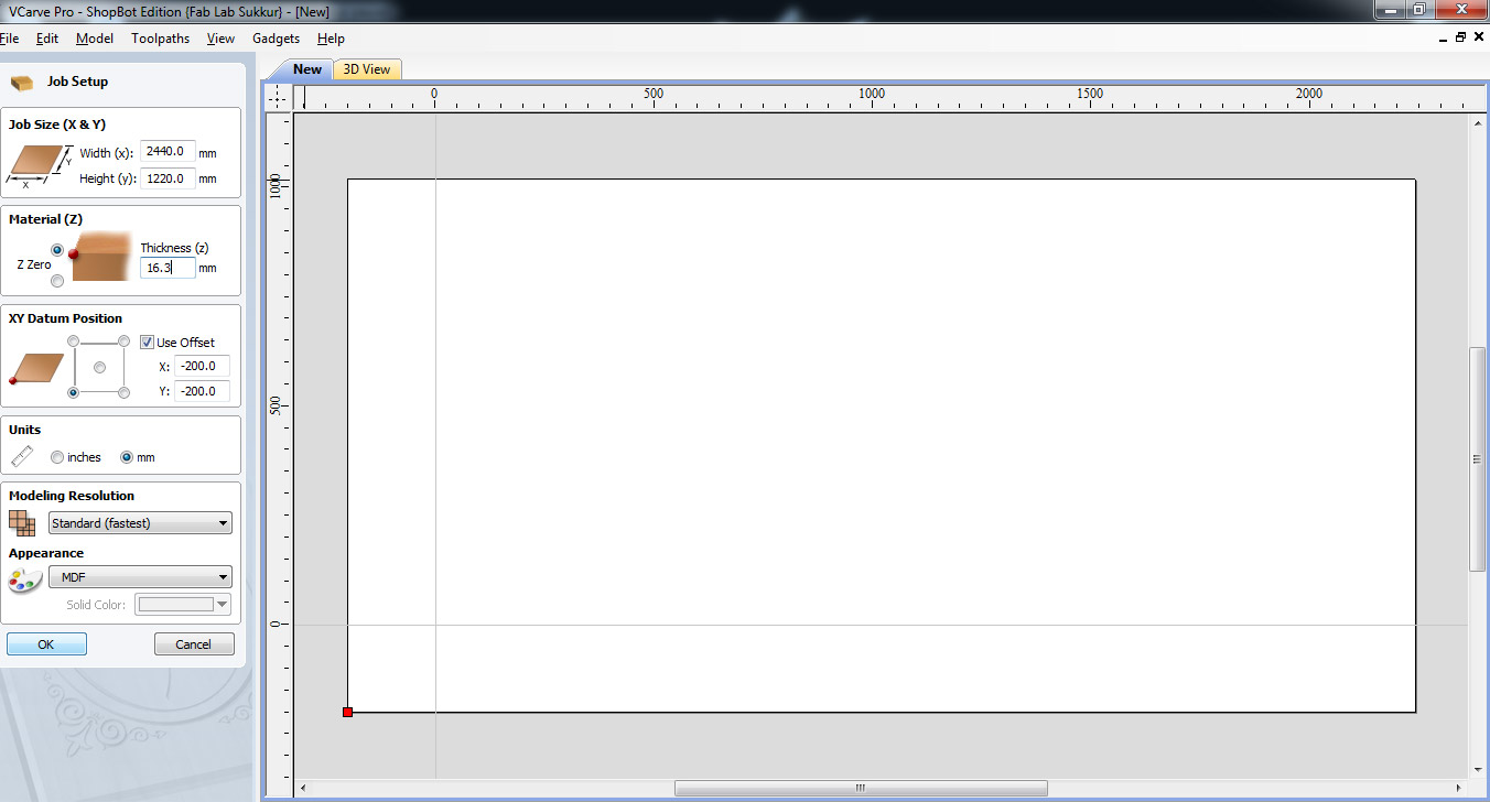
- Fill the job setup menu by entering board dimensions (width, height and thickness), set the XY Datum Position by clicking on bottom left corner, set units (our dxf files are in millimeter so we select "mm" in this column) and in last for appearence we select MDF because we are using MDF, then click "OK" for file operations.
- To generate a toolpath a vector is required, so we draw rectangle on whole board.
- after making vector now we are setting up the toolpath. Click on "Pocket toolpath" option in toolpath tab, then set the cut depth to "1mm" this shaves the whole board over 1mm, then select the "tool", in our case we select 1/4" Spoil-board cutter (the picture of the tool is mentioned above). Now select the vector, name the toolpath and click on "Calculate"
- After calculate the toolpath it is good practice to check the Preview of toolpath, if something is not shown right then change the settings and again generate toolpath.
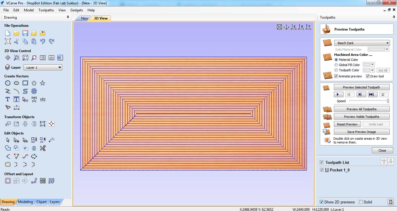
- If everything is correct in preview save the toolpath by checking post processor and set it to the dimensions we use to make the file. and then click on "Save Toolpath(s) to File", this can generate .sbp file which is used by ShopBot as instruction to work on job.
Generated .sbp file is given to shopbot, after setting x,y and z coordinates, we click on "Cut" in Shopbot panel to start the job
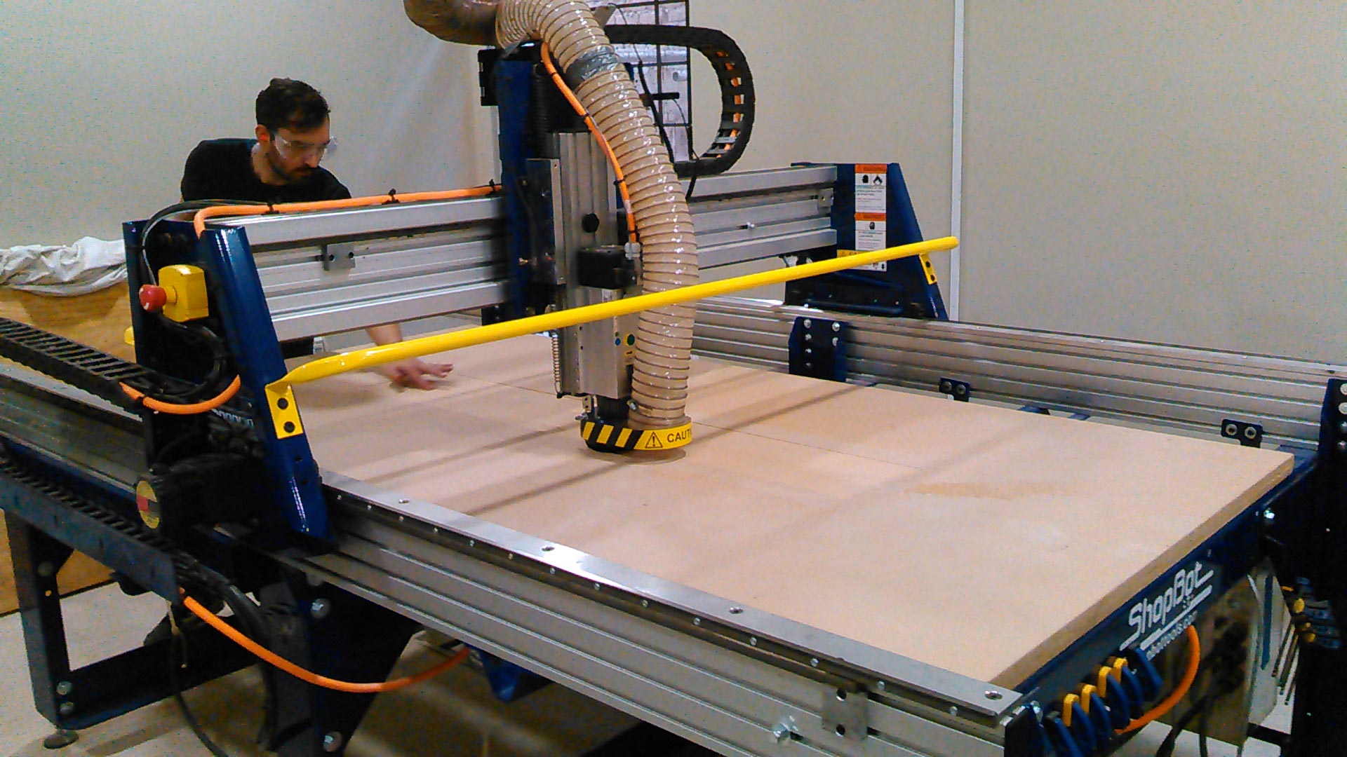
Mr. Francisco checking machine performace while machine is paused between surface flattening process.
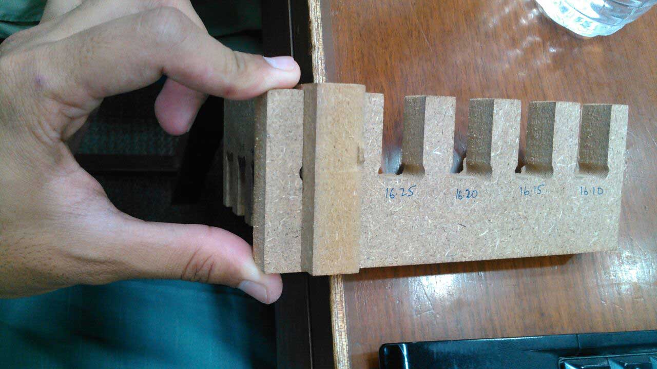
Making Test Part for Press-Fit
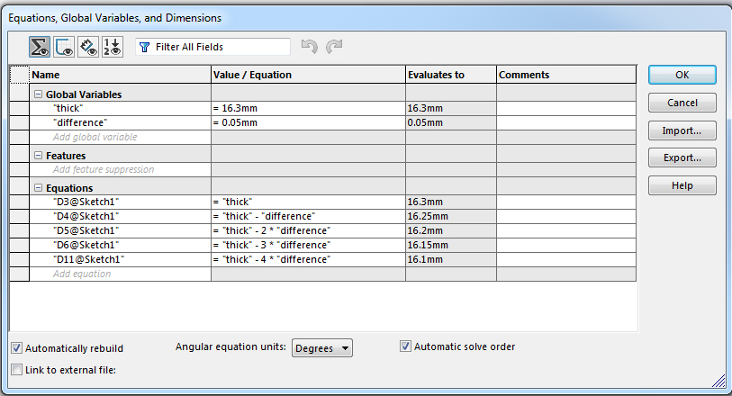
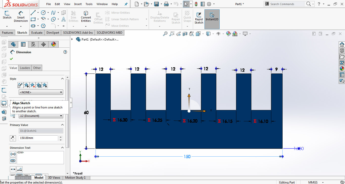
Most of our assignments are press fit so we made a test part with different thickness slots to check in which slot the wood is better press fit. The design is made in SolidWorks while using two parameters, one is average thickness of material and other is the "difference" which is used to set the slot sizes.
Using "Line" tool and "smart dimensions" we made this little piece of 60x150mm.
For VCarve we need a file in .dxf format and to make a dxf in Solidworks first we need to open the file in "drawing" window then save it as .dxf
After making test part design we are instructed to prepare our week assignments and set them along with test part in VCarve for job.
Individual Assignment
Make Something Big
This week is full of challenges for me, as electronic engineer I am new for 3D Modeling and this week we are going to push our limits to next level in 3-D designing and modeling by making something big. So for this week's individual task I decided to make a study table. While searching designs on internet I saw one design whose dimensions aren't mention but it was beautifully press fit by making boundaries (which I felt was missing in my study table) with the description "No glue, fastners, nails or screws required". I decided to change its design and make it to cover this week's task.
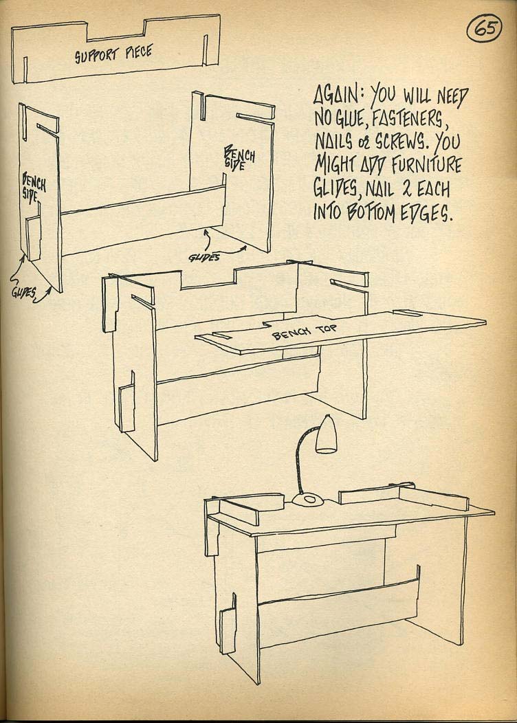
Here is the link of above image: Click here.
3D Designing
In Fab Academy we are always encouraged to work on new softwares. In past weeks I started 3D Modeling on SolidWorks, now I try one more 3D modeling software "Rhino 6" (got 90 days trial version). The software has some good features like it has 4 differnet views of 3d Model in a one screen. The software is bit difficult in starting but soon after some tutorials on youtube I got little grip on it, GrassHopper is a plugin to do parametric modeling in Rhino environment it is also good feature which I need more time to cover, so my first design I made on Rhino 6 but after that I again switched to solidworks
First Design using Rhino 6
To start designing, my only help for making the table is the design in picture which I shared above, the steps which I followed to make Design in Rhino is shared below:
- The design is based on 5 parts which combine to make a study table and all parts are drive from rectangle. For making a part first I make a rectangle
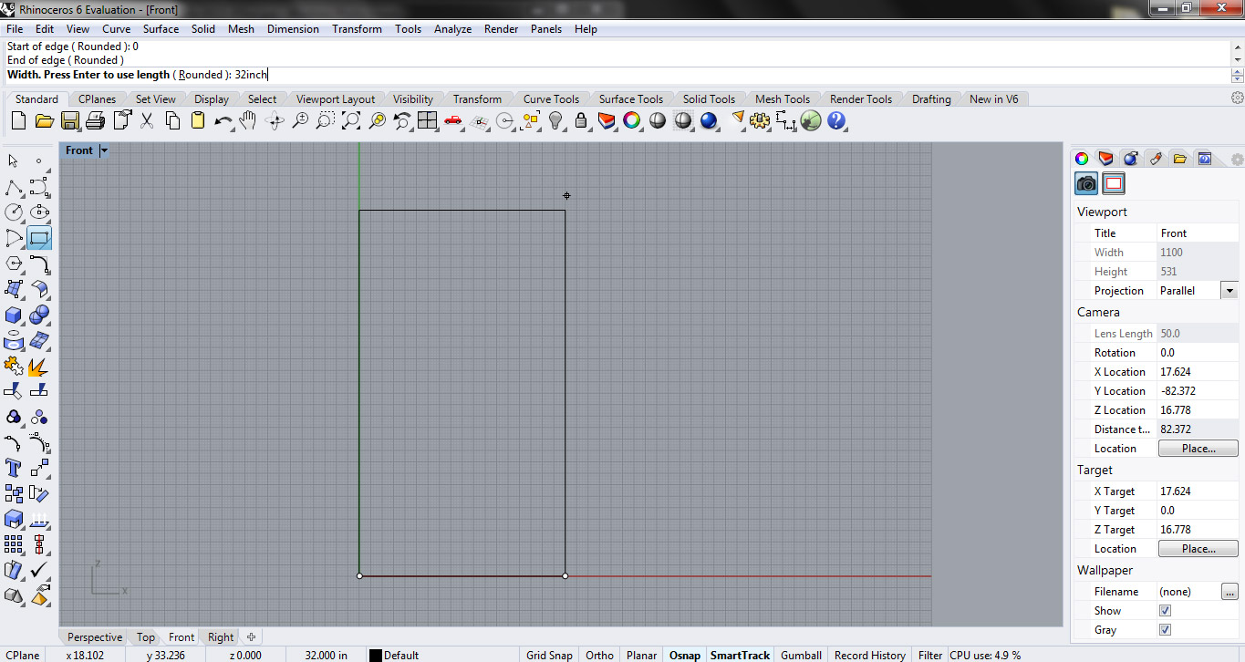
- After making rectangle I used polyline command to trace lines by giving dimensions on command box to make a desired shape, then I deleted the rectangle
- the shape is extruded using command "ExtrudeCrv" with respect to the thickness of the material, in my case I use 0.393 inch which is 10mm.
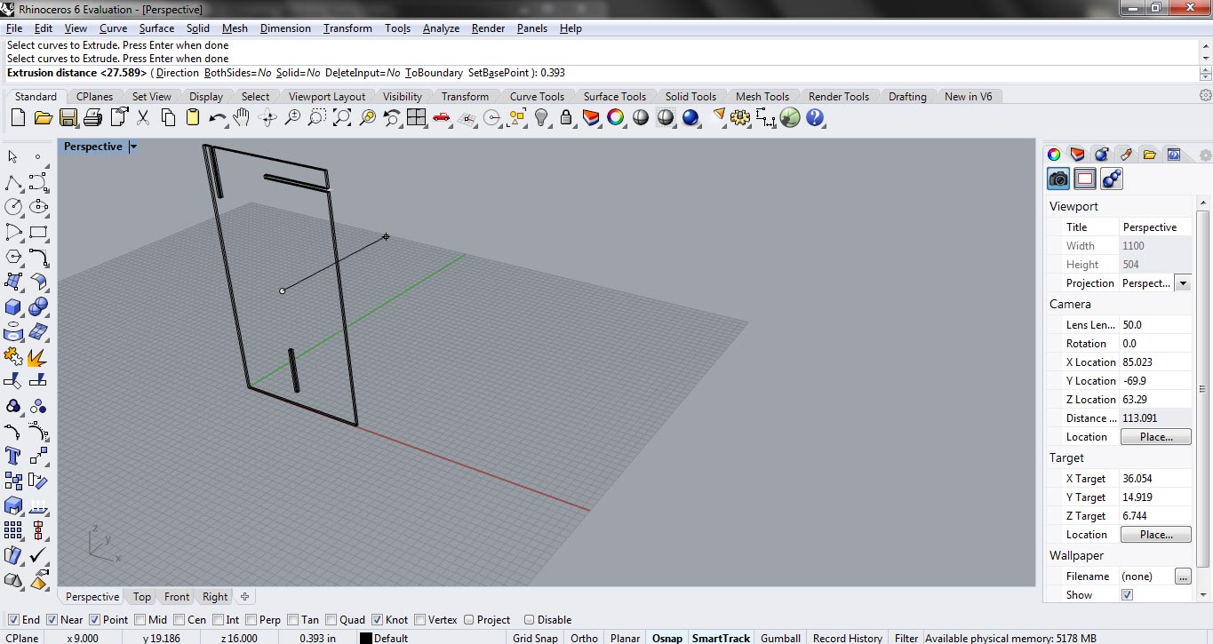
- using same method I made other parts as well:
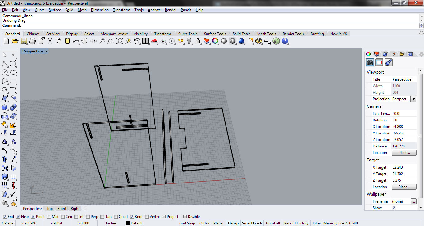
- now for testing the model we are going to laser cut the parts and for that I need to convert my 3D Model into 2D. I rotate all the parts to lie on top plane:
- after setting all the parts on top plane I export the file in svg to furthur work on Inkscape
- The image is scaled to 20 percent of original image. The lines for vector cut set to 0.001 inch others are by default set as raster, the file is save as pdf at 600dpi for Epilog laser cutting
- Here is the sample scaled size of my first design on cardboard, The design is looking goood but I made slits more longer than needed because of that If I press to fit more they are going more inward then needed
Second Design using SolidWorks
We are not bounded to use one software so I make this design in SolidWorks, my first design was very simple so in this attempt to make my study table look more cool I make some changes in it.
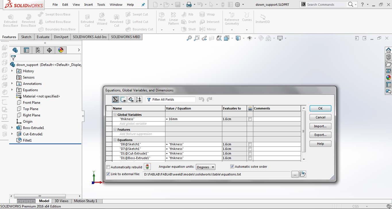
- In Solidworks before starting to design I set global variable "thickness" to 16mm, so whenever there is a change in thickness my design easily change with respect to that.
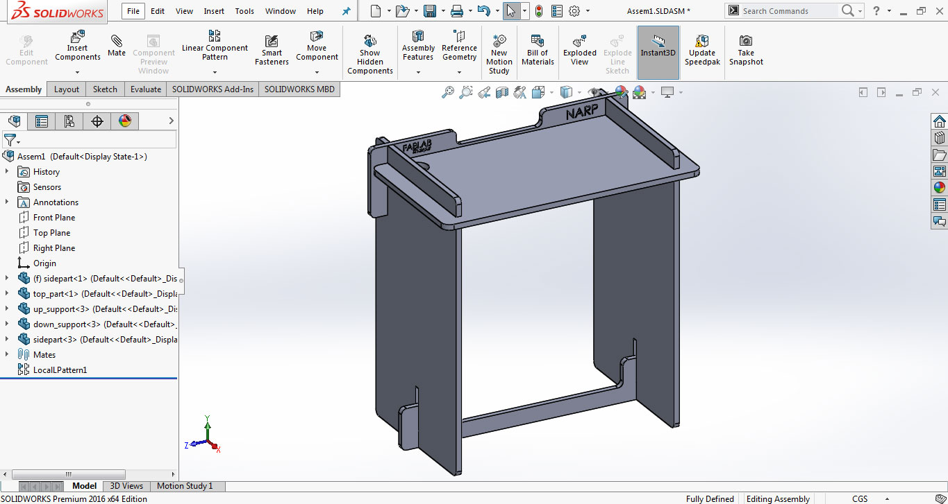
- I made each part individually in Solid Works and then assemble them using "Mate" to check either the parts fitted perfectly or not in Assembly tab.
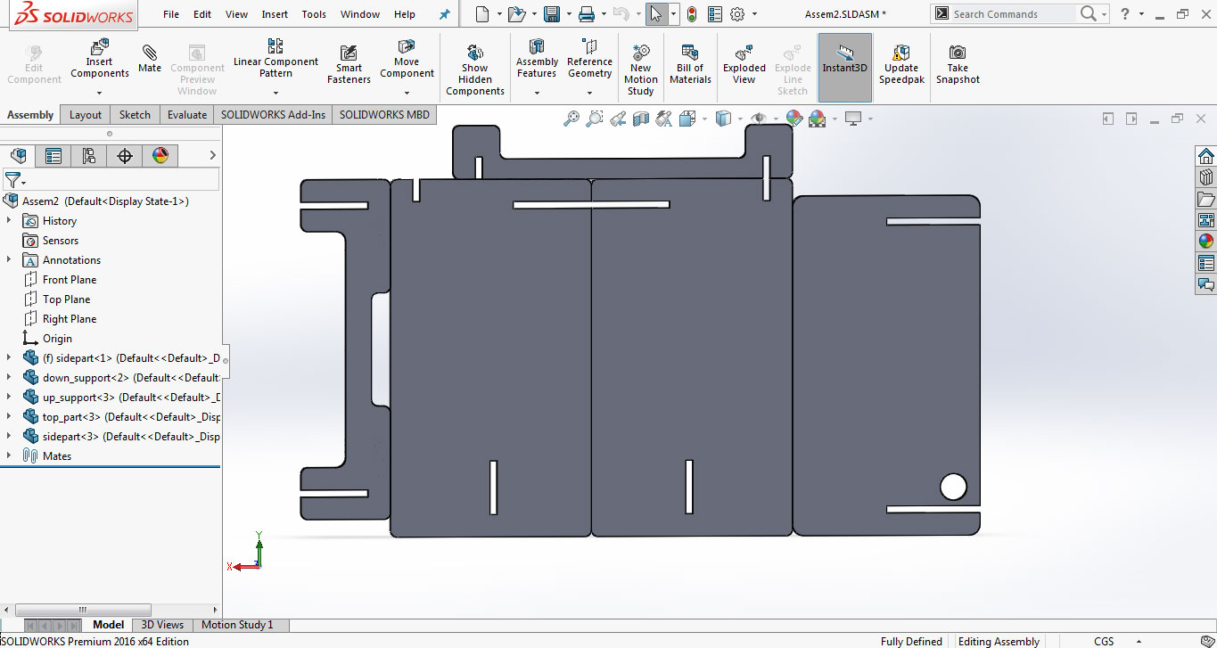
- After checking the parts perfectly fitted in assembly I need to make 2D Design for laser cut of it, for 2D Design we open one more assemble tab and set all the parts in front plane, joining each part boundary with other using "Mate".
- after completing the 2nd assemble document now to open this file in drawing document and save as .ai format for working in InkScape, the steps on drawing document is shown below:
- The generated .ai file is opened in InkScape and scaled to 25 percent of original size, this can set slit parts to 4mm thick material as we use 4mm cardboard to try a sample for this design. a pdf is generated using same method as we use in first design for laser cutting process in Epilog Laser Cutting machine
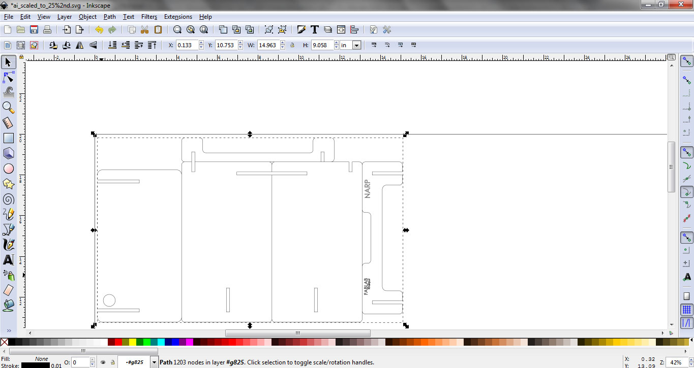
- The scaled design on 4mm cardboard is displayed below, it has some losing in press fit parts because of cardboard which is not 4mm thick from all sides. Other design is good for proceed to shopbot. :)
Setting Up File for VCarve
For ShopBot we need to make the dogbones in the files so drill can move in corners as well otherwise drill leave the corners in slope shape. I made the dog bones at all corners where needed in my parts
Making dogbones in Solidworks
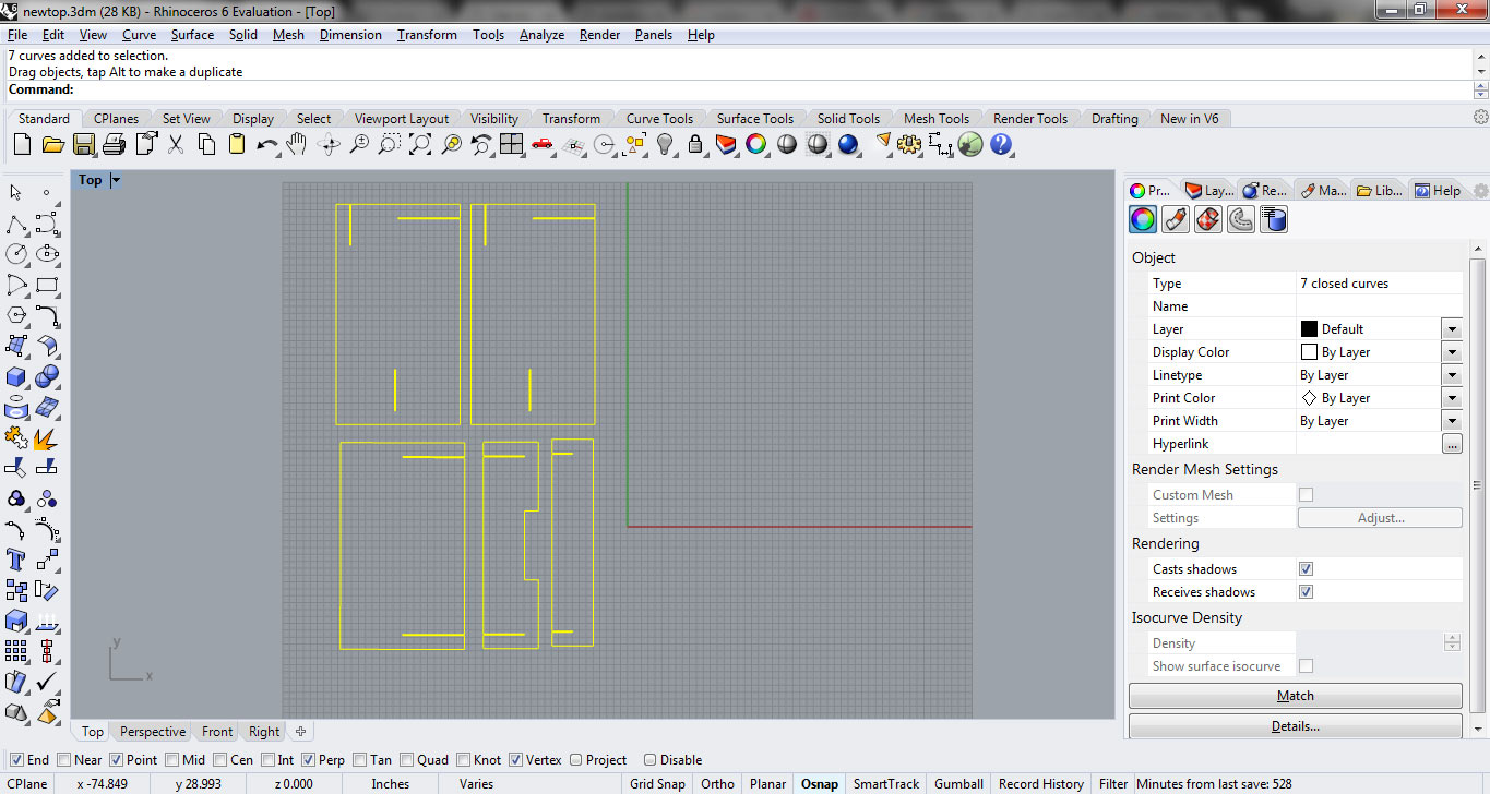
Unlike laser cutting machine I need to seperate the parts in the file because in shopbot we have option to move drill bit on vector, inside vector and outside vector. So I seperate the parts in the file by "unmating" them, then open file in drawing file and save as .dxf for VCarve process
Setting Up File in VCarve
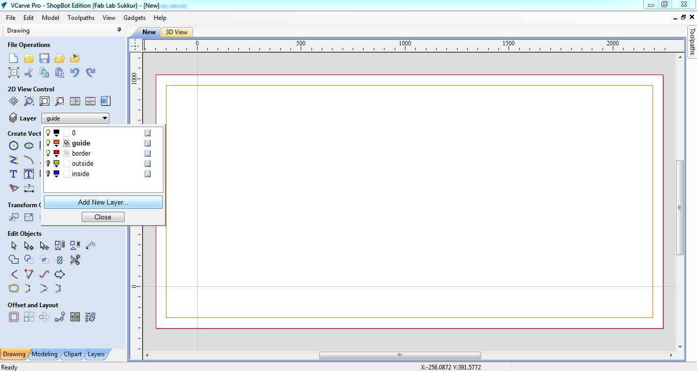
Bofore cutting test part and individual assignment we made some layers in VCarve, which help us to maintain the XY coordinates in case if we stop the machine and some how its coordinates changes. Second the guided layers help us to prevent the machine from accidents.
- First we set the MDF board size and thickness,and use offset -200 in both X and Y direction, this will be our guide to zero the XY positions.
- Then we make a guide layer to leave space of 50mm from each side and make a border layer to mention boundaries
- Then we make two more layers one to set inside cuts and other is for ouside cuts, this can distinguish both the cuts and help to generate the toolpaths seperately
- After making layers now I opened my .dxf file of individual assignment in VCarve. I shift all the outside cuts to outside layer and inside cut to inside layer then rearrange them so they take less space on board
- Then I opened test part, copy it and set them in suitable empty space, next step is to generate toolpath now we need to cut the boundaries of the parts so we are using the profile toolpath
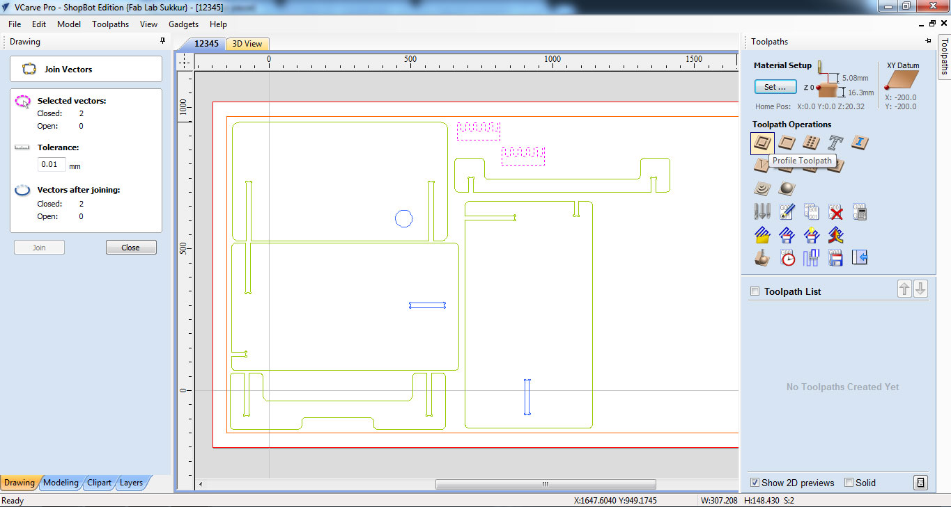
- In toolpath settings we set Cut Depth as 16.3mm, Set Machine to run outside vectors, selected 1/4" Down-cut (57-910) drill bit and add tabs which help part to not move from place while cutting and then checked preview
- After making test parts I changed the value of Cut Depth to 17.3mm and thickness of tab to 3.2mm because we learn in test part, that a platform is not accurately 16.3mm thick and the test part was not perfectly cutted (the pictures of test part is shown below in next section). Other things remain same and I made the toolpath of both inside and outside layers by selecting machine run to outside and inside respectively.
The generated toolpaths will be save as .sbp (the method is disscussed above in group assignment) and then .sbp files given to shopbot to done the job.
DownCut drill bit which we used to cut the 16-17mm thick MDF
Cutting and Removing
After cutting test part we understand that the material which we are using for assignment is not thick uniformly and for better results we should have to cut in more depth
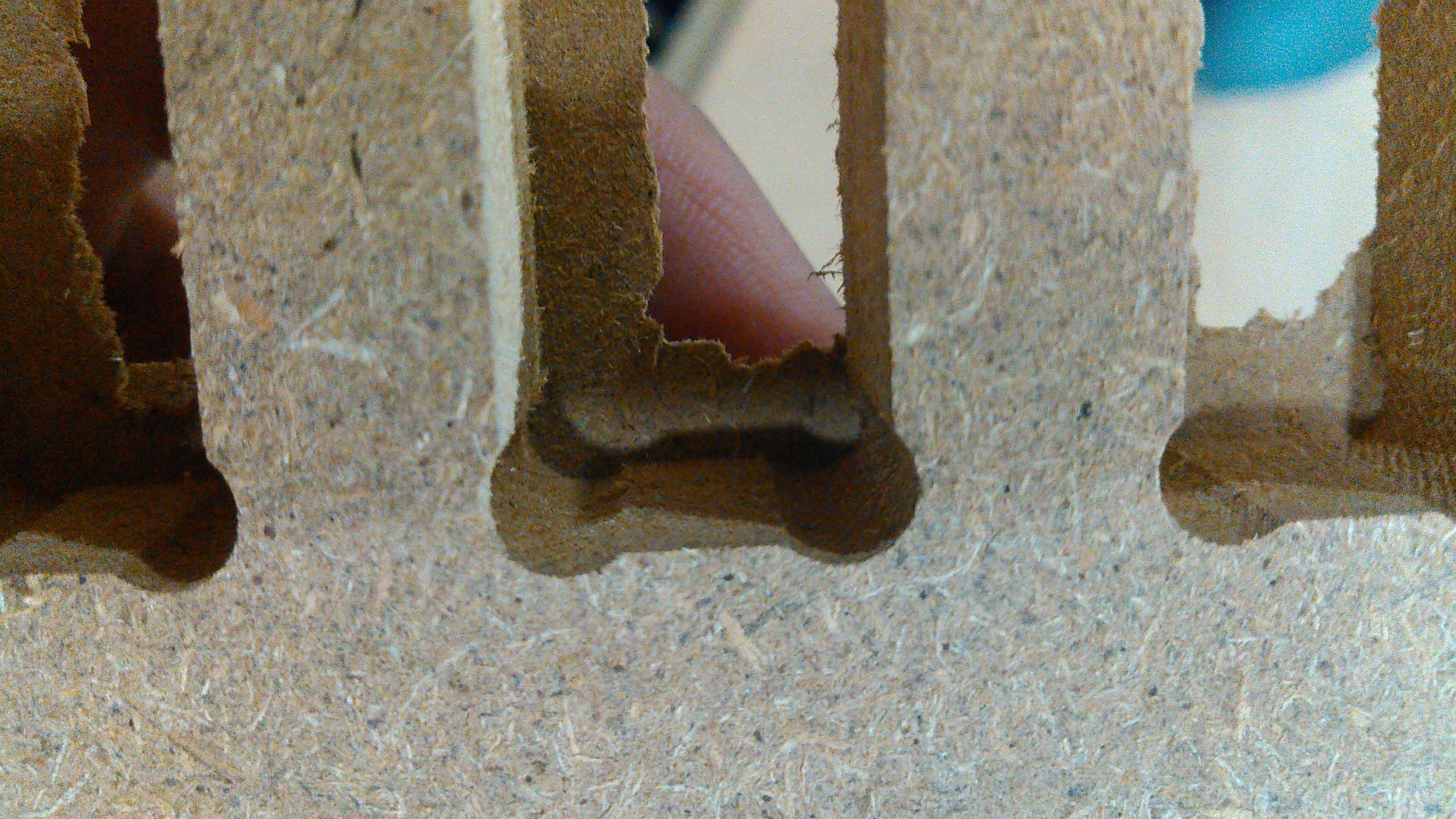
Last mm layer was not cutted perfectly
Test part perfectly fitted in 16.3mm slot
Test part press fitted
Parts of my study table cutted by ShopBot
I removed tabs after cutting of my assignment using hammer, big screw driver and a little bit force. It is good to remember where the tabs are otherwise just drag the screw driver between gaps and when you get the block hammer it.
Removing tabs
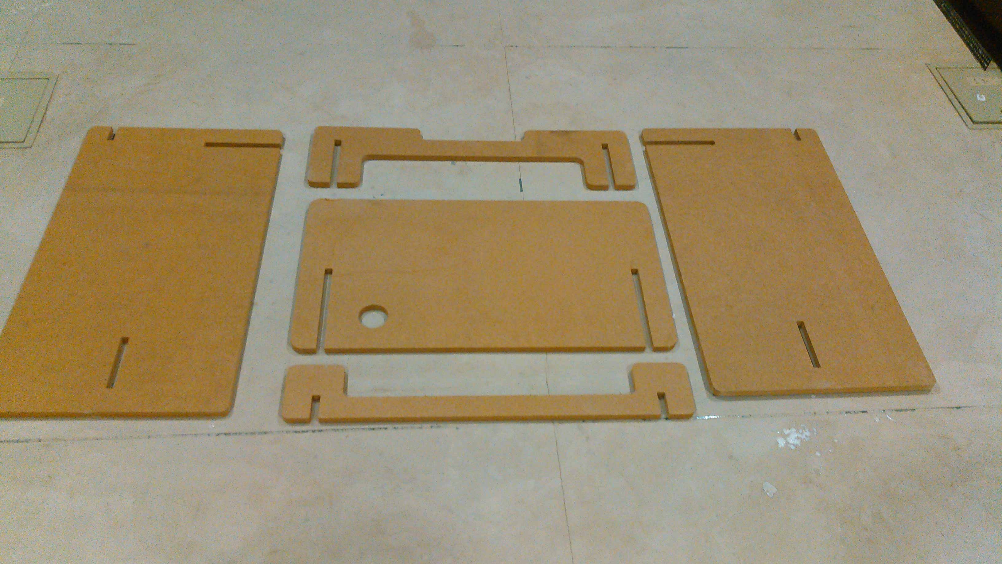
The parts are ready to assemble process
Assembling Process
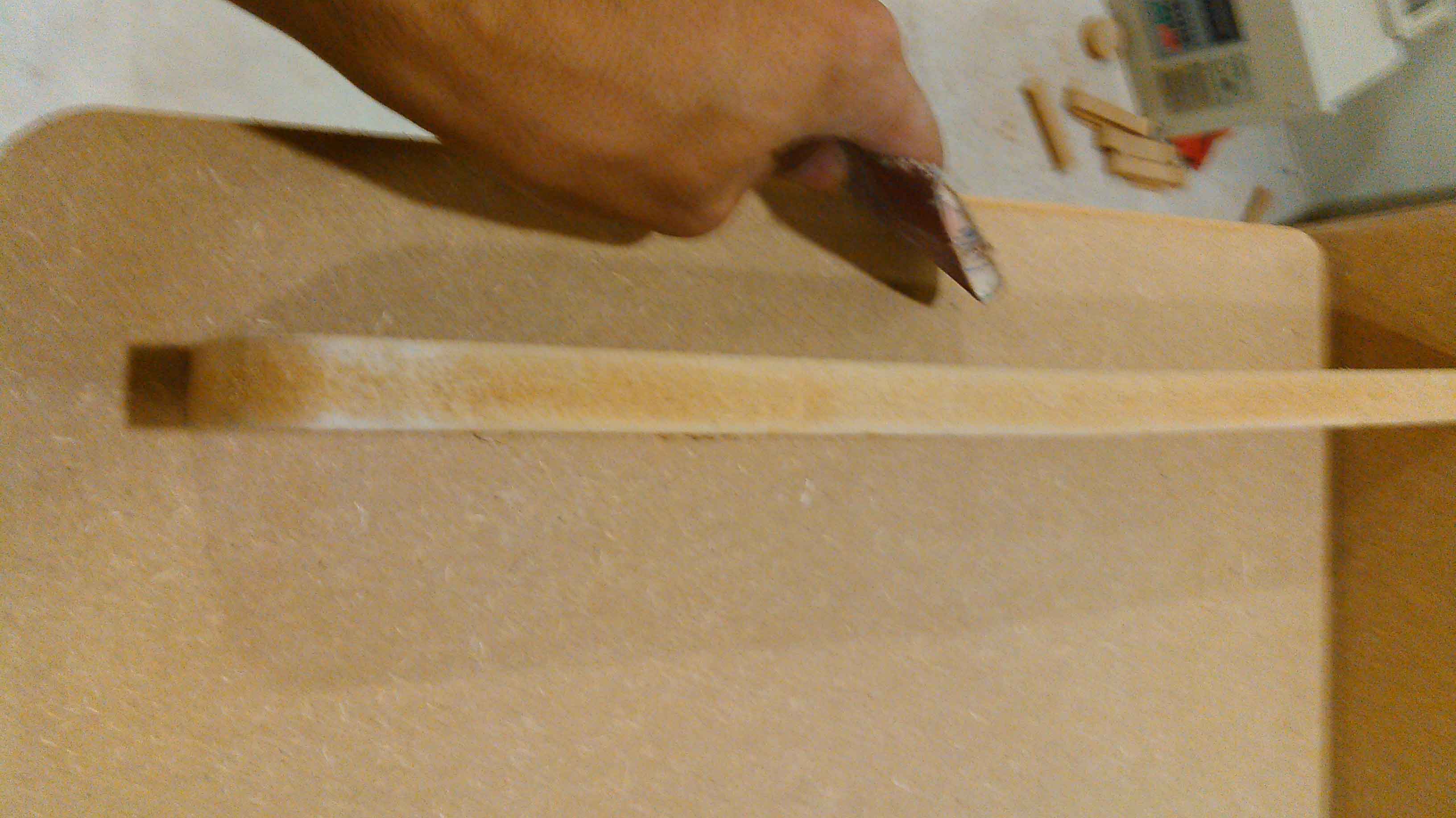
This is my first time to make something like this and I totally miscalculated it. I make the press fit slot by measuring the dimension of the other slot which is going to fit in my imagination. When I try to joined them the slots are perfectly fitted but with respect to my table design a slot should be fixed in a wood which starts after opposite slot.
miscalulation of nearly 1.5mm in design
I wide the slots using file and then use sandpaper to smooth surfaces
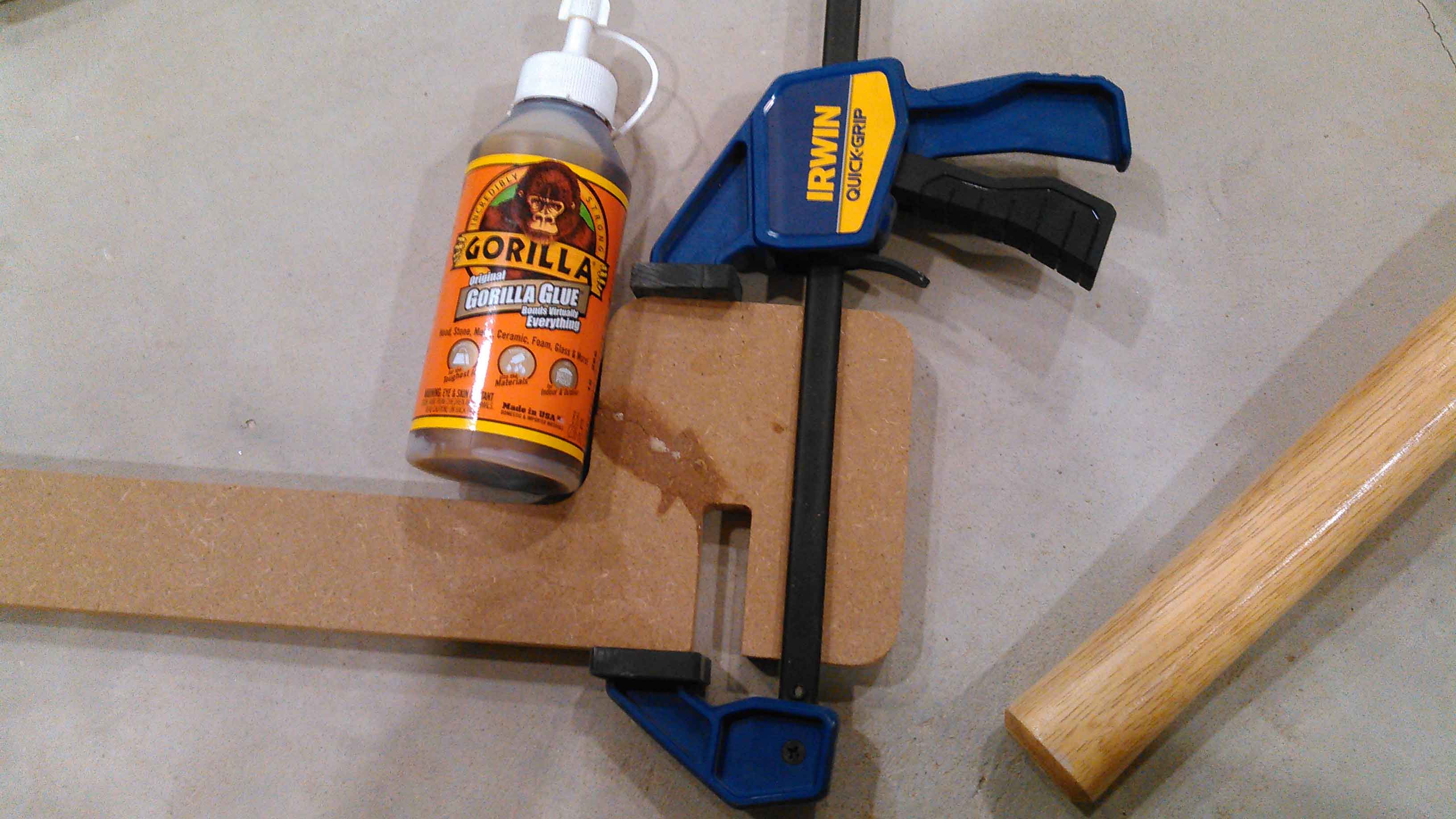
While press fitting one peice is broke by applying extra force. But thanks to Gorilla glue it is fitted perfectly
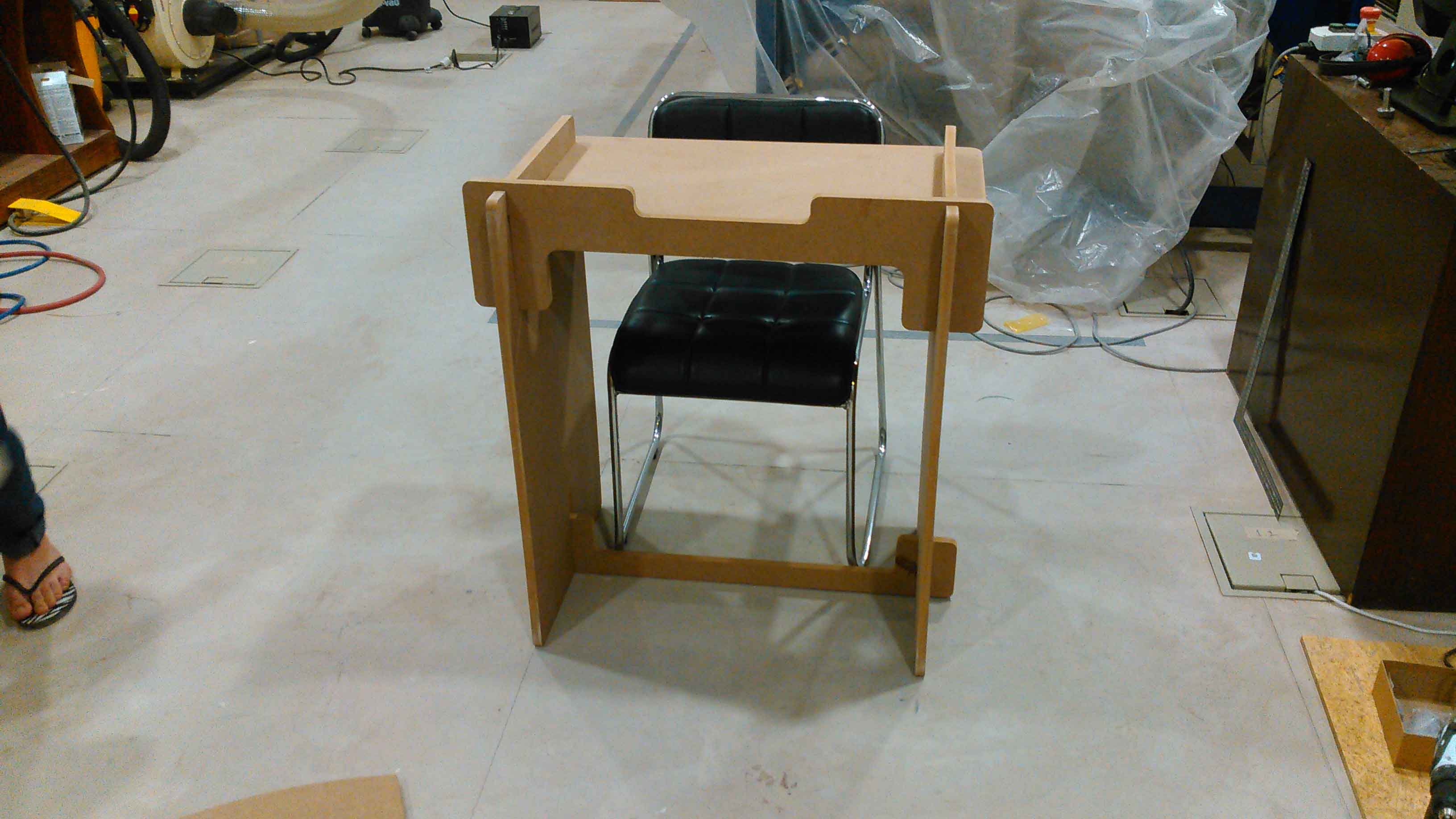
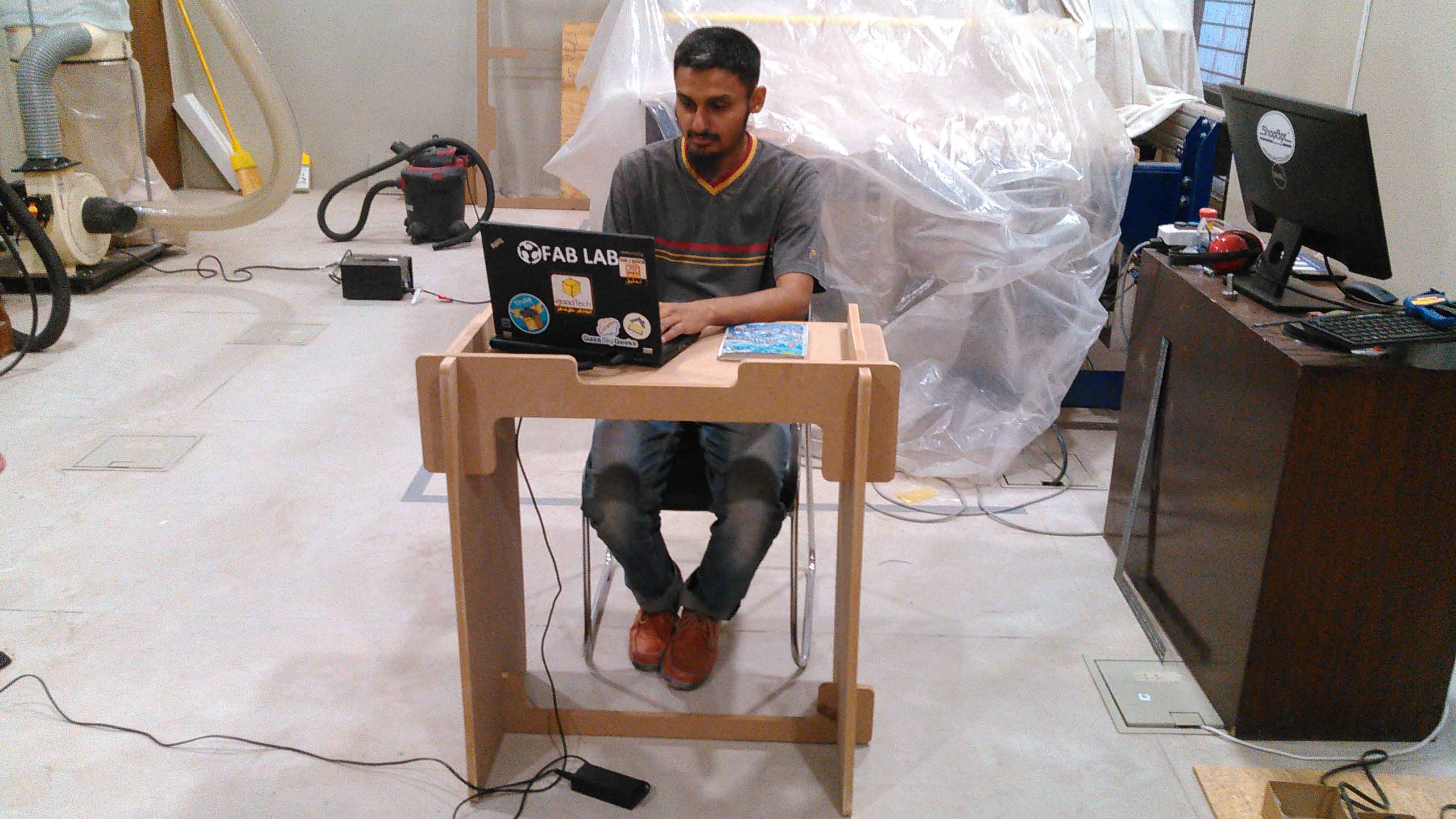
After all the hurdles and problems finally I press-fit my table and the result was awsome
Acknowledgement
This week is specially dedicated to our guest Mr.Francisco Sanchez who visited Pakistan, repaired the ShopBot so we complete this week assignments, and taught us many many things in his very short visit.
"Click here"to download all files of this week

This work is licensed under a Creative Commons Attribution-NonCommercial 4.0 International License