WEEK-9
Embedded Programming
Lecture & Recitaton of a Week:
Lecture on 14th of March, 2018: Embedded Programming by Neil Gershenfeld
Recitation on 19th of March, 2018: safety and security by Patrick Colgan and Joel Gershenfeld
Tasks for a Week
- individual assignment: read a microcontroller data sheet program your board to do something, with as many different programming languages and programming environments as possible
- group assignment: compare the performance and development workflows for other architectures
Individual Assignments
What is Datasheet
From Wikipedia: datasheet, data sheet, or spec sheet is a document that summarizes the performance and other technical characteristics of a product, machine, component (e.g., an electronic component), material, a subsystem (e.g., a power supply) or software in sufficient detail to be used by a design engineer to integrate the component into a system. Typically, a datasheet is created by the component/subsystem/software manufacturer and begins with an introductory page describing the rest of the document, followed by listings of specific characteristics, with further information on the connectivity of the devices. In cases where there is relevant source code to include, it is usually attached near the end of the document or separated into another file.
Reading Datasheet
Below I am sharing relevant information about ATtiny44 because I used that IC in my board and I am going to program it in this week.
Features
First page of every datasheet is based on key features, it is like a review page which describes either a device is useful for specific work or not. I am sharing some of the features below
- High Performance, Low Power AVR® 8-bit Microcontroller (8 bit microcontroller is a self-contained system with memory, a processor and peripherals that can be used as an embedded system)
- Advanced RISC Architecture (RISC: Reduced Instruction Set Computer is a type of architecture for instruction set)
- 120 Powerful Instructions – Most Single Clock Cycle Execution
- 32 x 8 General Purpose Working Registers
- Fully Static Operation
- High Endurance, Non-volatile Memory Segments
- 2K/4K/8K Bytes of In-System, Self-programmable Flash Program Memory
- Endurance: 10,000 Write/Erase Cycles
- 128/256/512 Bytes of In-System Programmable EEPROM
- Endurance: 100,000 Write/Erase Cycles
- 128/256/512 Bytes of Internal SRAM
- Data Retention: 20 years at 85°C / 100 years at 25°C
- Programming Lock for Self-programming Flash & EEPROM Data Security
- Peripheral Features
- One 8-bit and One 16-bit Timer/Counter with Two PWM Channels, Each
- 10-bit ADC
- 8 Single-ended Channels
- 12 Differential ADC Channel Pairs with Programmable Gain (1x / 20x)
- Programmable Watchdog Timer with Separate On-chip Oscillator
- On-chip Analog Comparator
- Universal Serial Interface
- Special Microcontroller Features
- debugWIRE On-chip Debug System
- In-System Programmable via SPI Port
- Internal and External Interrupt Sources
- Pin Change Interrupt on 12 Pins
- Low Power Idle, ADC Noise Reduction, Standby and Power-down Modes
- Enhanced Power-on Reset Circuit
- Programmable Brown-out Detection Circuit with Software Disable Function
- Internal Calibrated Oscillator
- On-chip Temperature Sensor
- I/O and Packages
- Available in 20-pin QFN/MLF/VQFN, 14-pin SOIC, 14-pin PDIP and 15-ball UFBGA
- Twelve Programmable I/O Lines
- Operating Voltage:
- 1.8 – 5.5V
- Speed Grade:
- 0 – 4 MHz @ 1.8 – 5.5V
- 0 – 10 MHz @ 2.7 – 5.5V
- 0 – 20 MHz @ 4.5 – 5.5V
- Industrial Temperature Range: -40°C to +85°C
- Low Power Consumption
- Active Mode:
- 210 µA at 1.8V and 1 MHz
- Idle Mode:
- 33 µA at 1.8V and 1 MHz
- Power-down Mode:
- 0.1 µA at 1.8V and 25°C
Pin Configurations
This section have an information about pins of different packages. I used SOIC package in my board, here is the picture of pin configuration of SOIC package:

ATtiny44 Pin Configuration
Block Diagram of Internal Structure
The block diagram mentioned in "Overview" section defines the internal structure of IC, it shows how 8 bit Databus is connected with different parts of IC. This can help to understand the IC system and make it easy for programmer to pass set of instructions.
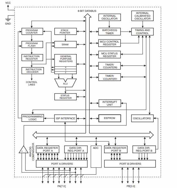
Block Diagram of IC internal structure
A microcontroller is a vast thing with lots of feature in it. A person can read and understand only those parts of datasheet which is helpful in specific work/project. There are lots of sections in datasheets which I like to learn but they can be understand easily when we have to use it with some kind of application. I have little knowledge of timer/counter section and want to learn more about it. These are some very basic and important information I shared. If someone want to read all about ATTiny44 then click here to download datasheet
Programming hello world board
I didn't practice my programming skills frequently after passing Bachelors, so in start it is difficult for me to work on that but I hope I get grip on programming skills sooner. For this week and for again start in programming I decide to work on Arduino IDE and ATMEL studio to program the hello world board which I made in week-7 Electronics Design. I burn the bootloader in my board on week-7 (as extra work) using my colleague laptop but in this week when I start to work on my laptop I experienced many problems because of mismatching of versions of avrdude. I am using my fabISP to upload the code in my board, I made fabISP in Week-5 Electronic Production.
Using Arduino IDE
There are lots of problem I face in this week and most of the problems only occur in my laptop. I found reasons, try to overcome them and because of too much time I spent in debugging this week I able to document this week in my week-14. Below I mentioned steps to work in arduino IDE along with the problems which I face while working.
- After installing arduino IDE, first thing is to connect the FabISP with PC. When I connect I got error that "USB Device Not Recognized"
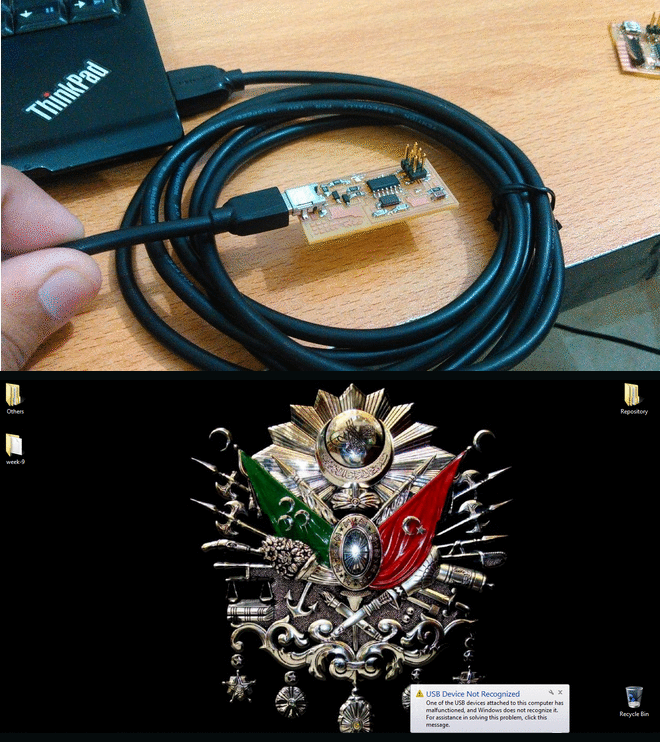
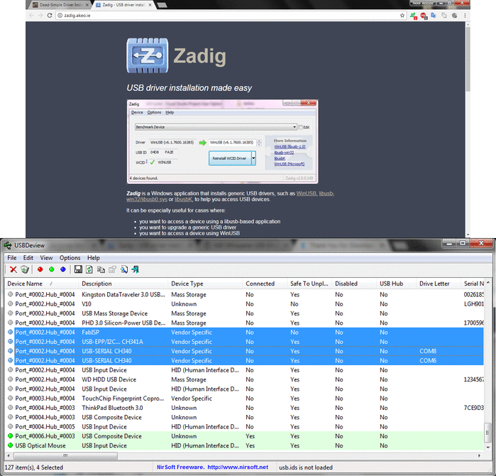
- First I taught that maybe the driver is used by some other program as I remembered that I override "libusb-win32" drivers for my chineese brand laser cutting machine to work with "k40 whisperer" software. I tried many things to redo that step by using Zadig and USBDeview but in result I deleted some important drivers of my operating system which leads to reinstall Windows and all the stuff.
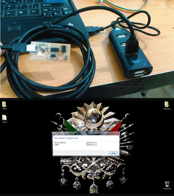
- I understands the problem after so many tries that my PC cut off the connection with FabISP because of power consumption of a board and for safety PC didn't connect with the device directly so I connect it to external USB hub and then connect external hub with my PC.
- Hello World board is based on ATtiny44 controller and to programm ATTiny44 using arduino IDE first I need to install the board in it.
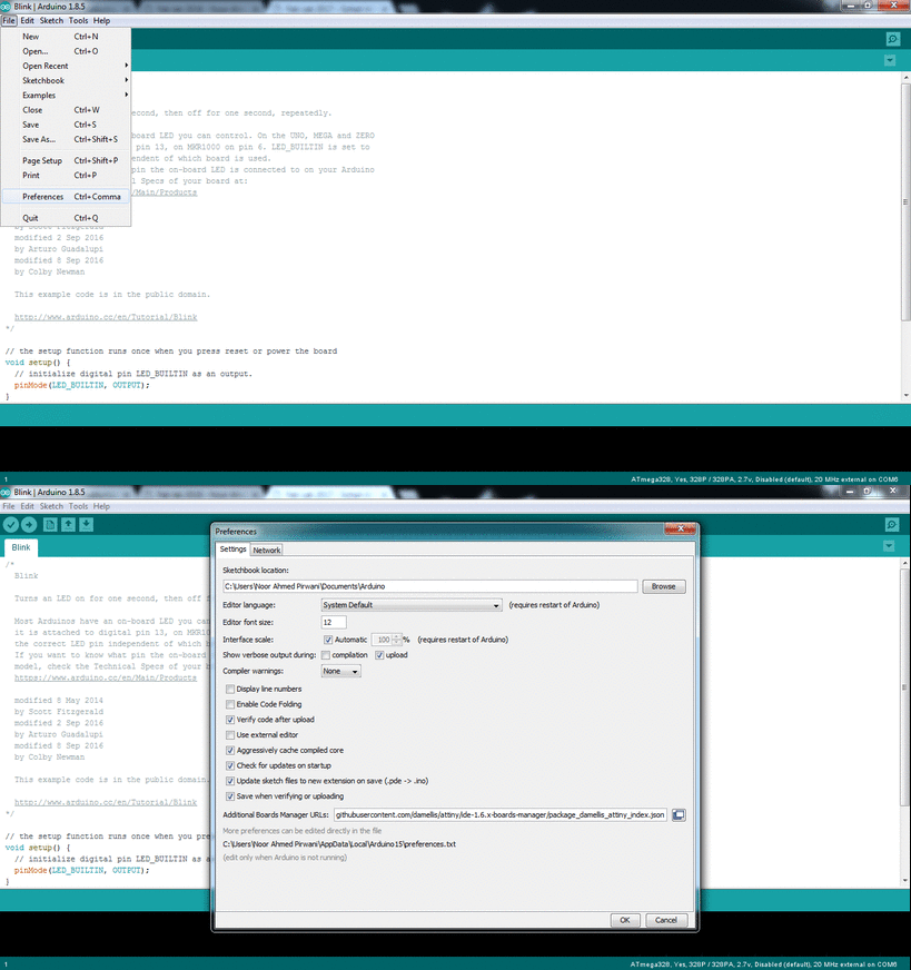
- I enter URL of ATtiny44 board in the Additional Board URL manager which is in File> Preferences. URL: "https://raw.githubusercontent.com/damellis/attiny/ide-1.6.x-boards-manager/package_damellis_attiny_index.json"
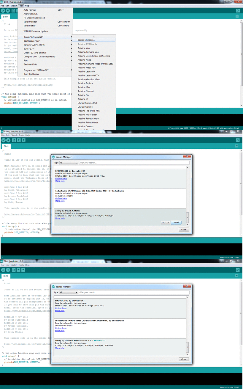
- Now to install the controller Goto "Tools > Board > Board Manager" and install attiny by David A. Mellis
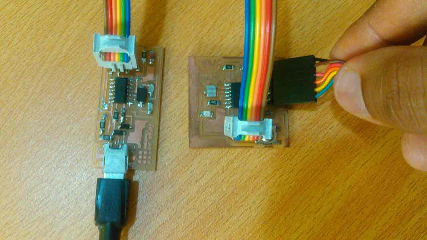
- After installation, connect the board with FabISP and connect FabISP with PC, FTDI Cable is used to power the board.
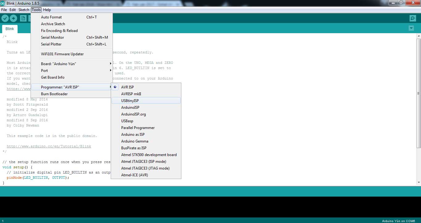
- As we work with FabISP we select Programmer as USBtinyISP.
- These are some settings of controller I programmed in next steps. Board is set as ATtiny24/44/84, processor is ATtiny44 and clock is set as External 20Mhz clock. After entering controller settings click on Burn Bootloader
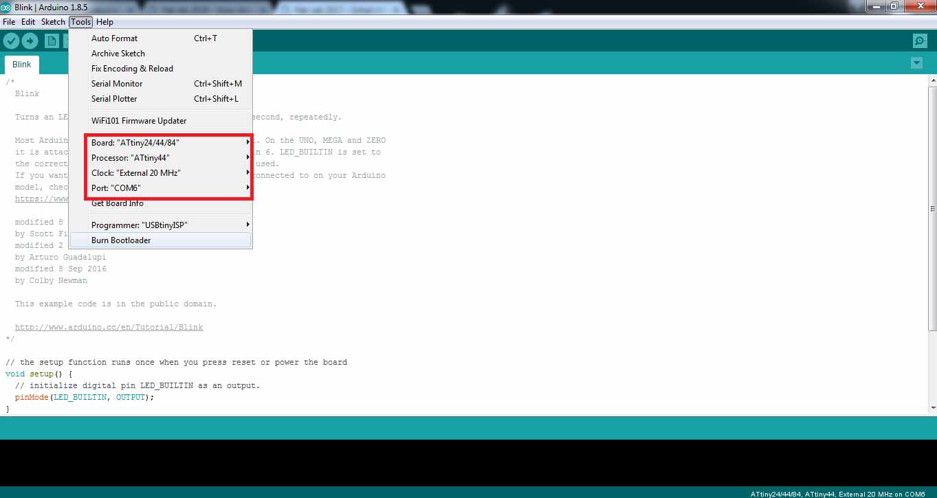
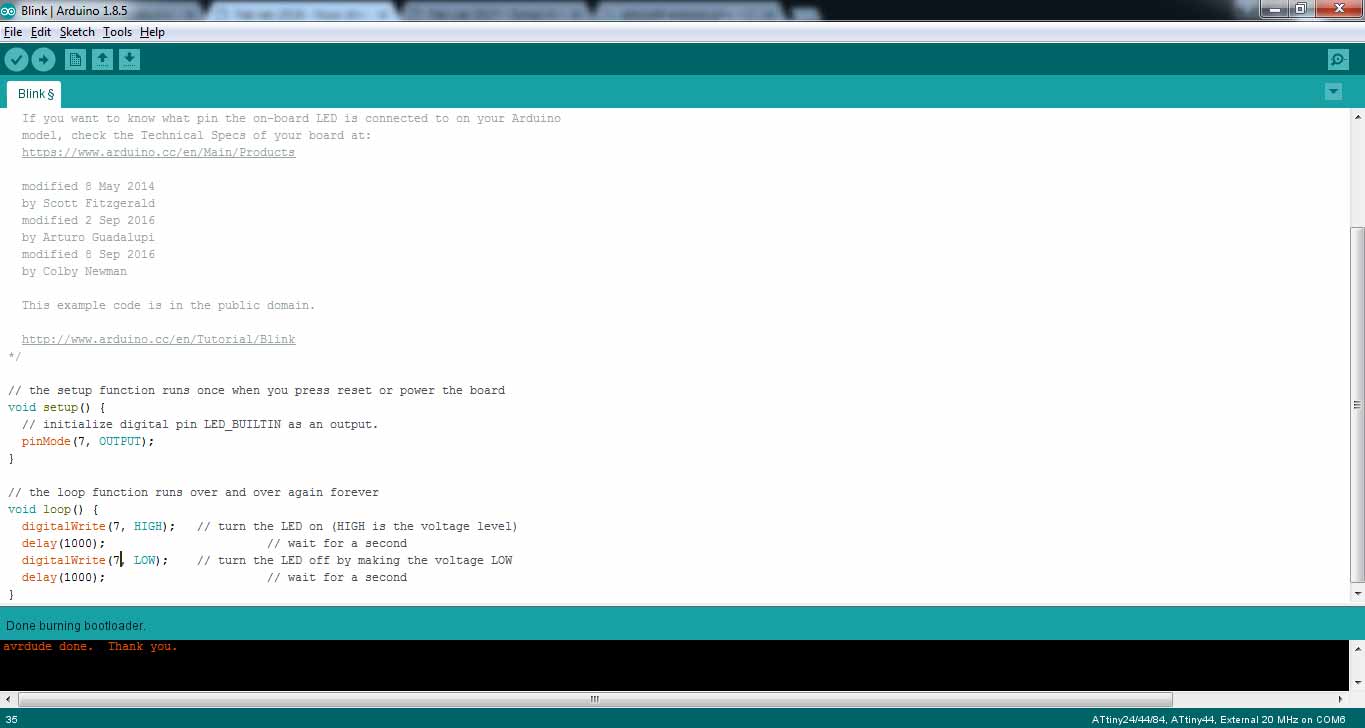
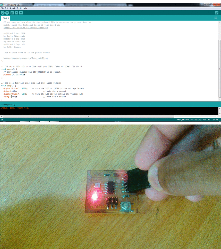
- When a message is received at right bottom corner of code window "Done Burnbootloader" its time to try some sample codes on board. First I try Blink Code by changing LED_BUILTIN to 7 in pinmode as our LED is connected on pin7.
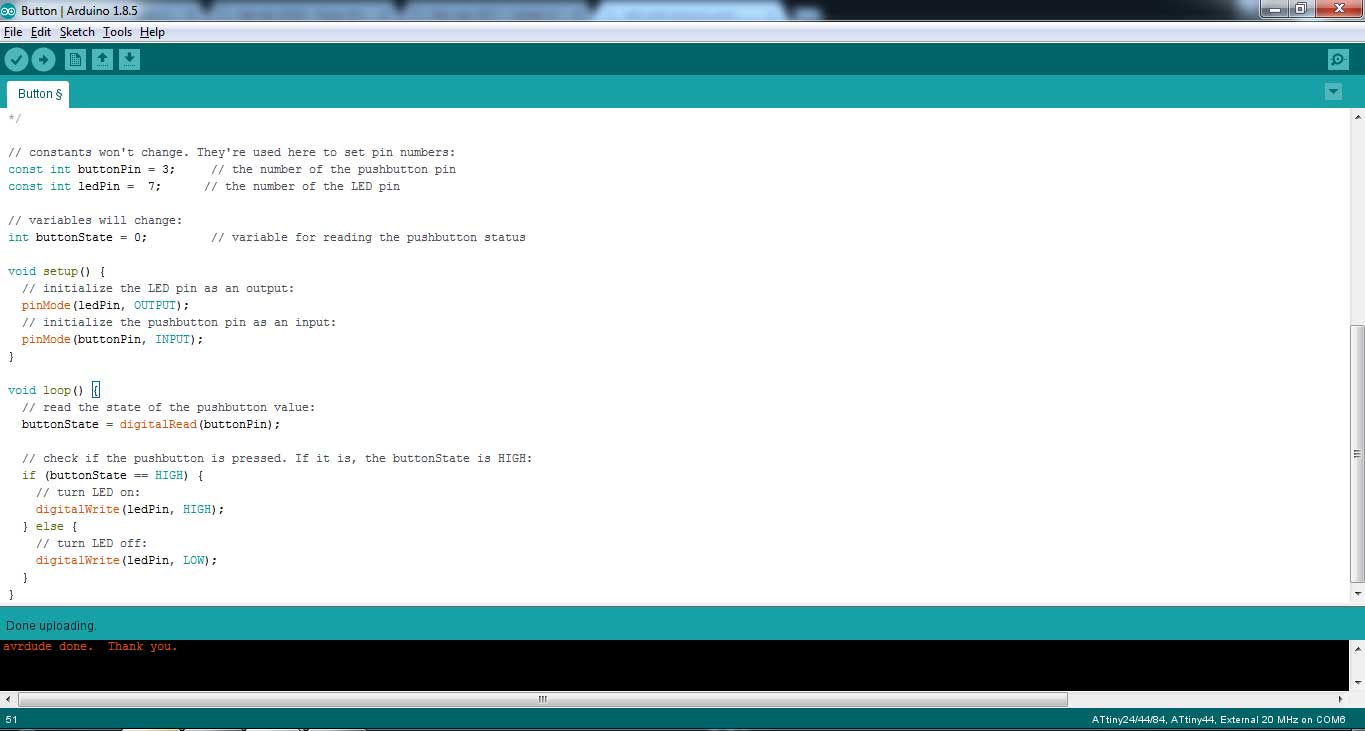
- The board has one output (LED) as well as one input (Button) is present, so I try one more code in which one button is pressed "LED off" and when it released "LED on".
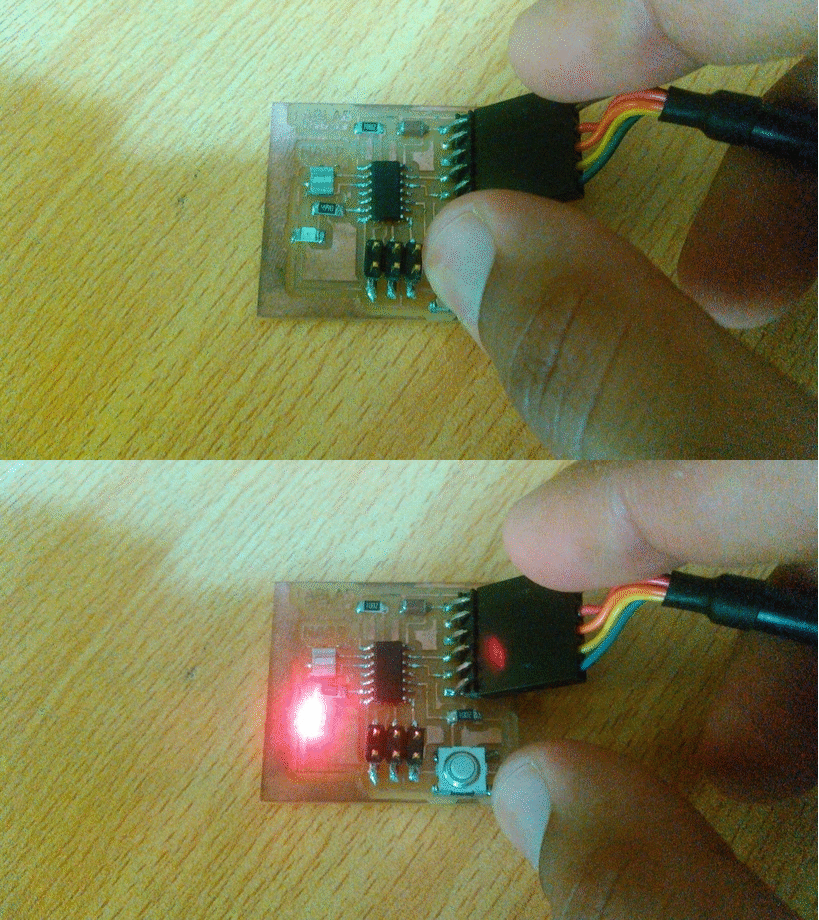
Using Atmel Studio

My second choice to do programming is Atmel Studio. This time I wrote code in C language, here is the procedure:
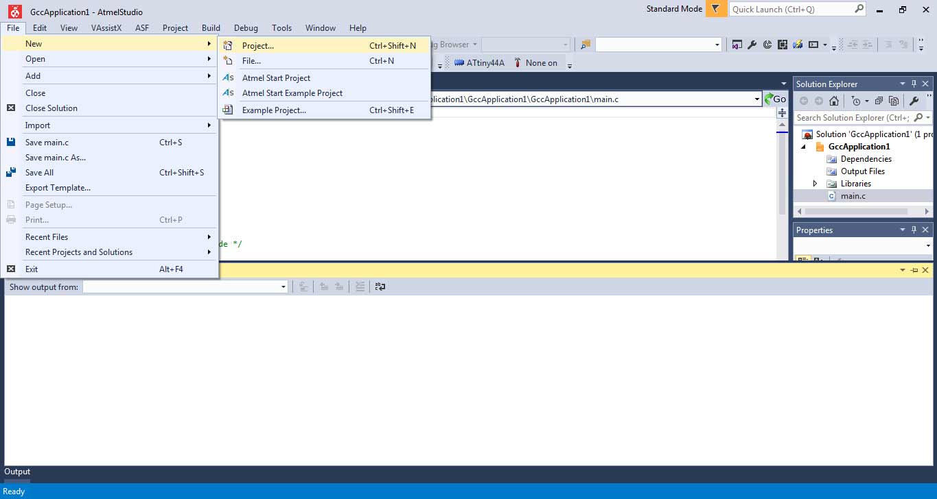
- After opening screen Goto File> New> and click on Project
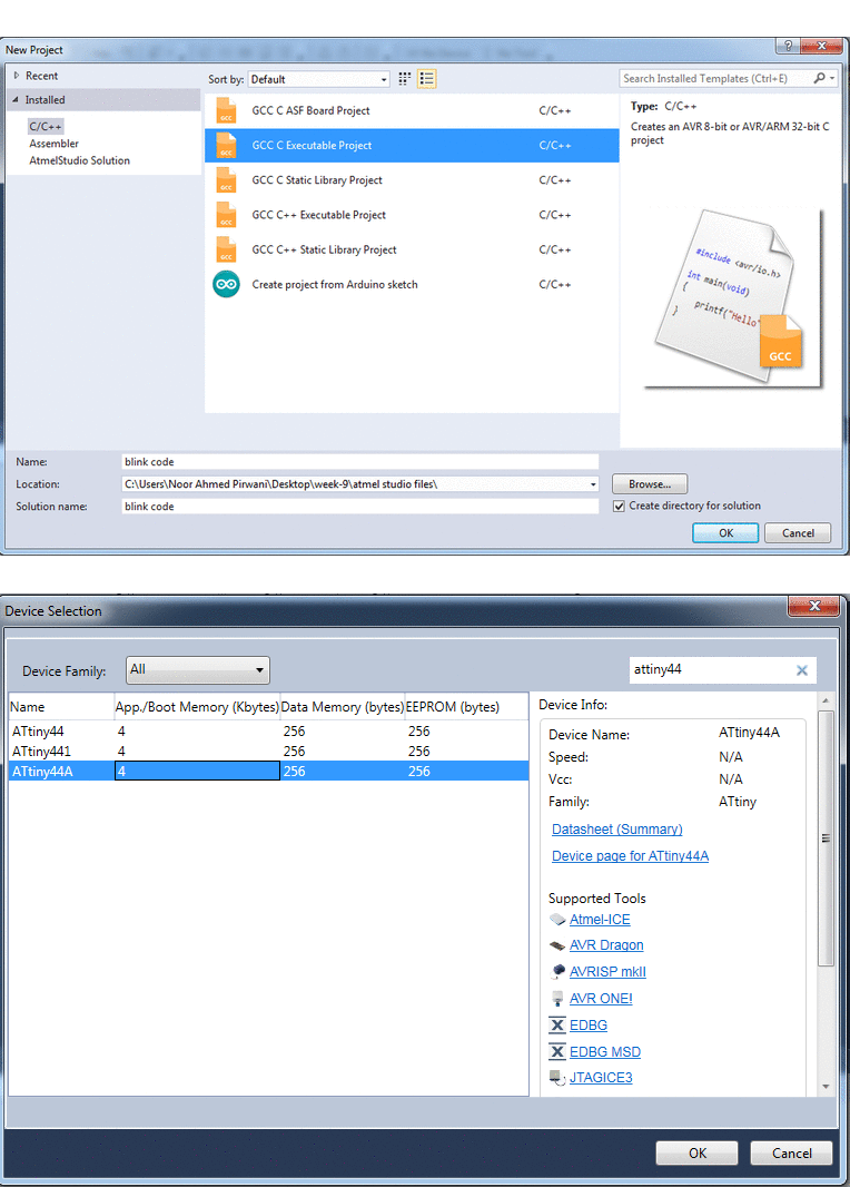
- In new project window select GCC C Executable Project, Name the project and Solution name. It is good practice to create solution it helps software to organize all the files of related project in one folder. After pressing ok in next step select the device in a list in omy case I select "ATtiny44A"
- A main.c tab is appear after setup new project. Main.c tab is used to write code. After writing code click on Build and select Build Solution or press F7
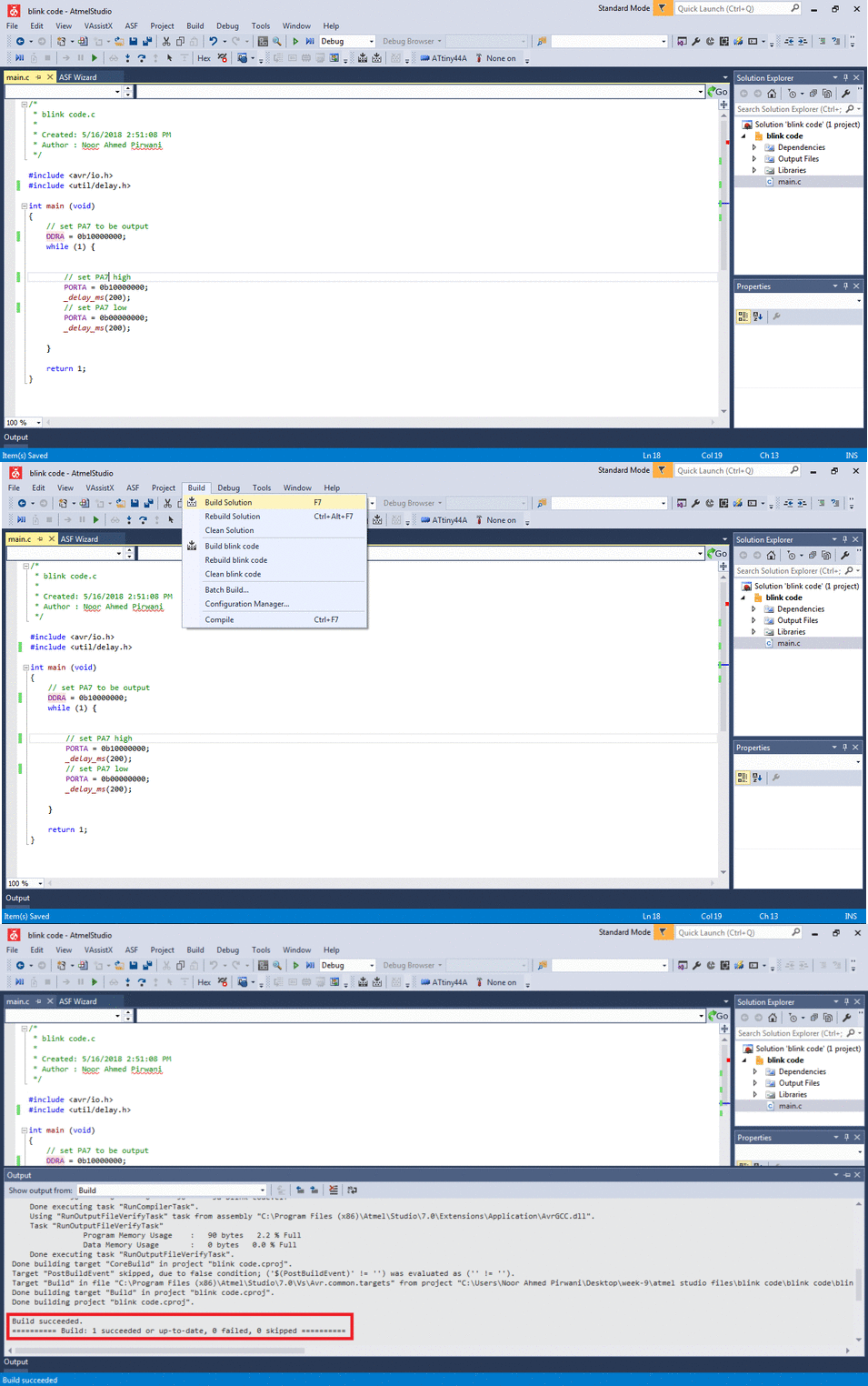
- We need .hex file to upload it on board via avrdude. After building solution the .hex file is available at Solution Explorer tab > Output Files.
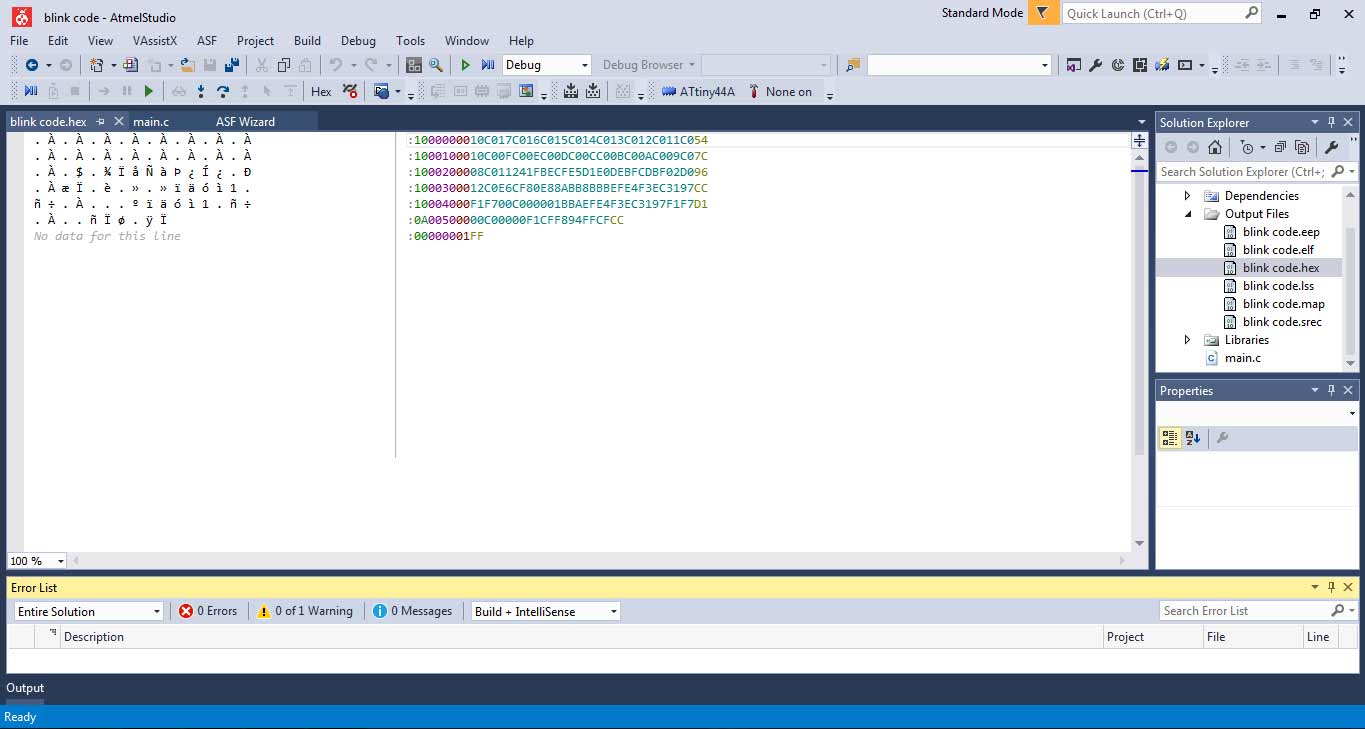
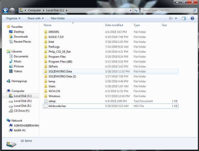
- For simplification in command prompt I trace the .hex file and copy it in C-folder.
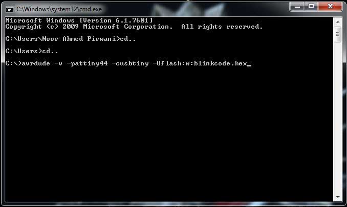
- The command to program using avrdude
"Click here"to download all files of this week

This work is licensed under a Creative Commons Attribution-NonCommercial 4.0 International License
