Week 13 | Output Devices
Fab Academy 2018 | Archive
This week I made an output device which I was using in my Final project. In my final project I was going to use 6 servo motor, so I decided to make a board having servo motor. I referred Neil’s board for making my board using ATTiny 44. Components I used
- LM117 Voltage Regulator
- AVRISP
- ATTiny44
- Capacitor
- Resistor
- 2 - 6 pin headers for servo motor
The task for this week was of making an output device which I would be using in my Final project. I decided to use ATtiny 44 for controlling a servo. Neil already designed one board for servo as a output device, so I refered the same board and redesign it.
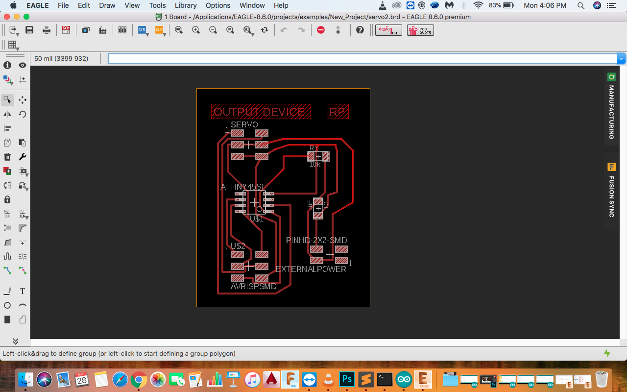
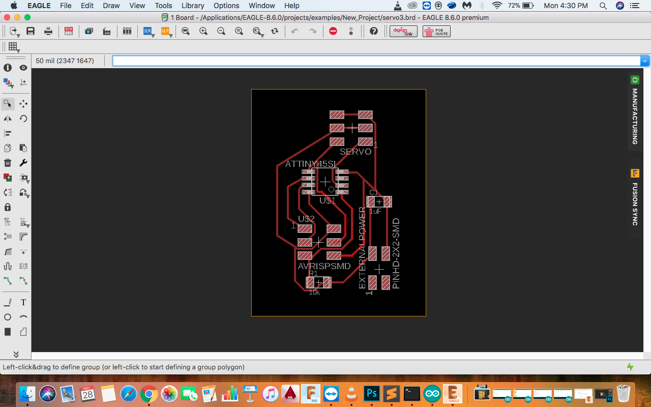
I used Eagle for making the design.
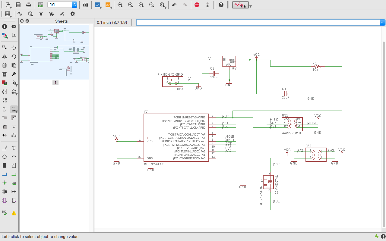
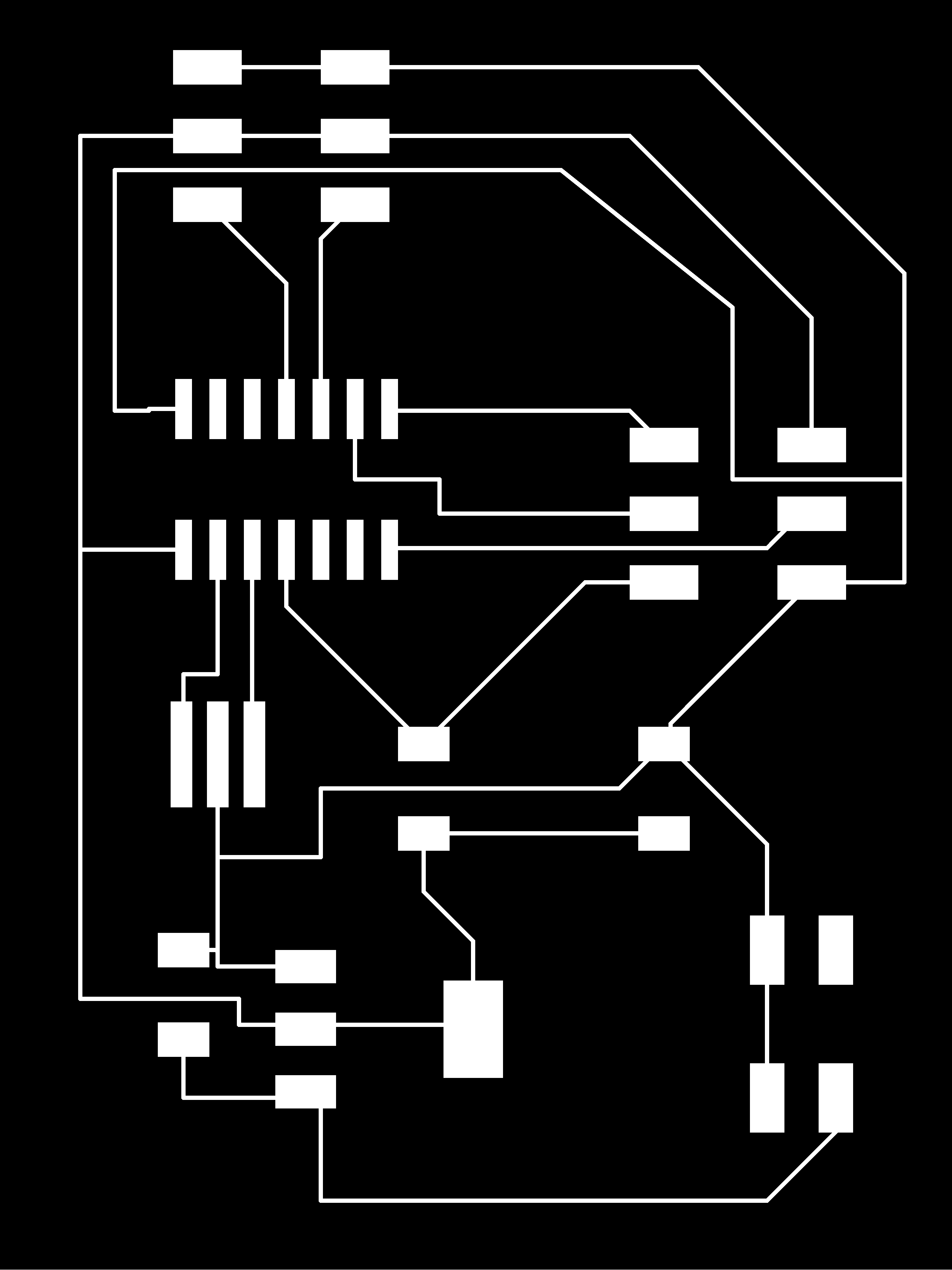
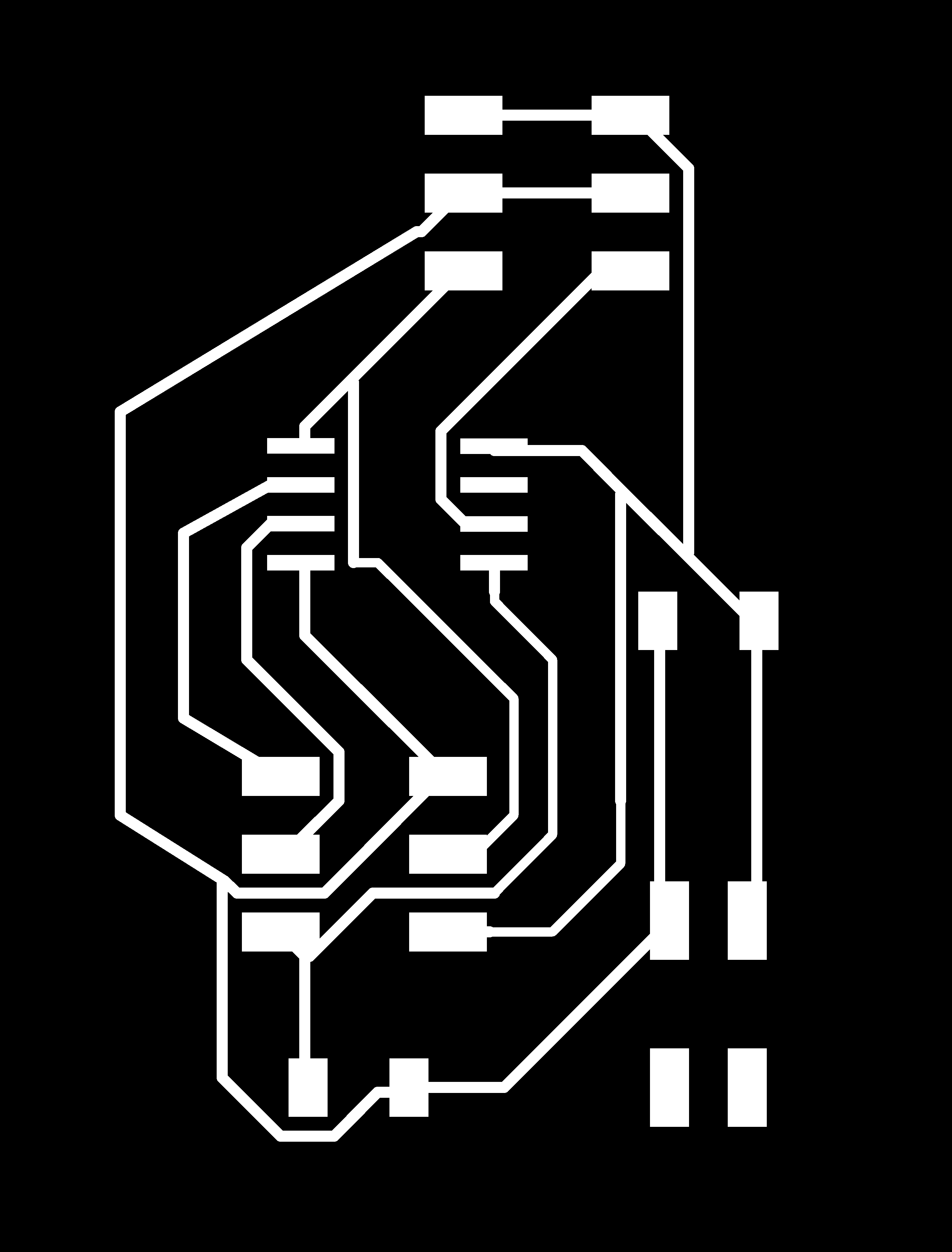
Board of the circuit. I used Autorout for designing the traces and kept it 14 mill. This time I made the boudary a bit bigger so while milling the machine do not cut the traces.
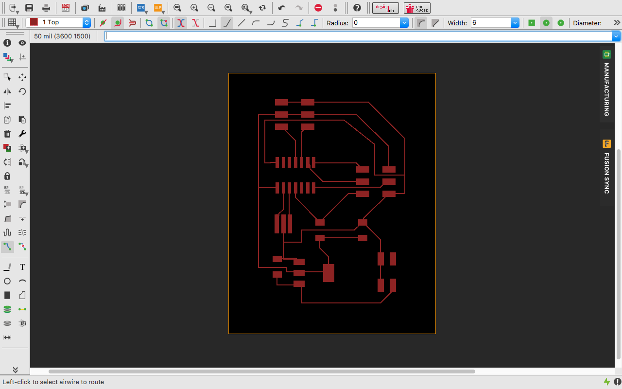
Next step was to open the image in fabmodules to check if any traces are merging or not. I found traces meetong at two places so I had to go back to the Eagle Board and make some schanges. As I had made the traces width as 6 so there is not much merging of the traces.
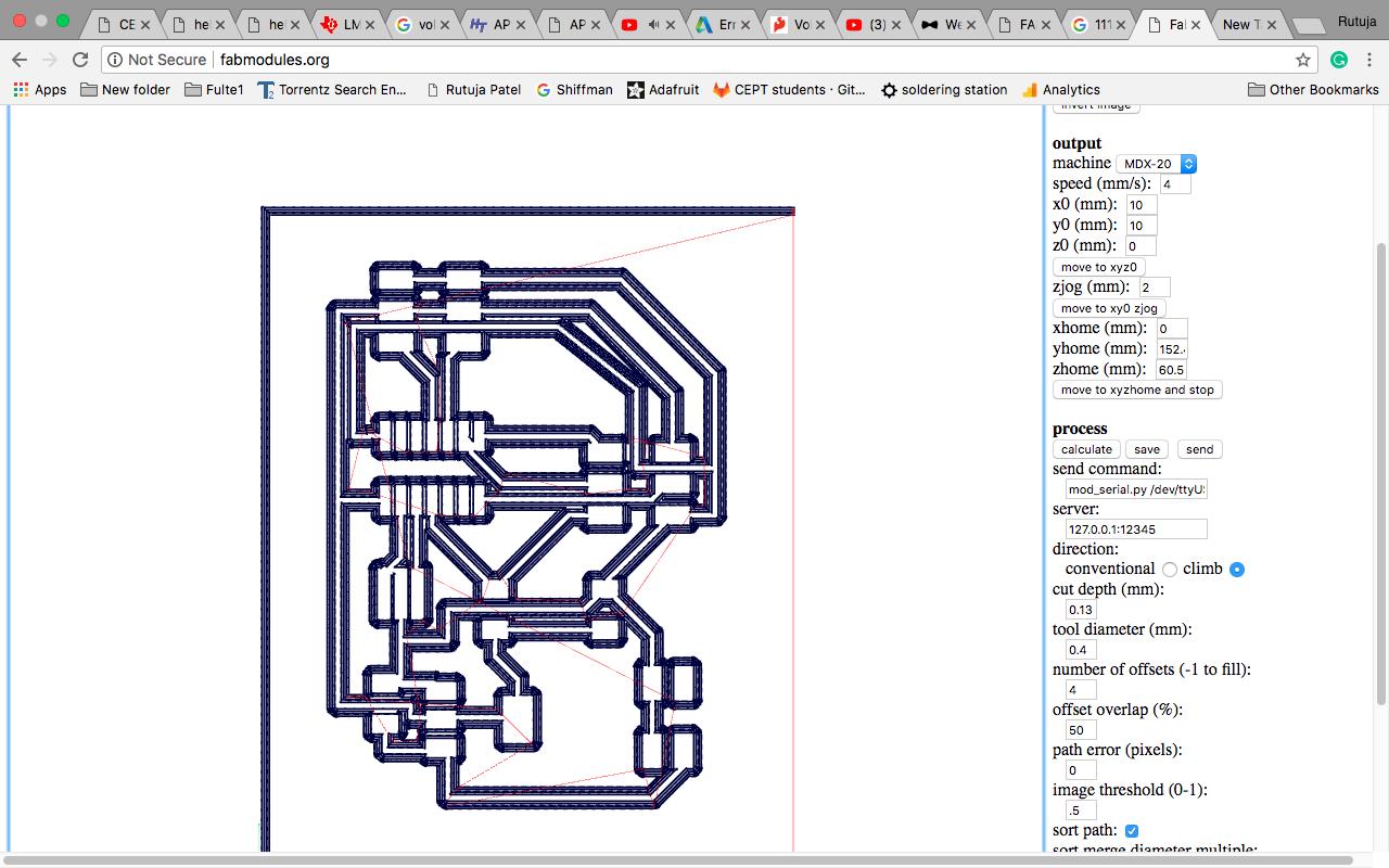
I manually changed the traces and also and then again checked in fabmodules which was showing correct and the traces were also not merging.
Images for Outercut and Traces

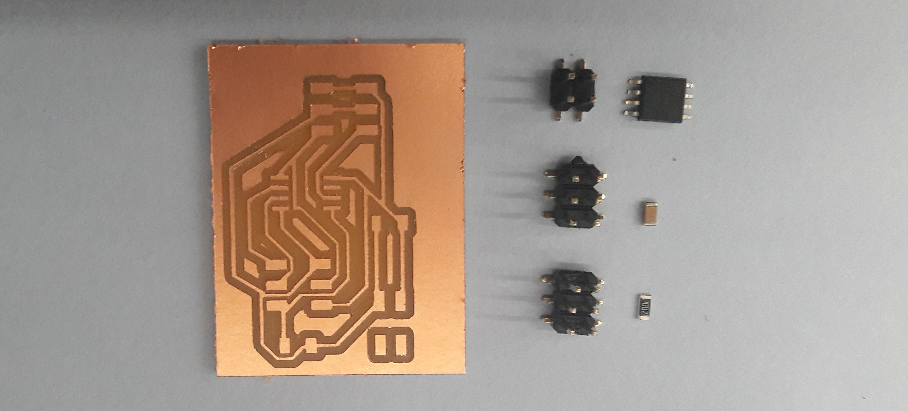
Components I used
- ATtiny 44
- AVRISP
- 10k Resistor
- 22uF Capacitor
- 10uF Capacitor
- 4 Pin Header for Power
- 6 Pin Header for 2 Servo motor
- 20MHz Crystal
- LM 1117 5V Voltage Regulator
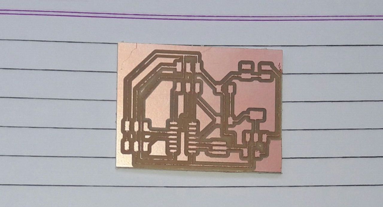
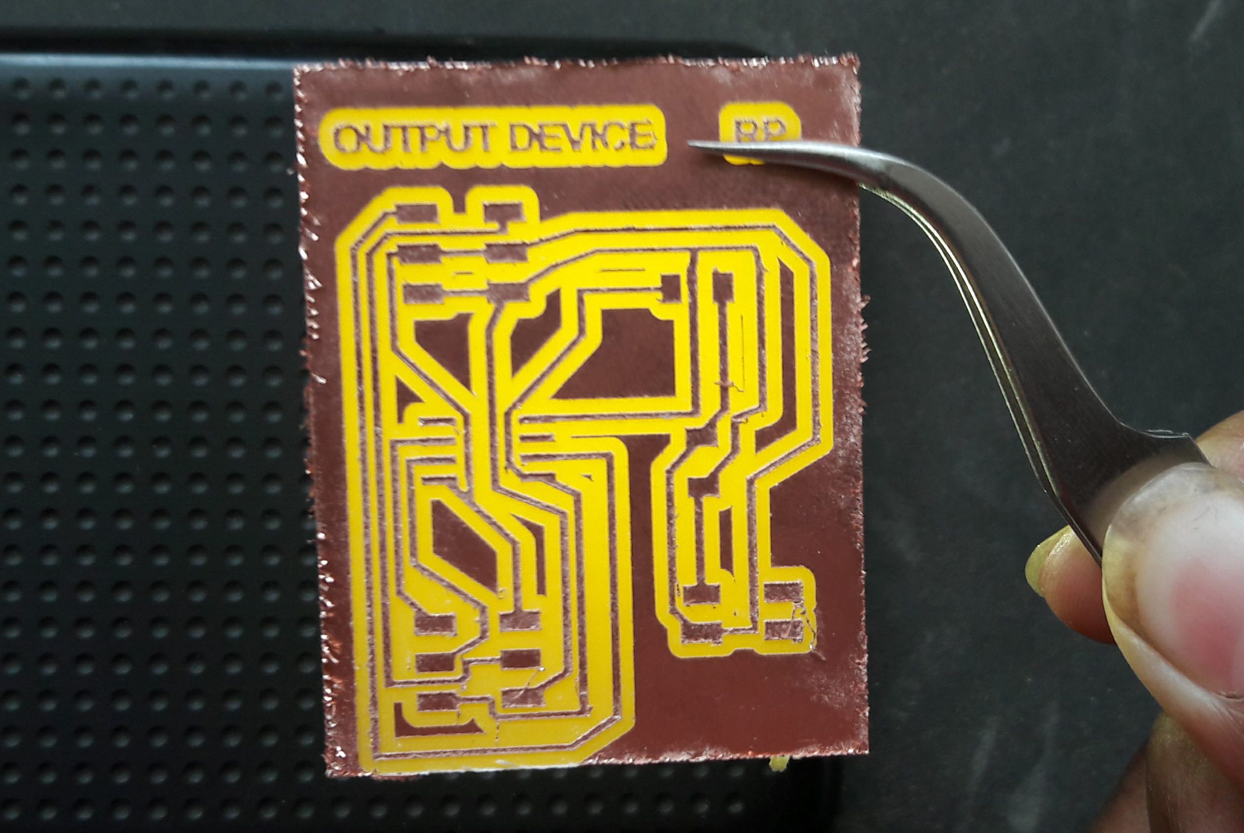
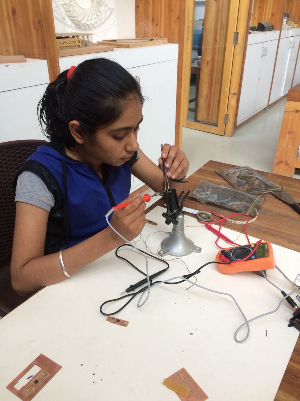
Next step was to mill the board and Solder it. The circuit milled sussessfully at first time.
Now next step was to program the circuit. Unfortunately this time also the circuit didn't work, it programmed but the servo was not working. I also used external power of 12V but still did not work. The servo started but was not moving. It was success till burning bootloader and uploading the program but after that nothing worked. Then I decided to make 328p board.
Milled Board
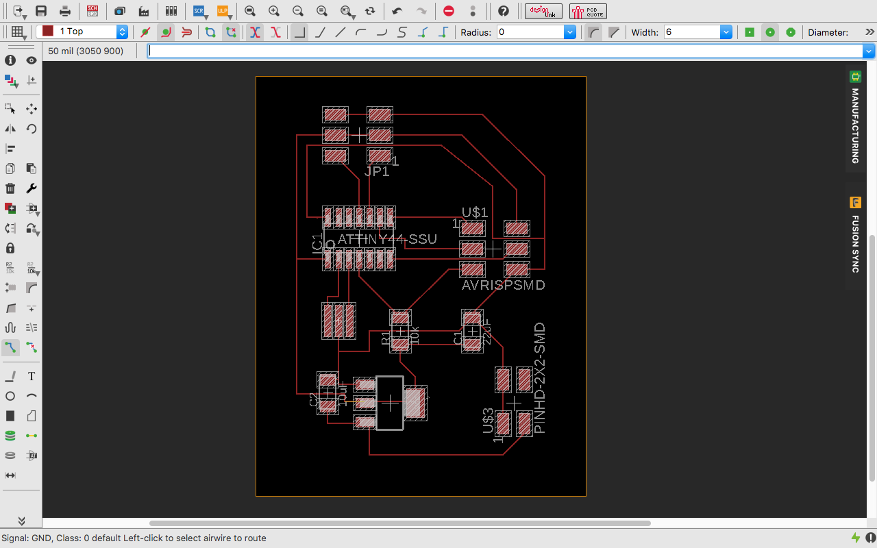
I soldered the board but this time also it didn’t work because I made mistake in in the connection. The MOSI pin of the AVRISP did not get connected to the ATtiny’s MOSI. I made a mistake while making the traces in board view, I didn’t notice the absence of the trace. I fixed the error and made a new board in Eagle.
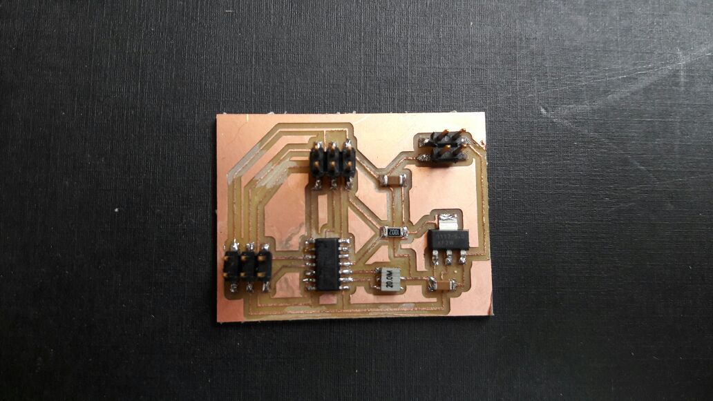
This time I took care in designing the board and successfully I was able to make the board without any mistake. I milled the board and got properly milled.
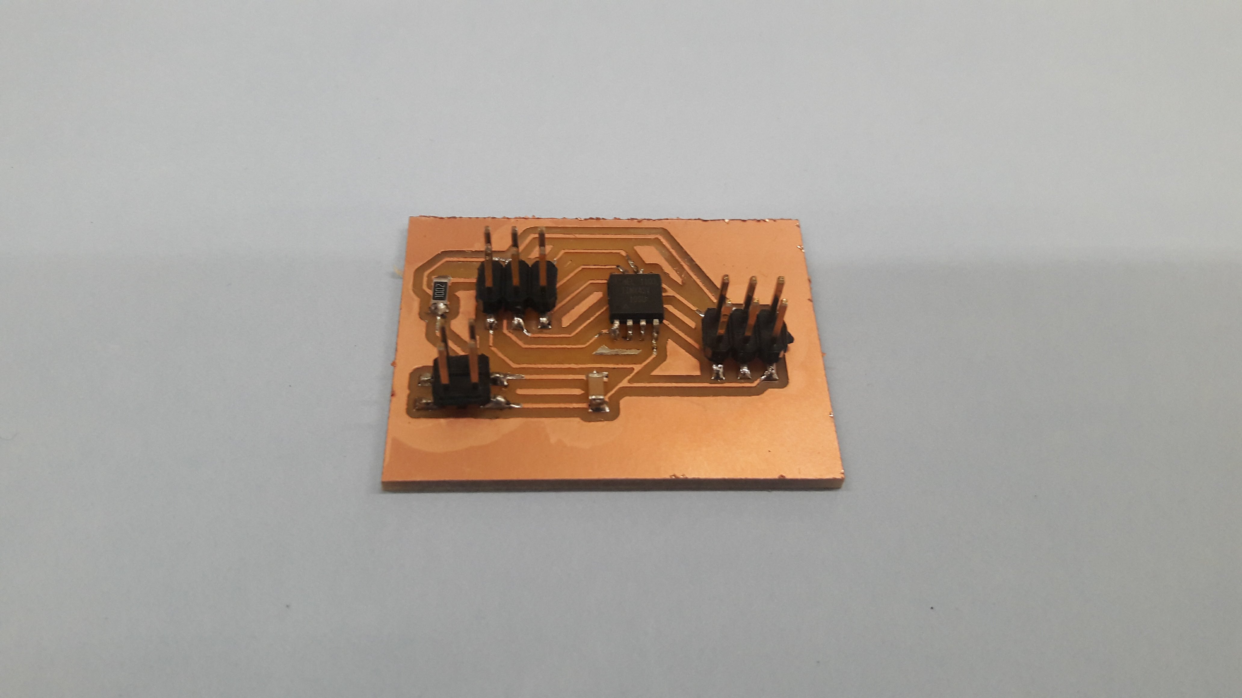
I soldered the board, this time I didn’t find any difficulty in soldering the boars. I checked the board with multimeter, everything was alright.
Next challenge was to program the board. For code, I refered Viraj Gandhi’s website. First, I tested the code for one motor and then attached both the motors.
Code of Ultrasonic with RGB
 #include <SoftwareSerial.h>

#define RX   1
#define TX   0
SoftwareSerial Serial(RX, TX);
void setup()
{
   pinMode(3, OUTPUT);
   pinMode(0, OUTPUT);
}

void loop()
{
   for (int i = 0; i < 45; ++i) {
      digitalWrite(3, HIGH);
      delayMicroseconds(1000);
      digitalWrite(3, LOW);
      delayMicroseconds(1000);
       digitalWrite(0, HIGH);
      delayMicroseconds(2000);
      digitalWrite(0, LOW);
      delayMicroseconds(1800);
    }
     delay(2000);
         for (int i = 0; i < 45; ++i) {
      digitalWrite(3, HIGH);
      delayMicroseconds(1500);
      digitalWrite(3, LOW);
            delayMicroseconds(1800);
        digitalWrite(0, HIGH);
      delayMicroseconds(1500);
      digitalWrite(0, LOW);
      delayMicroseconds(1800);
}
}
Working of One Servo
Working of two servo
Code Explanation
When we write any code, we need to declare everything at the begining.- Servo Library does not work with ATtiny 45 so for using servo with the IC we need to include Software Serial.
- Then define RX and TX pins of the IC.
- In this case the IC's MISO pin is RX (1) and MOSI pin is TX (0)
- I connected servo to pin 3 and 0 of the IC so we need to declare it with the pinout
 #include <SoftwareSerial.h>

#define RX   1
#define TX   0
SoftwareSerial Serial(RX, TX);
void setup()
{
   pinMode(3, OUTPUT);
   pinMode(0, OUTPUT);
}
For continuous rotation of the servo motor, we need to apply loop in the code
- We use digitalWrite to write HIGH or LOW to the pin. High means the servo will move upto 45 degree angle and Low means it will come back again to the zero position
- For giving Delay we use delayMicroseconds command
void loop()
{
   for (int i = 0; i < 45; ++i) {
      digitalWrite(3, HIGH);
      delayMicroseconds(1000);
      digitalWrite(3, LOW);
      delayMicroseconds(1000);
       digitalWrite(0, HIGH);
      delayMicroseconds(2000);
      digitalWrite(0, LOW);
      delayMicroseconds(1800);
    }
     delay(2000);
         for (int i = 0; i < 45; ++i) {
      digitalWrite(3, HIGH);
      delayMicroseconds(1500);
      digitalWrite(3, LOW);
            delayMicroseconds(1800);
        digitalWrite(0, HIGH);
      delayMicroseconds(1500);
      digitalWrite(0, LOW);
      delayMicroseconds(1800);
}
}
Files
Rutuja Patel
EC Engineer
Get in touch
I am EC engineer doing my BE at state university at Gujarat, India.
- rutujapatel1201@gmail.com
- Sen me a Mail
- Iscon, Ahmedabad,
Gujarat, IN 380015