Week 9 | Embedded Programming
Fab Academy 2018 | Archive
Embedded Programming
This week I programmed the board which I made in my electronics design week. I havepractised programming with arduino board but programming Attiny board was new and interesting.
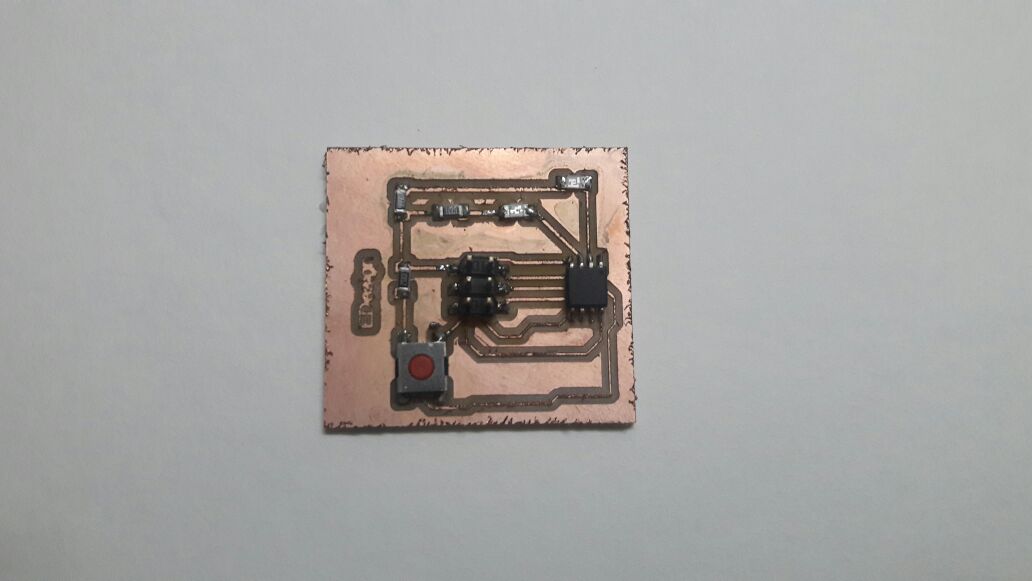
For more information you can visit my week 7 For programming the board with our computer we need to make our board talk with the computer i.e transfer the data from computer to board and vice versa.
First of all we need to understand the ATtiny 45 IC pinout and Datasheet properly.
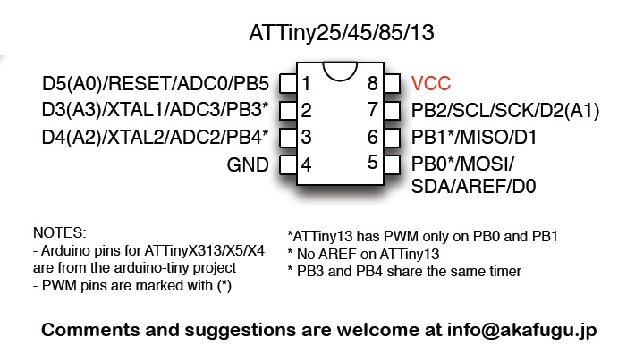
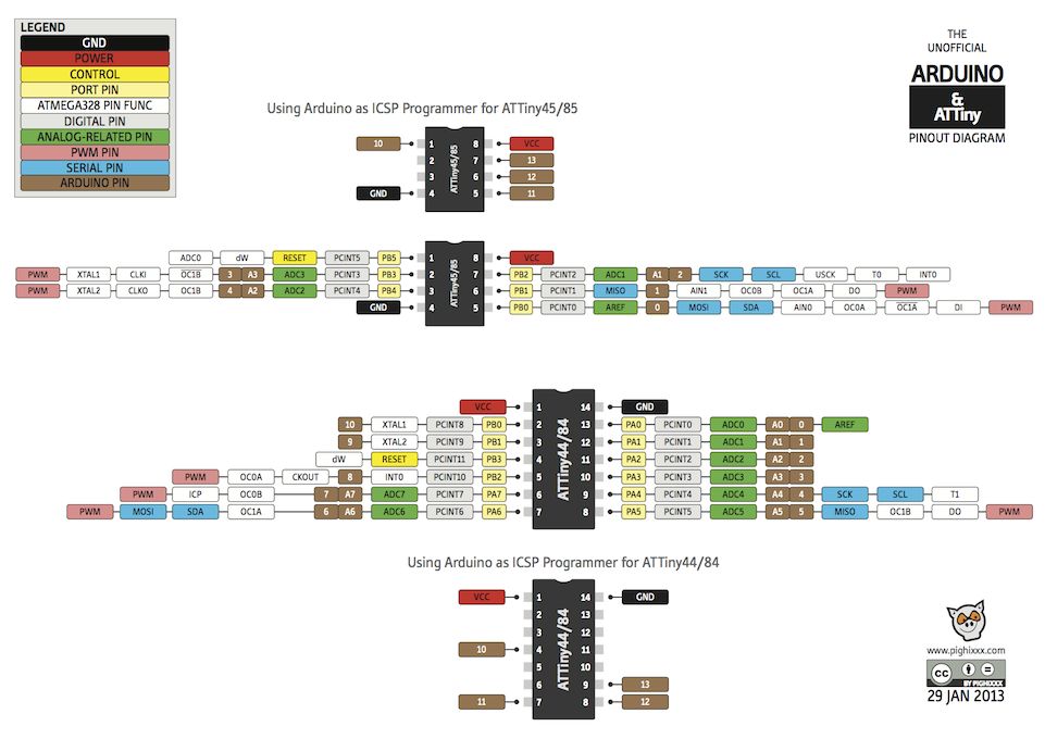
Understanding the pins of AVRISP
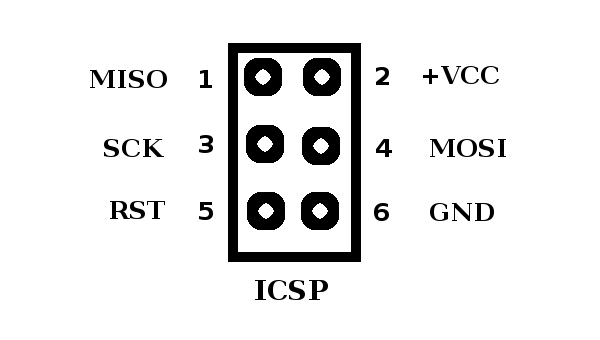
For programming any board we need to include these pins in our board. Some notes to understand the ISP
Arduino is an open source electronic based software on easy to use hardware and software. First we need to download and install the arduino software. For using ATtiny 45 we need to install the ATtiny board from the Preferences tab in the Arduino Software.
Add the URL in “Additional Boards Manager URL”.
https://raw.githubusercontent.com/damellis/attiny/ide-1.6.x-boards-manager/package_damellis_attiny_index.json
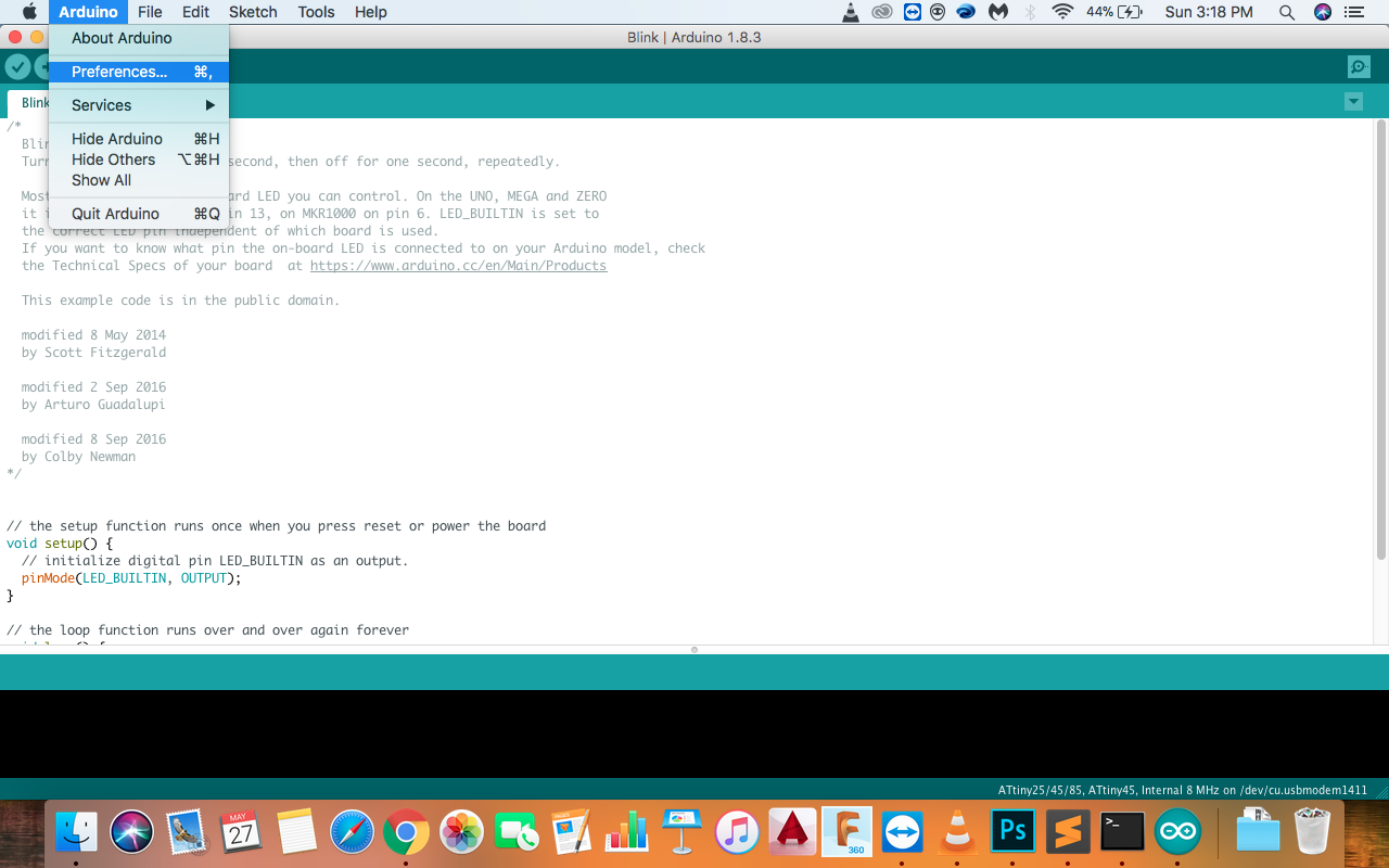
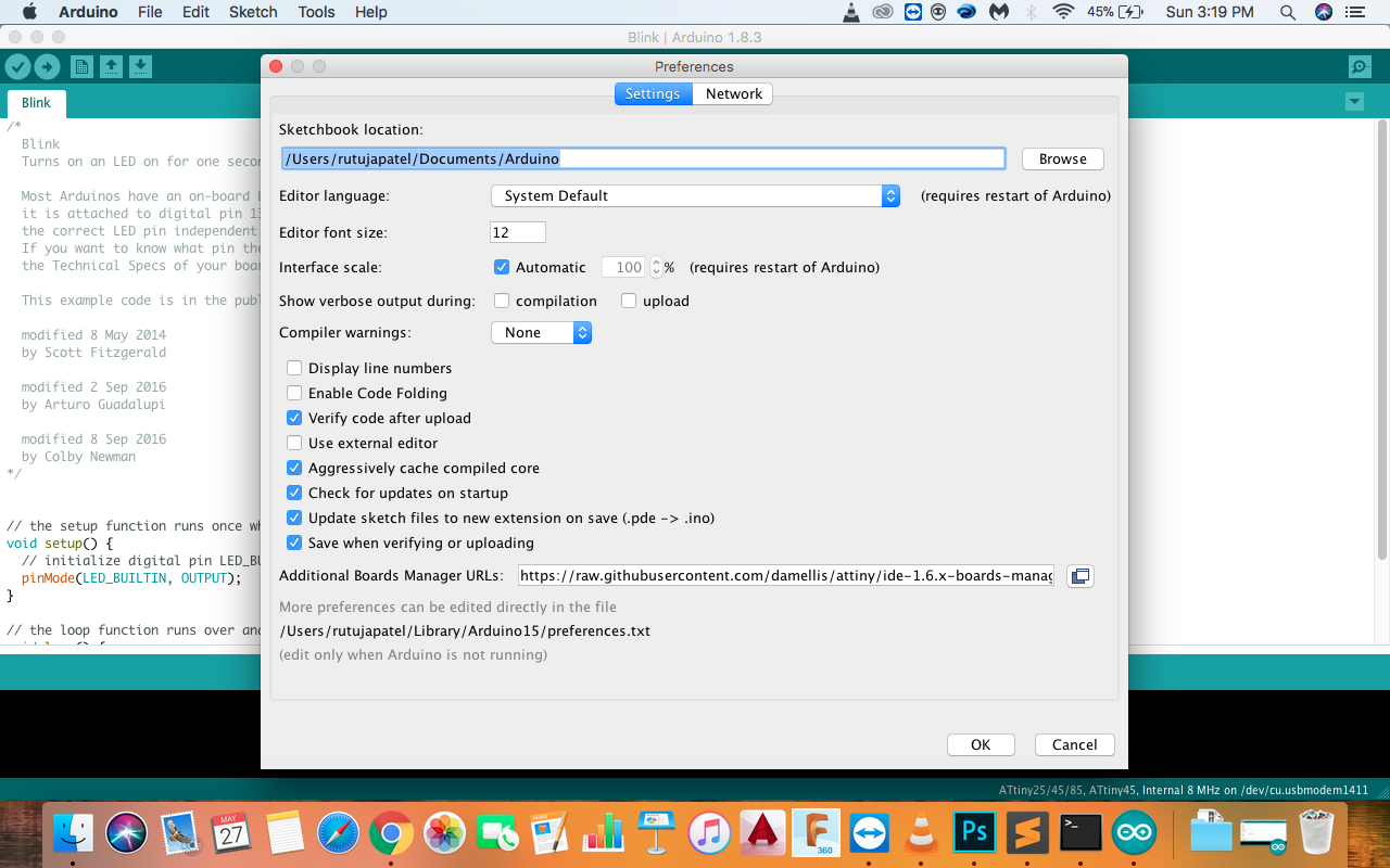
Now go to Tools << Board << Board Manager and install the ATtiny board.
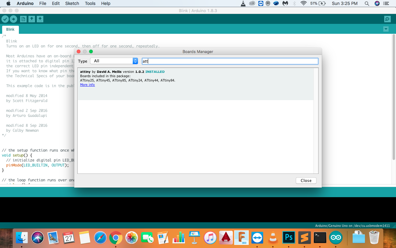
Now you can see the ATtiny board
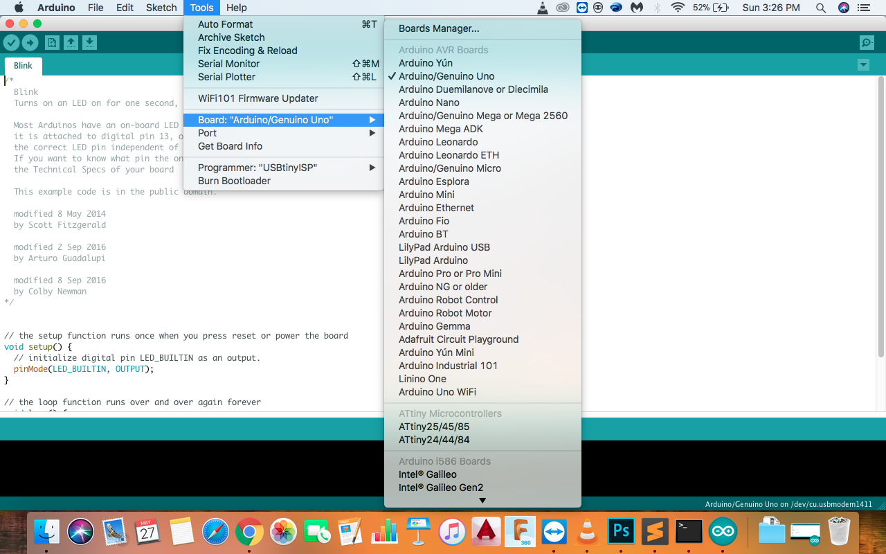
Now for programming, I used the hello echo board which I made in the electronics production week. I connected the AVRISP headers of both the boards for programming and added the code to the software.
Image of connection of the ISP headers
In this I have used basic Coding which is of controlling two LED's with the button in the circuit.

For more information you can visit my week 7 For programming the board with our computer we need to make our board talk with the computer i.e transfer the data from computer to board and vice versa.
First of all we need to understand the ATtiny 45 IC pinout and Datasheet properly.


Understanding the pins of AVRISP

For programming any board we need to include these pins in our board. Some notes to understand the ISP
- MOSI : Master out Slave in - This pin is used to transfer data from computer to the microprocessor
- MISO : Master in Slave out - This pin is used to read data from the microprocessor
- RST : reset pin - This pin is used to reset the microprocessor
- SCK : clock - Clock signal is supplied with help of this pin
- VCC : Voltage supply
- GND : Ground
Arduino is an open source electronic based software on easy to use hardware and software. First we need to download and install the arduino software. For using ATtiny 45 we need to install the ATtiny board from the Preferences tab in the Arduino Software.
Add the URL in “Additional Boards Manager URL”.
https://raw.githubusercontent.com/damellis/attiny/ide-1.6.x-boards-manager/package_damellis_attiny_index.json


Now go to Tools << Board << Board Manager and install the ATtiny board.

Now you can see the ATtiny board

Now for programming, I used the hello echo board which I made in the electronics production week. I connected the AVRISP headers of both the boards for programming and added the code to the software.
Image of connection of the ISP headers
Code of LED Blink using DELAY
      const int buttonPin = 2;      // the number of the pushbutton pin
      const int GreenLed =  3;
      const int RedLed =  4;        // the number of the LED pin
// variables will change:

      int buttonState = 0;         // variable for reading the pushbutton status

      void setup() {

// initialize the LED pin as an output:
        pinMode(GreenLed, OUTPUT);
        pinMode(ledPin, OUTPUT);
// initialize the pushbutton pin as an input:
        pinMode(buttonPin2, INPUT);
}


      void loop() {
// read the state of the pushbutton value:
        buttonState = digitalRead(buttonPin);
// check if the pushbutton is pressed. If it is, the buttonState is HIGH:
        if (buttonState == HIGH) {
// turn LED on:
        digitalWrite(GreenLed, HIGH);
      } else {
// turn LED off:
        digitalWrite(RedLed, LOW);
  }
}
Video of LED Blink using Code
In this I have used basic Coding which is of controlling two LED's with the button in the circuit.
