Week 12 | Input Devices
Fab Academy 2018 | Archive
Ultrasonic as Intput by Trig & Echo Data it changes RGB LED according to prefered distance in code
This week was for making an input device which I was going to use in my final project. I was going to use Ultrasonic sensor as an input device. This week I wanted to use the ATtiny 44 board so I designed a board with ultrasonic sensor and added RGB led into the board.
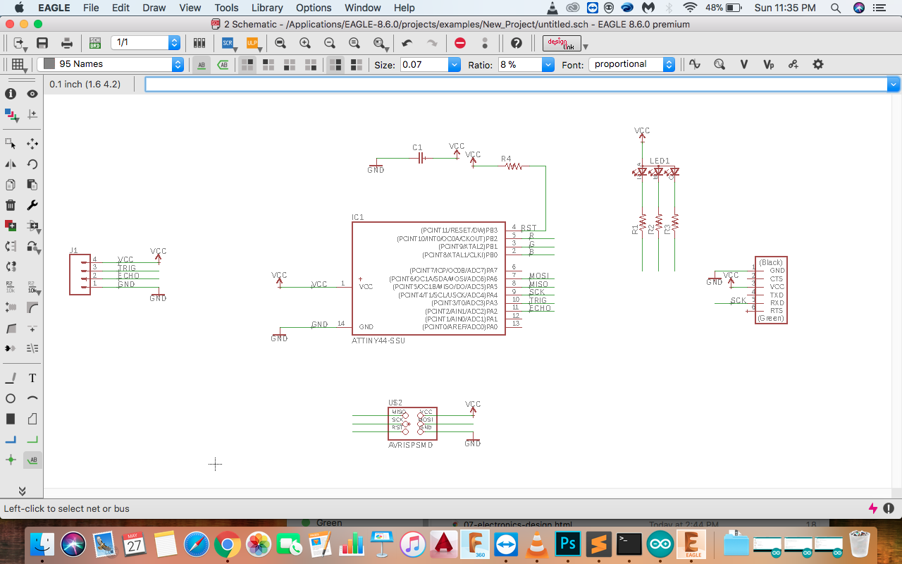
I used Eagle to design the PCB using the ATTiny 44.
The components I used:
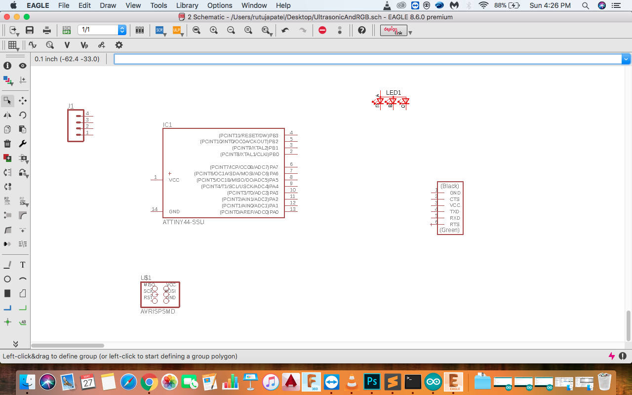
Connecting the components at the required pin number.
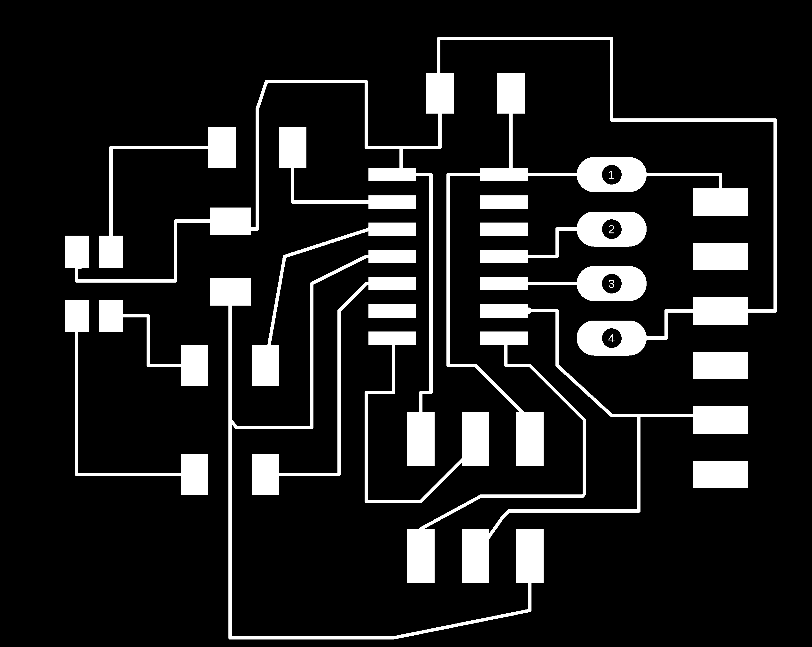
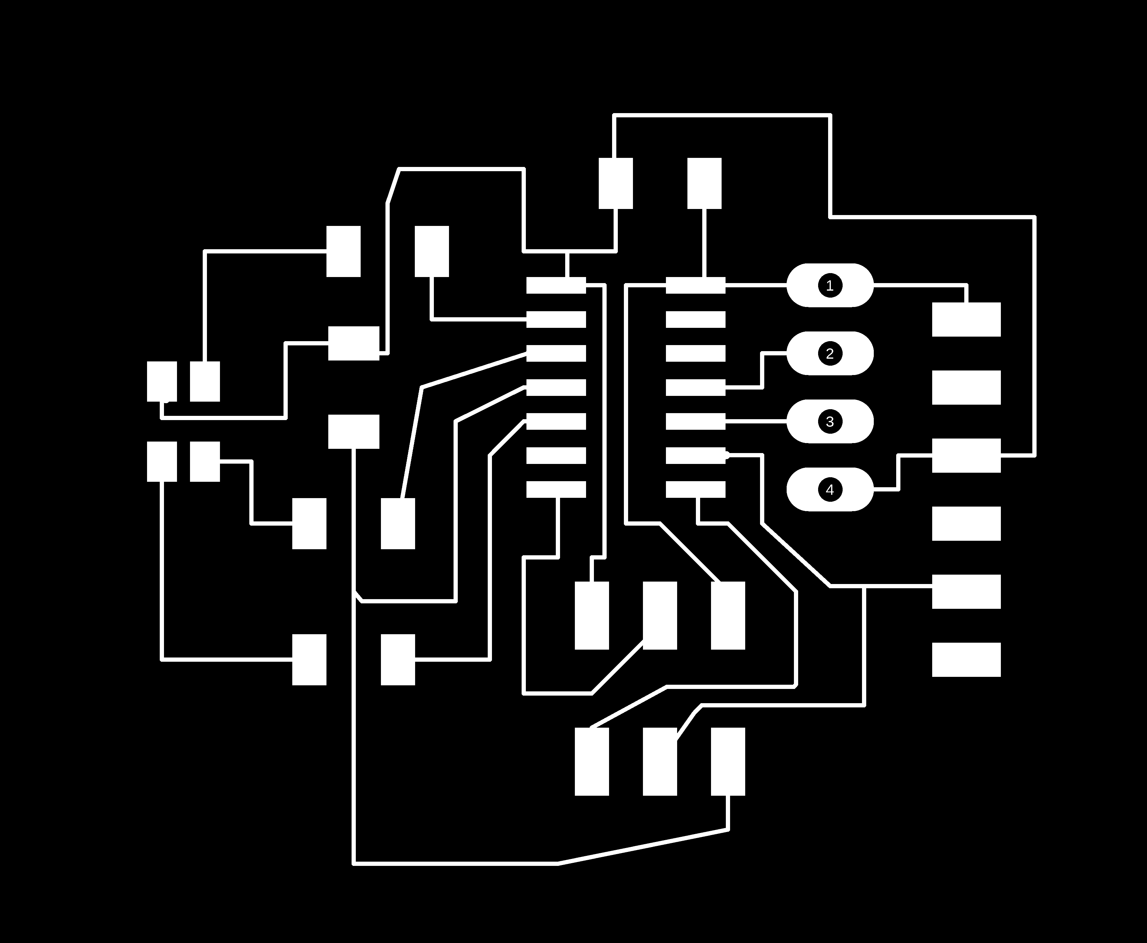
Eagle board view
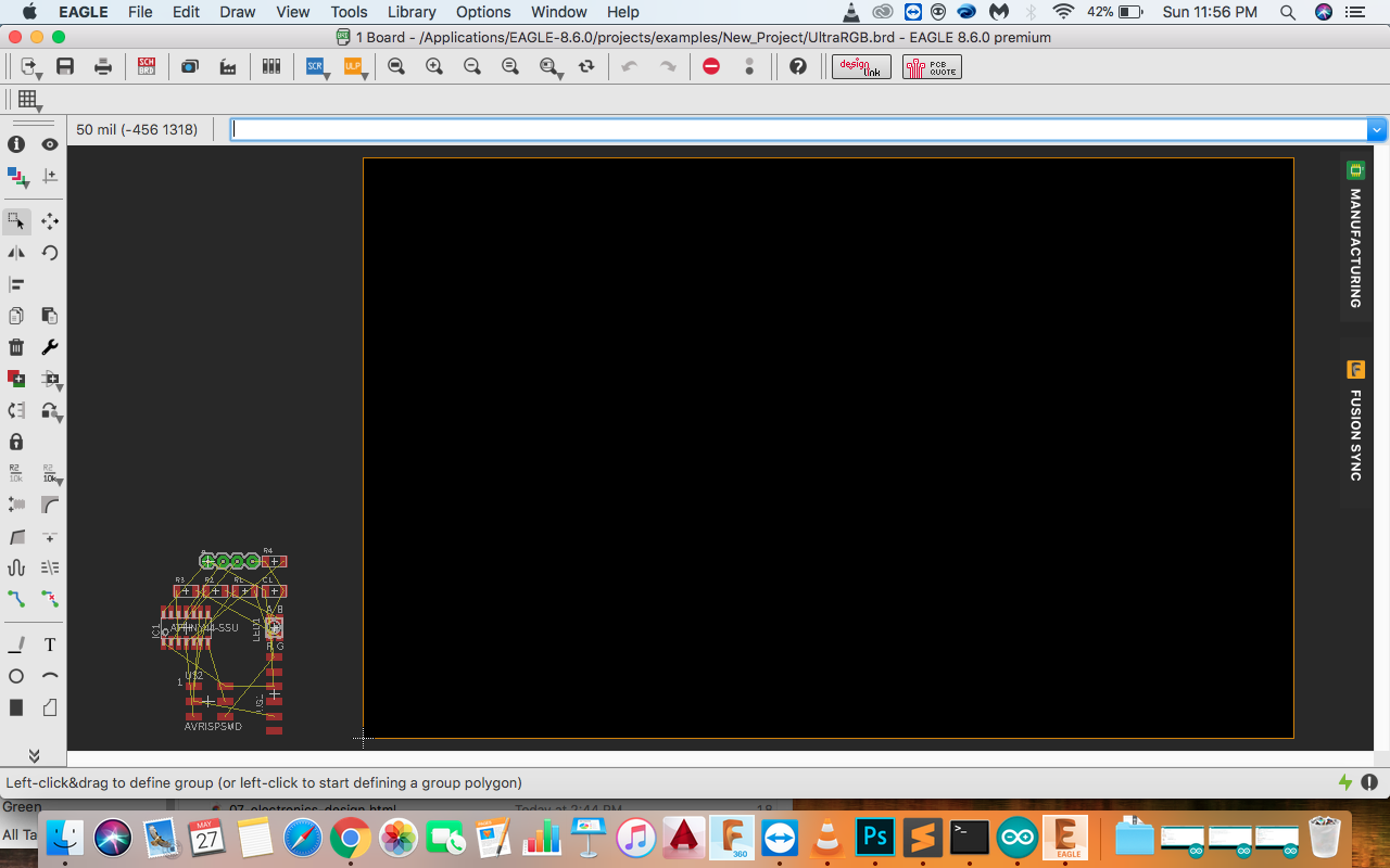
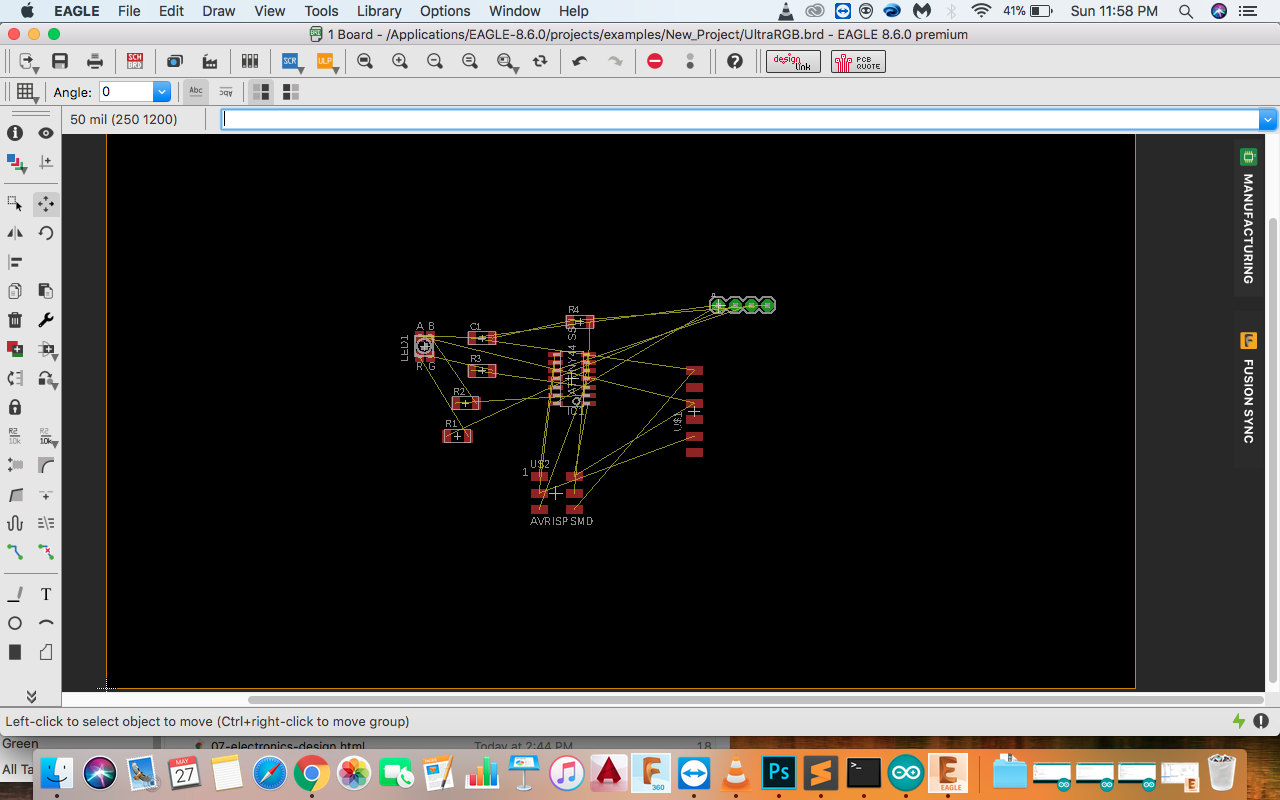
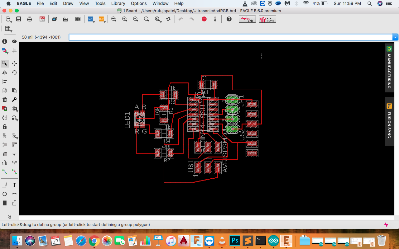
I used Auto-rout command to generate the traces and made some changes in the path for making it look more better.
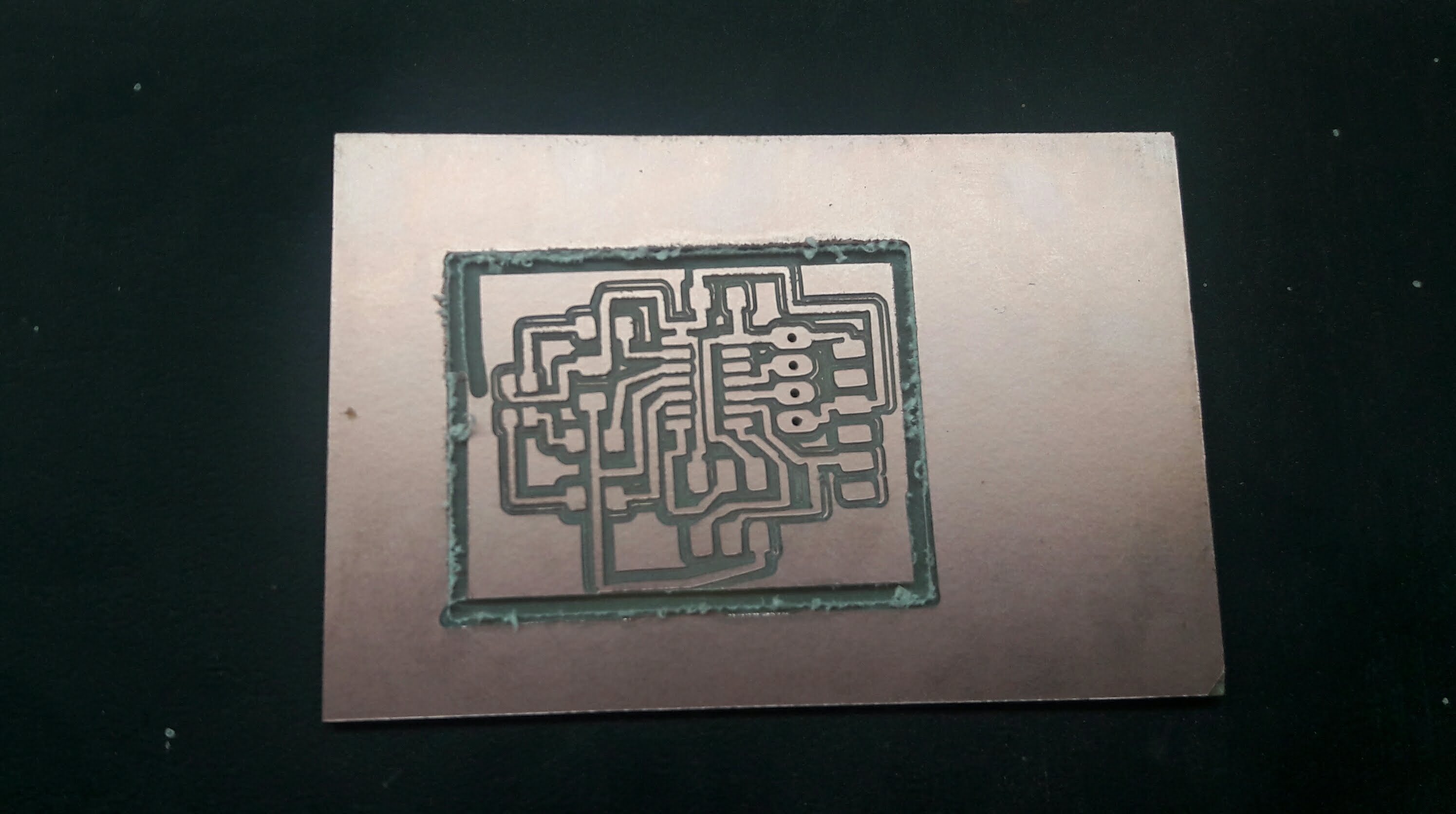
This happens when the board does not stick properly to the machine’s bed, the board starts moving and all the traces gets merged As the board got wasted, I milled another board with sticking a good quality tape and it milled properly. Now the board was ready to be soldered.
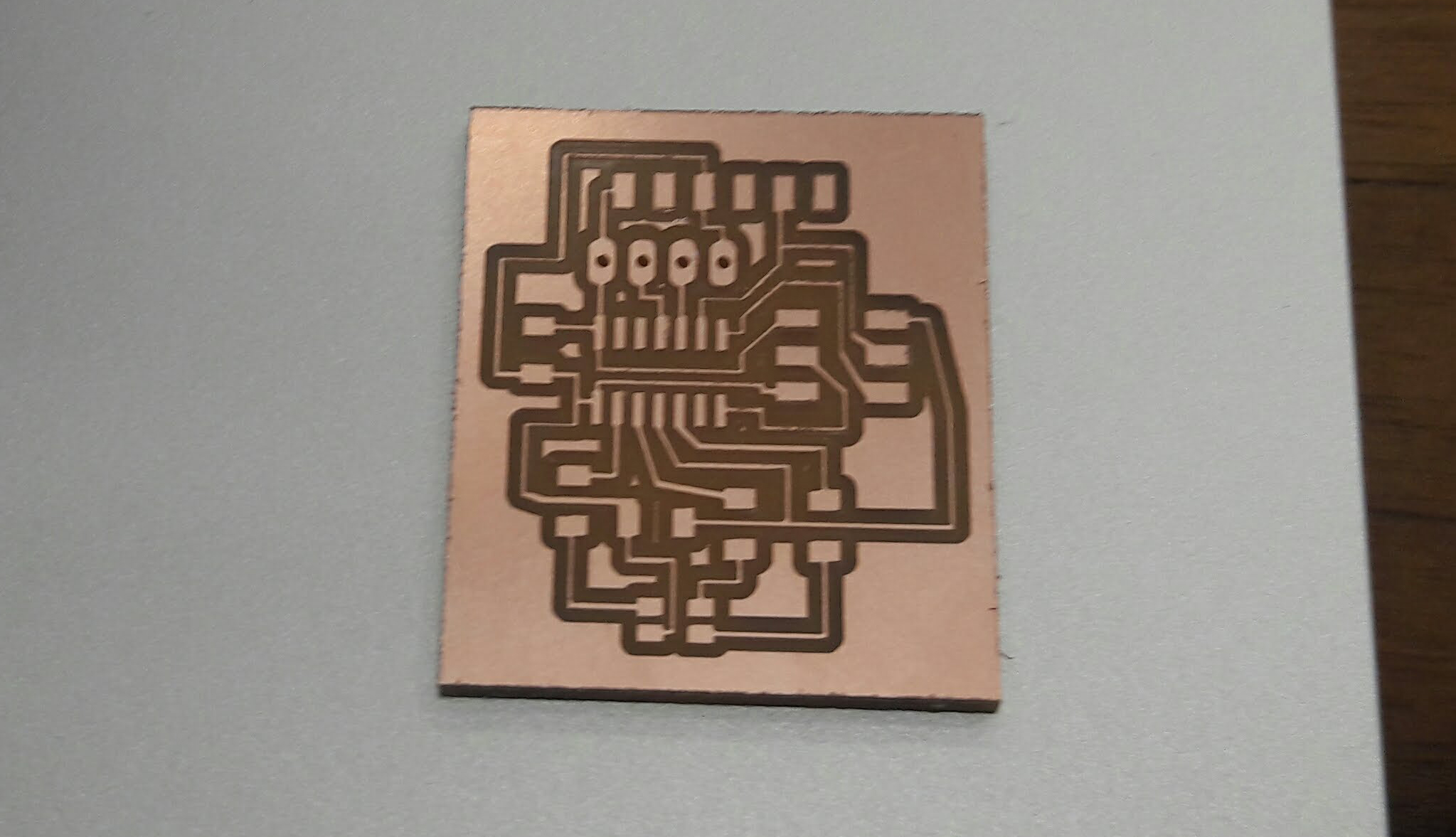
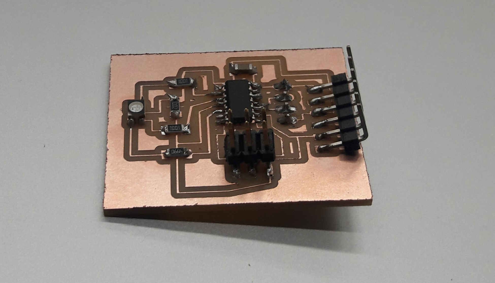
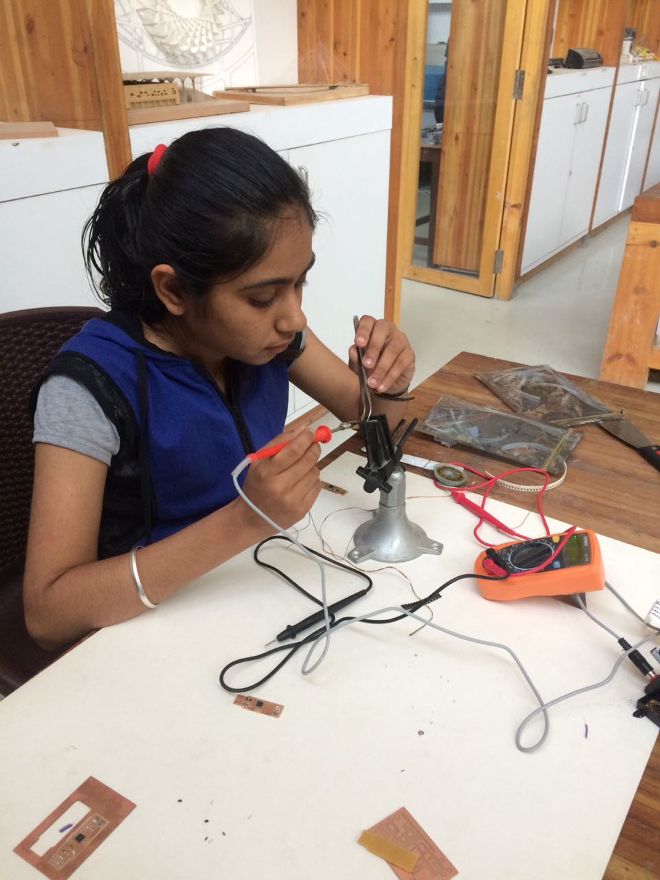
I tested the board with multimeter, all the connections were perfect and no part was merging.
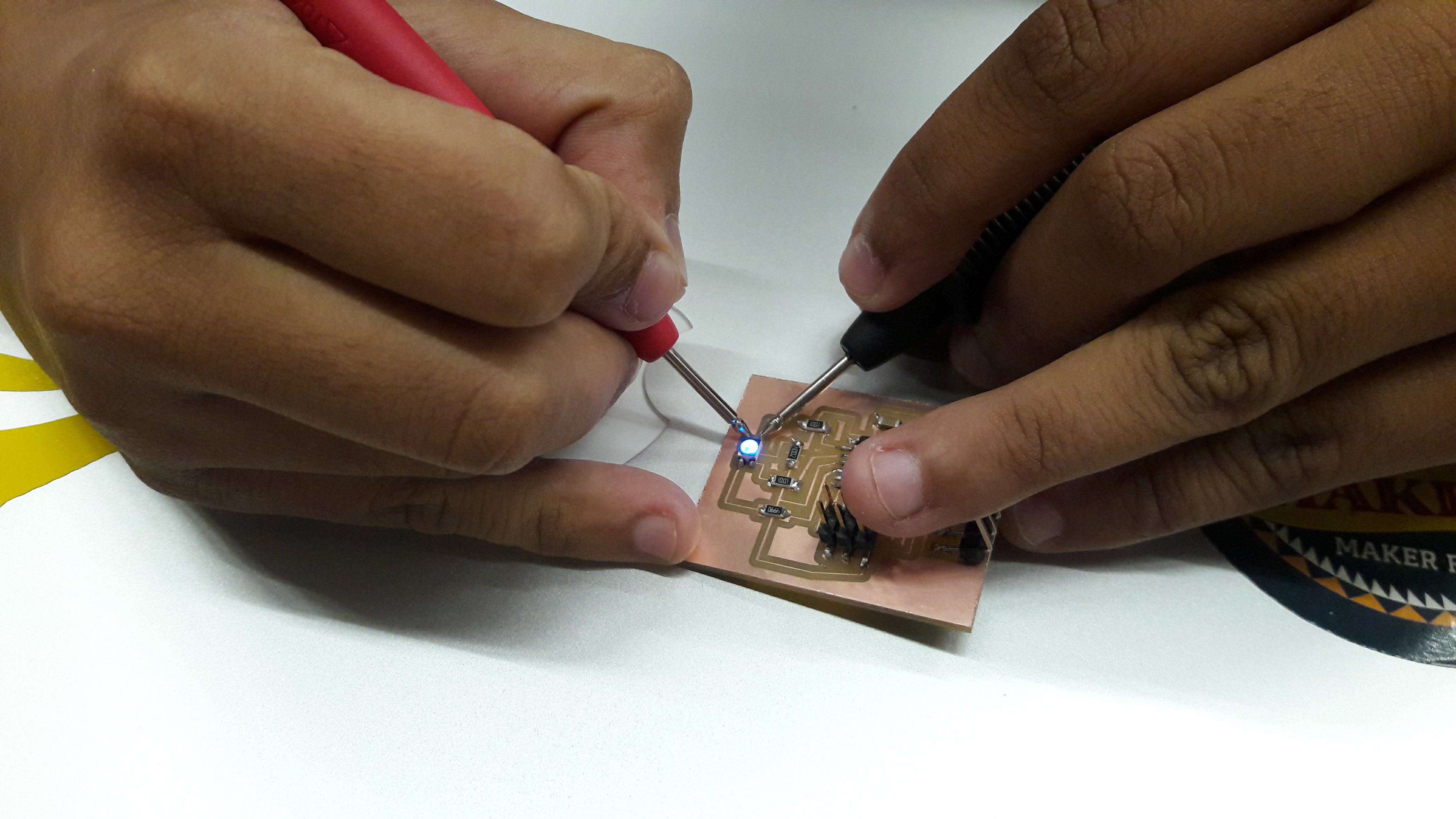
Now the board is ready to be coded. I referred the code from here and made changes according to the design. First I tested the code with rgb. The code worked properly and the rgb was bright and beautiful.
- ATTiny 44
- RGB Led
- Ultrasonic Headers
- FTDI
- Capacitor
- 4 Resistors
Connecting the components at the required pin number.
Eagle board view
I used Auto-rout command to generate the traces and made some changes in the path for making it look more better.
This happens when the board does not stick properly to the machine’s bed, the board starts moving and all the traces gets merged As the board got wasted, I milled another board with sticking a good quality tape and it milled properly. Now the board was ready to be soldered.
I tested the board with multimeter, all the connections were perfect and no part was merging.
Now the board is ready to be coded. I referred the code from here and made changes according to the design. First I tested the code with rgb. The code worked properly and the rgb was bright and beautiful.
Code of Ultrasonic with RGB
     #include <SoftwareSerial.h>

#define RX 5
#define TX 6

SoftwareSerial mySerial(5,6); // rx, tx

#define echoPin 2
#define trigPin 3
#define LEDPin 13

int maximumRange = 200;
int minimumRange = 0;
long duration, distance;
int redPin = 8;
int greenPin = 9;
int bluePin = 10;

void setup()
{
    mySerial.begin (9600);
    pinMode(trigPin, OUTPUT);
    pinMode(echoPin, INPUT);
    pinMode(LEDPin, OUTPUT);
    pinMode(redPin, OUTPUT);
    pinMode(greenPin, OUTPUT);
 }


void loop()
{
    digitalWrite(trigPin, LOW);
    delayMicroseconds(2);
    digitalWrite(trigPin, HIGH);
    delayMicroseconds(10);
    digitalWrite(trigPin, LOW);
    duration = pulseIn(echoPin, HIGH);
    distance = duration/58.2;
  if(distance>=60)
{
    setColor(0, 0, 255);  // green
    delay(100);
}
  if (distance<60 && distance>=50)
{
    setColor(0, 255, 0);  // blue
    delay(100);
}
  if (distance<50 && distance>=40)
{
    setColor(255, 0, 0);  // red
    delay(100);
}
 else
{
    digitalWrite(LEDPin, LOW);
}
   mySerial.println(distance);
   delay(100);
}
void setColor(int red, int green, int blue)
{
   analogWrite(redPin, red);
   analogWrite(greenPin, green);
   analogWrite(bluePin, blue);

}
Video of RGB Testing
I wanted to test the circuit first so I uploaded the code for RGB and checked the circuit. As you can see in the video everything is fine so I moved further by Uploading with the ultrasonic sensor code.
Video of Ultrasonic with RGB
The code for the ultrasonic is fine as you can see in the video. It is programmed in such a way that when my hand is near the sensor the RGB will show "red" light and when it is far it will show "green" light and if the hand is not too far and also not too much near the RGB will show "Blue" colour.
You can check the group work from here.