Week 12: Interface and Application Programming
This week's assignment is to write/modify an application that interfaces with an input &/or output device. I will use the Processing programming language to visualize the data from the sensor on my hello.light input board.
First step is to download the traces, interior, and the layout for the hello.light board
Traces:
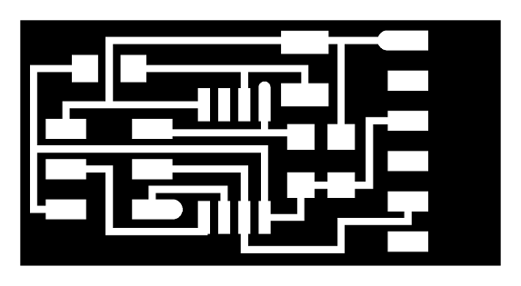
Interior:

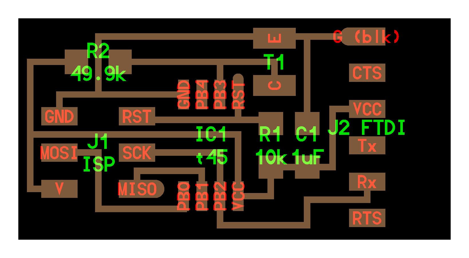
Board Layout:
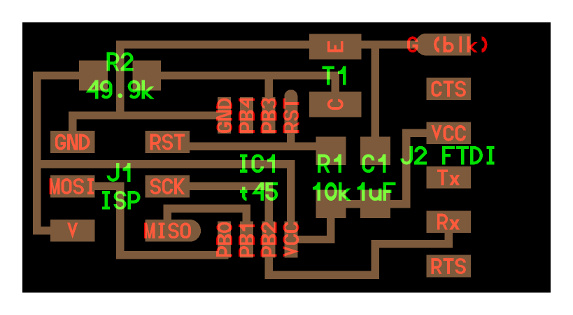
List of Components:
1 - RES 49.9k
1 - RES 10k
1 - CAP 1UF
1 - ISP 2X3 CONNECTOR
1 - ATTINY45
1 - PHOTOTRANSISTOR
1- 6PIN FTDI HEADER
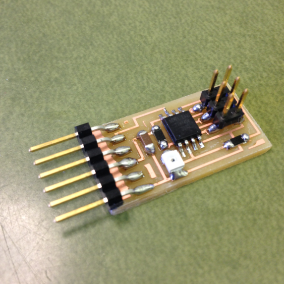
Following the same process as Week 4: Electronics Production import the traces/interior files into the Fab Module and using the Roland Modela, mill the traces and cut out the board. Once cut out, use the board layout (pictured above) to solder the components in the appropriate location. When you are finished it should look like the board below:
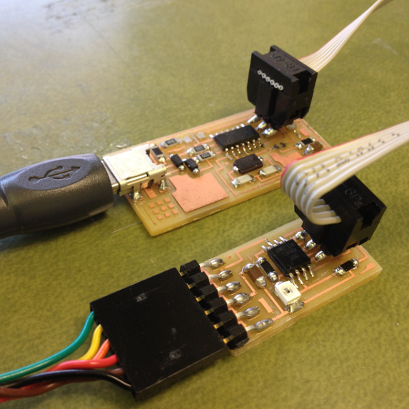
Next connect both the fabisp and the ftdi cable to the computer, and connect the fabisp to the hello.light board as well as the FTDI cable
Next download the following files and place them in a folder labeled "hello.light" on your desktop:
After downloading, open the terminal window and navigate to the hello.temp folder on the desktop by entering the following commands:
cd
cd desktop
cd hello.light
Next type:
sudo make -f hello.light.45.make
if you are successful - you will see this response from the system:
Philips-iMac:hello.light philipgonsalves$  sudo make -f hello.light.45.make

      Password:

      avr-gcc -mmcu=attiny45 -Wall -Os  -DF_CPU=8000000 -I./ -o hello.temp.45.out hello.temp.45.c

      avr-objcopy -O ihex hello.light.45.out  hello.light.45.c.hex;\

      avr-size  --mcu=attiny45 --format=avr hello.light.45.out

      AVR Memory Usage

      ----------------

      Device: attiny45
Program:      504 bytes (12.3% Full)

      (.text + .data + .bootloader)
Data:          1 bytes (0.4% Full)

      (.data + .bss + .noinit)
Next type:
avrdude -p t45 -c usbtiny -U flash:w:hello.light.45.c.hex
if you are successful - you will see this response from the system:
Philips-iMac:hello.light philipgonsalves$ avrdude -p t45 -c usbtiny -U flash:w:hello.light.45.c.hex
avrdude: AVR device initialized and ready to accept instructions
Reading | ################################################## | 100% 0.00s
avrdude: Device signature = 0x1e9206

      avrdude: NOTE: "flash" memory has  been specified, an erase cycle will be performed

      To disable this feature, specify the -D option.

      avrdude: erasing chip

      avrdude: reading input file  "hello.temp.45.c.hex"

      avrdude: input file hello.light.45.c.hex  auto detected as Intel Hex

      avrdude: writing flash (504 bytes):
Writing | ################################################## | 100% 0.55s
avrdude: 504 bytes of flash written

      avrdude: verifying flash memory against  hello.light.45.c.hex:

      avrdude: load data flash data from input  file hello.light.45.c.hex:

      avrdude: input file hello.light.45.c.hex  auto detected as Intel Hex

      avrdude: input file hello.light.45.c.hex  contains 504 bytes

      avrdude: reading on-chip flash data:
Reading | ################################################## | 100% 1.22s
avrdude: verifying ...

      avrdude: 504 bytes of flash verified
avrdude: safemode: Fuses OK (H:FF, E:DF, L:62)
Next type:
python hello.light.45.py /dev/tty.usbserial-FTGNNK5H
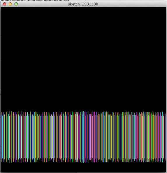
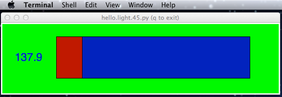
if you are successful - you will see this window pop up
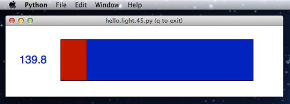
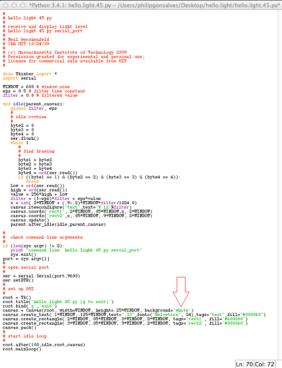
Once the hello.light board is working, now its time to write/modify the application that interfaces with the input device. I opened up the hello.light.45.py file and located the section of code with the background color.
By simply changing 'white' to 'green', saving the program, and the re-opening the visualizer, you can see the changes take effect.
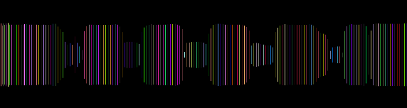
After playing around and tweaking some of the values I decided to try and run a different sketch. You can modify the sketches using the Processing serial libraries to draw different pictures based on the input coming in from the sensor.
I started out by downloading Processing and uploaded an example sketch from the Providence Lab tutorial that draws random lines across the screen, with the height varying with the sensor input
Sketch:
/**

 *  Serial Input to Randomly Colored Lines

 *

 *  Read data from the serial port and changes the color of a lines drawing

 *  across the screen the height of the lines changes relative to the values

 *  received from the sensor.

 *

 *  written by Shawn Wallace

 *  modified by Alex Fleming

 */
import processing.serial.*;
Serial serialPort;  // Create object from Serial class

      int col = 0; //starting point for the lines  on the screen
void setup() {

      size(573, 573); //set window size

      background(0); //set background color to black

      stroke(255);  // set stroke to  white

      smooth(); //smooth out the lines
   println(Serial.list());

      serialPort = new Serial(this, Serial.list()[2], 9600);

      }
void draw() {

      //if there is data coming in from the serial port

      while (serialPort.available () > 0) {

      //set the variable height equal to the data coming in.

      int height = serialPort.read();

      //to draw rows across the screen in columns

      //then wrap back to other side of the screen

      col = col+1;

      if (col > 573) {

      col = 0;

      }

      println(height);  //print the  values read from the serial port to the console

      //if the serial values are greater than 10

      if (height > 10) {

      //draw a line that increases / decreases based on sensor output.

      //adjusted for sensor values.

      line(col, (height-100)+612, col, 612-height);

      }


      stroke((int)random(255), (int)random(255), (int)random(255));

      }

      }
The first value I changed was the serialPort = new Serial(this, Serial.list()[0], 9600). To find my serial port I just replaced the 0 with a 1, saved the sketch, and ran it again. If no output was detected I repeated the steps and changed the value to the next highest number. Once I changed 1 to 2, it was successful. A seperate window opened up with the visualization.
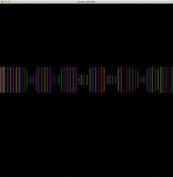
Modified certain values of the code such as background dimensions, and ran the sketch again and got a different result, with the lines spaced closer together and moved it to the bottom of the window