06 Electronics Design
This week we made a second "Hello Echo" board. This time we added a button and an LED light component in Eagle, an electornics design program. We also learned more about what various components mean and how they function. Many of us finished in time to also program the board using Arduino IDE to make the LED light up.
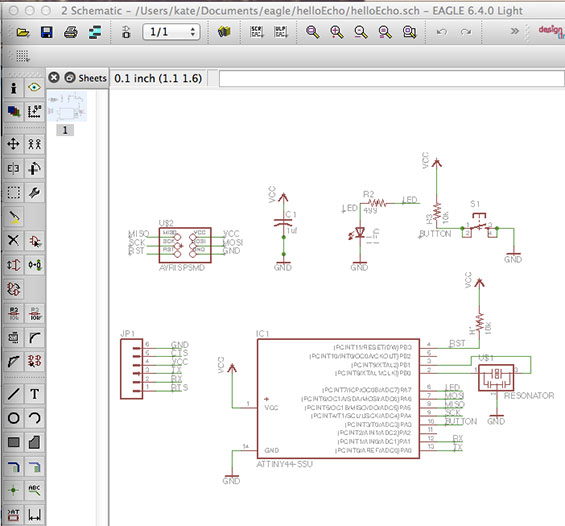
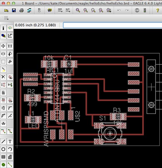
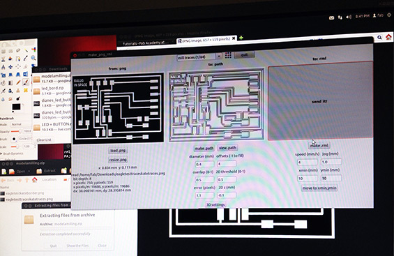
This is how Eagle looks: the top image is the schematic, where you can add components and draw traces on a board. We added the area on the top right - the button, the LED, a ground, and the required resistors. The lower image is the board view, where you arrange your components as they'll print.
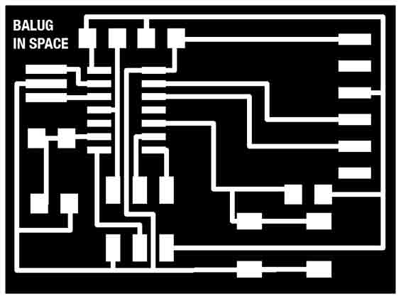
Once the file is ready to go, we export it as a monochrome .png for milling. Here we can also personalize our boards, adding a graphic or text. The text I tried to add was in font size 4... to small for the Modela!
Then we send the file to be milled.
And wait.
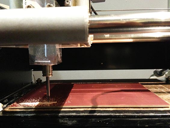
And wait.
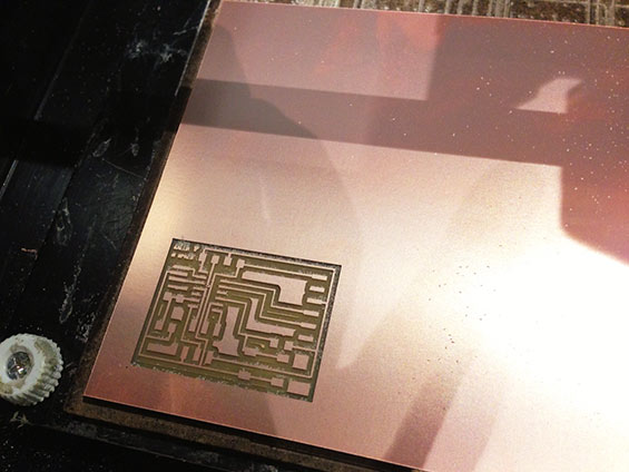
It takes about 7 minutes per board, and requires switching drill bits between milling and cutting out the board from the rest of the copper sheet.
Throw in a liattle prayer into your waiting, because if it doesn't work, you've got to do it all over again. Luckily, this one was a winner!
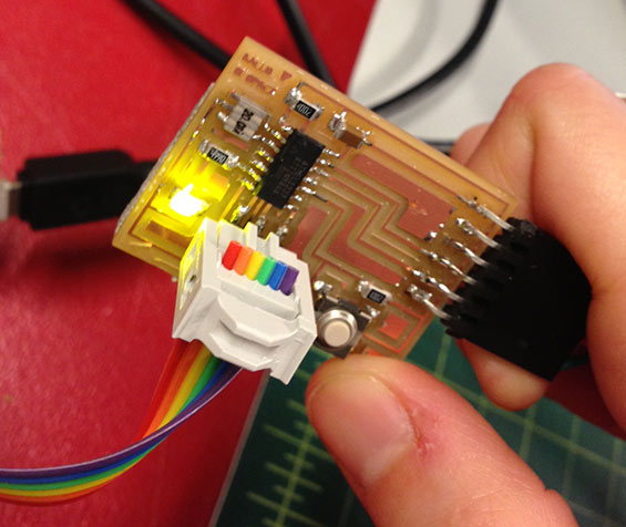
Then, time to pick out the components and get to soldering, which I thoroughly enjoy in its focused, slow but steady pace.
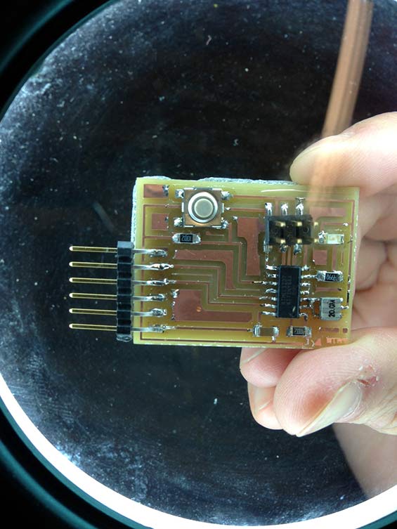
So here we have an ATTiny44 (microprocessor - the spider on the bottom right), an FTDI header (left bars) to connect to power, the button, the LED light (top right), a 6 pin connector to connect this to the FabISP programmer, a 20MHz resonator (external clock), a couple of resistors, and a ground.
Once this was put together, I revisited my FabISP using the arduino software. Before, my computer (new macbook air) wasn't reading the programmer, though other computers would read it. Once I connected it via Arduino, the computer began to recognize it - good to know!
I had a few mistakes with my board. The first you can see above - the soldering around the resonator was globbed together. The second was a loose foot on the FTDI header which needed to be resoldered. Finally, the cable ribbon cable between the two boards wasn't clamped enough in the carrier, so no connection was happening. After addressing each of these, I used the Arduino software to program the new board to turn the LED on and off, then to make it blink at regular intervals. More on this in 2 weeks!