|
Assignment 5: electronics production.
This weeks class was about making a FabISP in-circuit programmer. The electronics design was already prepared, the assignment was about learning to operate the milling machine and about soldering smd components. The milling machine takes away the copper surface of a print board, only leaving traces that form the connections between the components.
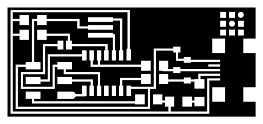
The pattern of the isp board in the board in the .png file.
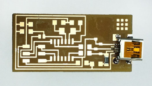
The print board with the first two components. It took some practice before we got the tiny components in place.
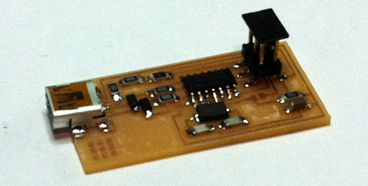
The print board with the components on it. We checked with a magnifier to see if all the solder connections look shiny. Also we checked the board for short circuits with a multimeter. Then we programmed the board according the instructions on Davids site. Done!
As a reminder I took notes of all the steps to mill the board...
Step-by-step instructions for milling the board
First mill the traces
- Place the bed with sacrificial board into the modela
- Place a piece of print board on the sacrificial board using double-sided tape
- Place the printer head on the modela
- Press ‘view’ to make the board come towards you, and the head go to the back.
- Place the 1/64 milling bit (it’s the one that has a damaged top) into the bus in the head. Slide it in supporting the bit from the side with your finger without touching the tip of the bit. - When the darker part of the tip just sticks out, tighten it from one side using the imbus. You might have to turn the bus half a turn.
- Go to the computer, download the .png files from the class 5 page and save them
- Open the terminal and type ‘fab’ to open fabmodules
- In the fabmodules select the ‘from image to roland modela’ button
- Load the .png file with the traces
- Check whether the size makes sense
- Click ‘make path’ and then ‘view path’ to check whether the tracing lines look ok
- Check the settings:
Miling traces 1/64 from the dropdown menu
Diameter = 0.4
Offset (number of traces) = 4
Overlap (between two traces for the selected bit) = 0.5
2D threshold (how it makes grey into black or white)= 0.5
Z= -0.1
Speed = 4
Jog =1.0
Min x,y = set it safe, e.g. 1 mm from the edge of the board
- Press ‘move x,y min’ and go to the modela
- If ‘view’ is deselected at the modela the head moves in place
- Lower the head by pressing ‘down’ on the modela for longer than 3s to make it move downwards. Keep pressing the button as long as you want it to move
- Stop the head when the bit is close to the board, but the head not entirely down
- Loosen the bit and help it slide down with your finger untill it gently taps the surface of the copper. Turn the bit around so it sort of skims the surface. Then tighten it
- Just to make sure, clean the buffer by pressing up and down at the same time while in view mode. The LED shoud blink for a couple of seconds. If it keeps blinking you have a serious problem and you need to have a difficult conversation with the terminalL
- Ready?
- Press ‘make .rml’ in the fabmodules interface
- Press the huge send-it button that appears to start milling the traces
- Brush away the dust to give way every now and then untill the job is finished
Then mill the outlines
- Clean the buffer: press the up and down buttons on the modela simultaneously
- Press ‘view’ on the machine to bring back the head
- Change the tool: now put the 1/32 bit
- Go back to the fabmodules interface on your computer
- In the interface click away the previous job (remember x, y min settings)
- Select ‘from .png to .rml’
- Open the .png file that contains the outlines and check size
- Bring the bit to the x,y min position, should be the same as in the first job
- Bring the bit down via the down button on the modela, press longer than 3 sec to start moving
- Level the bit: unlock the screw, slide bit down to the surface, being careful
- In the interface press ‘make path’, check with ‘view path’
- Check settings: Keep default mode in the dropdown menu
Diameter: 0.79
Offsets: 1
Overlap & 2D thr: 0.5
Error:1.1
z2D: - 1.58 (material thickness + 0.3)
!Speed!: 0.5
Jog:1.0
X, Y min: same as in the tracing job
- Press Make .rml
- Press Send it
- When the machine is done take out the part with a stanley knife
- Clean the dust and tape from the machine
|
 Astrids Fab Academy Projects