This weeks we made printboards with an output device according to Neils examples, and manipulated the code to make it do something (else). I made one with an RGB LED and one with a LED array:
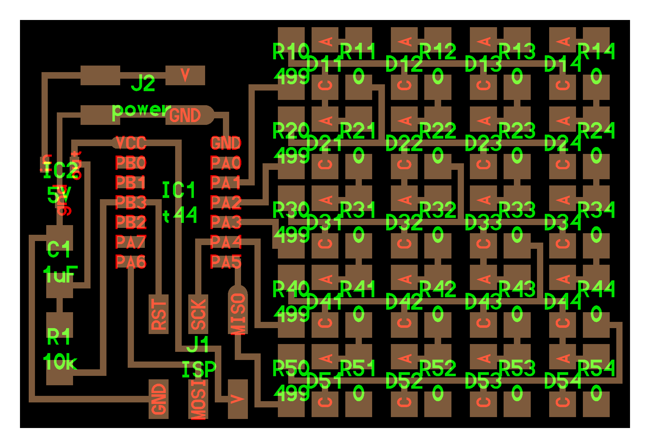
The array board uses only 5 pins to power 20 LEDs, this is a technique called Charlieplexing. For understanding how that works I can recommend reading this instructable.
Soldering the LED array The LED array board has a lot of components to solder. Bas showed me a proper workflow to stuff the board, which helped me to do the soldering job very quickly:
With the lead thread in the left hand and the soldering iron in the right hand (or vice versa if you prefer) you put little drops of solder on all the pads where the + sides of the LEDs and other components will be placed. In the left image the red dots indicate where the next solder drops should be placed:
When you have done all the rows like this, put away the lead and pick up the first tiny component with tweazers with your left hand. Reheat the drop of solder and slide in the component with your left hand. Then put away the tweazers, and take the solder in your left hand again. Heat the negative side of the component and corresponding copper pad on the board with your right hand, and add a drop of solder with your left hand. Done, go to the next component untill they are all fixed with a nice shiny drop of solder. Make sure the orientation of all the LEDs are correct. The negative side of most LEDs are indicated with a colored line, in this case you see a green stripe. Then if it all looks ok under the magnifier you can prepare the battery. Take a battery clip with a red and a black cable, and squeeze the ends into a 4 pin connector. Mark the 'ground' and '9V' holes in the connector (there will be two holes left that are empty) so you will not be confused when plugging it on the board.
Checking the connections The array board has a lot of components, and if one connection is not conducting the board will not work (or fry) if you power it. Therefore it is wise to check the connections with a magnifying glass to see if they are all shiny and if they are connected exactly as in the board example image as provided. Bas advised me to use a multimeter at the 20V position to check the voltage at some critical points:
- between the + and - poles of the battery there should be 9V; if not replace battery
- between the gnd and V legs of the power pins it should be 9V; if not check cables
- between the gnd and the + side of the IC2 component there should be 5V; if not the voltage is not being reduced correctly.
Programming the board Type these commands in the terminal:
make -f hello.array.44.make
sudo make -f hello.array.44.make program-usbtiny
Now Neils code runs, you can disconnect the cables and the LEDs will keep running until the battery is disconnected. The RGB LED blinks in different colours and the array flashes a pattern:
Manipulating the board Then it was time to manipulate the code. First I just took lines in and out of the code to see what happened and understand what each of the lines does. Each LED has a two letter 'name', and I made a cheat table to remember the names of the LEDs:
BA
CA
DA
EA
AB
CB
DB
EB
AC
BC
DC
EC
AD
BD
CD
ED
AE
BE
CE
DE
Then I copied the LED cycle 5 times and make each cycle flash a letter of my name. This is the code:
void led_cycle(uint8_t number, uint8_t delay) {
//
// cycle through LEDs to make an A
//
uint8_t i;
for (i = 0; i < number; ++i) {
flash(B,A,delay);
flash(C,A,delay);
flash(D,A,delay);
flash(E,A,delay);
flash(A,B,delay);
//flash(C,B,delay);
//flash(D,B,delay);
flash(E,B,delay);
flash(A,C,delay);
flash(B,C,delay);
flash(D,C,delay);
flash(E,C,delay);
flash(A,D,delay);
//flash(B,D,delay);
//flash(C,D,delay);
flash(E,D,delay);
flash(A,E,delay);
//flash(B,E,delay);
//flash(C,E,delay);
flash(D,E,delay);
// each LED has a two letter name, in this way you can address each
LED by flashing its letter code
}
}
void led_cycleT(uint8_t number, uint8_t delay) {
//
// cycle through LEDs
//
uint8_t i;
for (i = 0; i < number; ++i) {
flash(B,A,delay);
flash(C,A,delay);
flash(D,A,delay);
flash(E,A,delay);
//flash(A,B,delay);
flash(C,B,delay);
flash(D,B,delay);
//flash(E,B,delay);
//flash(A,C,delay);
flash(B,C,delay);
flash(D,C,delay);
//flash(E,C,delay);
//flash(A,D,delay);
flash(B,D,delay);
flash(C,D,delay);
//flash(E,D,delay);
//flash(A,E,delay);
flash(B,E,delay);
flash(C,E,delay);
//flash(D,E,delay);
// each LED has a two letter name, in this way you can address
each LED by flashing its letter code
}
}
int main(void) {
//
// set clock divider to /1
//
CLKPR = (1 << CLKPCE);
CLKPR = (0 << CLKPS3) | (0 << CLKPS2) | (0 << CLKPS1) | (0 << CLKPS0);
//
// main loop
//
while (1) {
led_cycle(75,1);
led_cycleS(75,1);
led_cycleT(75,1);
led_cycleR(75,1);
led_cycleI(75,1);
led_cycleD(75,1);
led_cycleX(400,1);
// led_cycle(1,100);
// going through the array 1 time with a delay of 100
// led_cycle(3,20);
// going through the array 3 times with a delay of 20
// led_cycle(100,1);
//going through the array 100 times with a delay of 1
}
}
Some troubleshooting Off course I encountered some trouble before everything worked. With the RGB board I did not notice that I had used another LED than was specified on the class page. The marker was on another pin so I connected it the wrong way.
For some reason it also took me a while to get the array board working. In the end I flashed the code again and it worked - don't know what happened...
 Astrids Fab Academy Projects
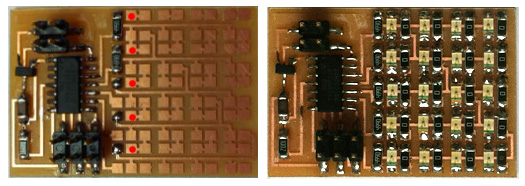