RoboDuck 3000
Dear reader, welcome to your version of Roboduck 3000.
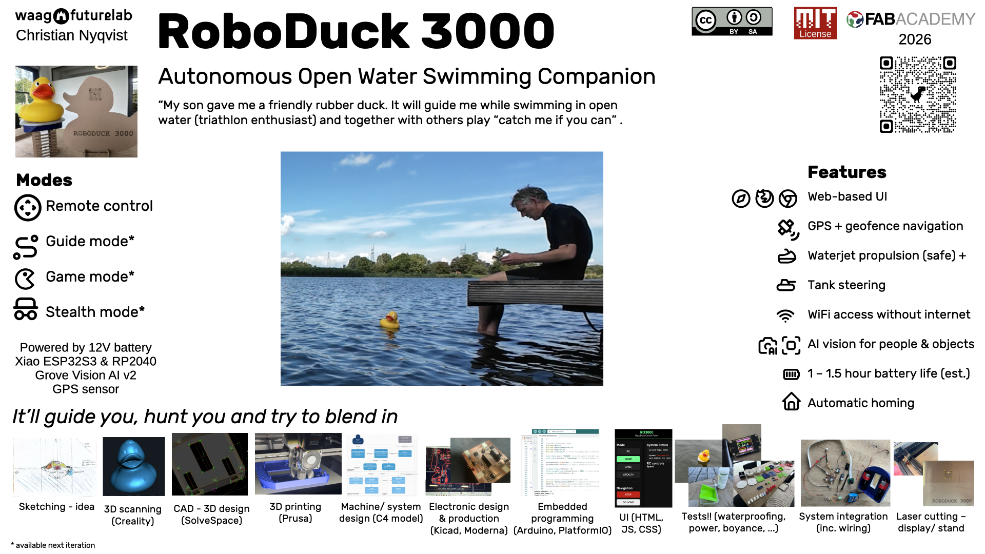
I created RoboDuck 3000 as an autonomous, water-jet propelled swimming companion disguised as a classic yellow rubber duck (which I got from my son). Basically It will guide you, haunt you and try to make friends with wildlife.
It combines GPS, AI vision (Grove Vision AI v2), custom made PCB's, WiFi web interface for remote control, custom 3D-printed parts, laser cut display stand and tank steering with 2 12v dc motors for the 2 waterjets. I made it with a couple of non-functionals in mind:
- designed for open water (like the river Vecht where I swim regularly).
- should not cause any polution
- be as stable as possible
- be able to run at least 30–120 min on the battery (depending on the mode)
- should be switched on/off by putting the duck on the platform or off
More info about this in week 2 of my journey and system overview
Anyway, if you're interested, this page will help you how to realize your version of this duck. And if you want to read my whole diary and other info please see any of the following pages.
- My journey
- Journey of scope
- System architecture
- Decisions
- Journey of bill of materials and software (but repeated below)
- Scans I made
Why did I do it and is it for you?
I created this device as part of my final project during FabAcademy 2026. At that time I had no specific audience in mind. Also not for fame (although it would be nice of course if my duck will get some fame while floating around and pretending to be a real duck).
Looking back this project might be of interest to you if you fall in one of the following categories:
- You like to swim/ be in the water and look forward of having a rubber duck swim in front of you and/or have some smaller kids and having a duck that is trying to catch them sounds like fun and/or just think this is fun (in any case you'll never swim alone again).
- FabLab maker/student, and/or part of a maker community in general, because this is reproducible and might help you design a better version
- Educators who want to use this project to teach about waterproofing 3D prints, IoT, voltage conversion, communication protocols, system integration
Has this been done before?
Well probably somewhere on this planet somebody has made this .. or at least some version of it. I did look at other FabAcademy projects like that of Mkhitar's submarine (2025) and various duck/RC boat builds. I ended up reusing an existing duck instead of printing one in 3D. First of all it's a small duck but pretty big for a 3D printer and secondly from a filament pollution point of view I rather reuse something that is already there. But hey if you want you can actually print your version based on the scans/STL file I made (see download section).
Regarding the propulsion that was easy as I did not want to get my fingers in a propellor. Also waterjets can be nice and quiet as well. But no, only examples I saw were with RC racing boats, not with with fake ducks. Yes there are a few examples on sites like Printables but at that time I was not yet familiar with the possible strength of 3D printed materials so I choose to buy that from a shop.
And related to AI vision ... I didn't see this yet but on the vendors site (SeeedStudio), and in general object detection using neural net models, but of course I knew this was possible because of their example in other non-water projects (also because I teach machine learning).
See also inspiration from others.
What sources did I use?
A lot! But if I have to summarize:
- Global and local (see my final presentation slide were I mention them all)
- SeeedStudio docs, SenseCraft, Arduino/ESP32 libraries, SolveSpace, KiCad, PrusaSlicer, VCarve.
- Peer input from Heleen and Remco, YouTube explainers (like about Dichtol sealing), datasheets (especially from DigiKey and vendors), and also Grok/ChatGPT explanation, exploration and debugging
- Materials I got from our FabLab inventory and I bought a lot online (AliExpress, Amazon, Bol.com).
So again what did I design
I designed the following parts:
- Hull/platform/keel with integrated motor mounts, battery holder, waterjet inlets, USB-C case (using SolveSpace).
- A lid with magnetic attachment points to hold the duck in place with a pogo-pin on/off switch at the back (also using SolveSpace)
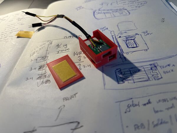
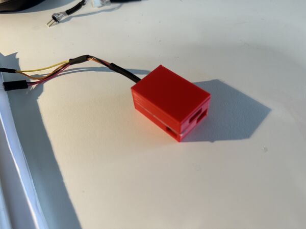
- Dedicated PCB for navigation unit that runs on a
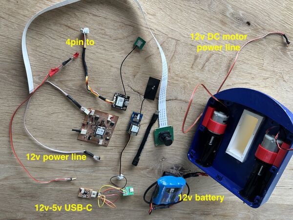
Xiao RP2040with MOSFETs for providing current to the 2 12v DC brushed motors, 2 voltage regulators (12v -> 5v; 12v -> 3v3). The PCB connects to a GPS sensor (UART communication) and to the "brain" (Xiao ESP32S3 that sits on top of the Grove AI vision v2; communication via I2C) - Wiring
- Software architecture (described as a C4 model) that shows how each component interacts with another including a UI for remote control via Wifi access point coming from the ESP32S3
- The communication protocol between the micro controllers
- Code for the
tank steering
More detail can be found in:
What materials and components were used? Where from? How much did does it cost me?
Always good to know.
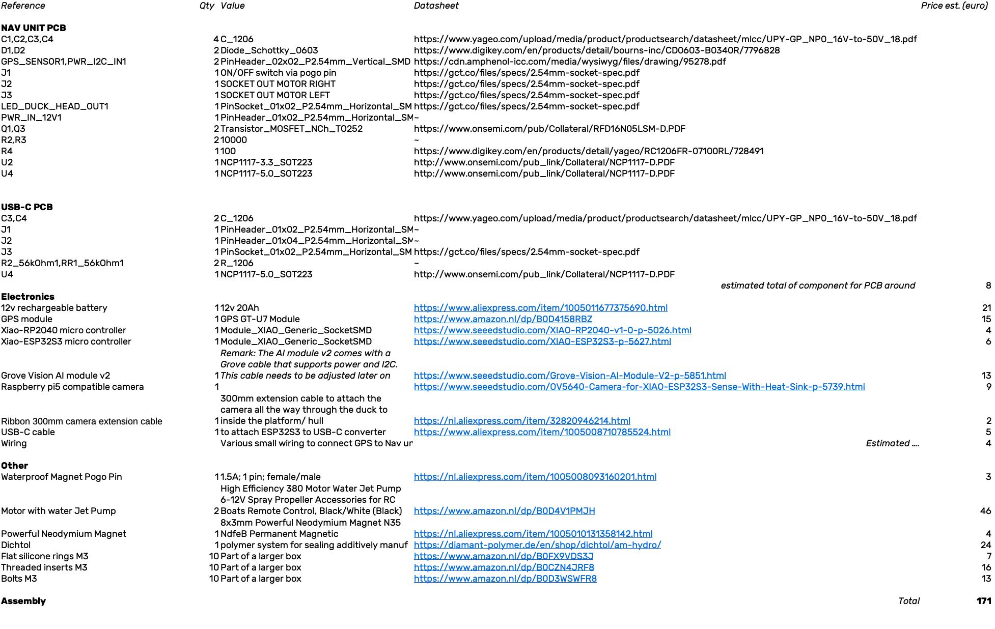
Screenshot of the BOM spreadsheet
See the full details in bill of material.
Remark: from this list I've excluded detailed pricing for the smaller components from our FabLab and the rubber duck itself
To summarize the big expenditures:
- Electronics: Xiao ESP32S3, Xiao RP2040, Grove Vision AI v2 + camera/ribbon, GT-U7 GPS sensor, 12V battery, 2x 12v DC brushed motors
- Mechanical: waterjet pumps, magnets
- Other: filament (PLA/PETG), inserts, bolts, silicone kit
Total estimate: between €150–200
Remark: actually the 2 waterjet's were most expensive. I've seen printable 3D versions so you could maybe use that yourself
What parts and systems were made (and are to made by you)?
In short:
- The hull, lid, battery holder, motor mounts, GPS holder, USB-C holder and AI holder were all 3D-printed
- Waterproofing (using Dichtol) of the hull, the lid and the battery holder
- The
Navigation PCB(around 66mm x 55mm wide); and it needs to be soldered - Code/software written in C to provide a UI via Wifi (index.html with javascript, CSS and HTML), interpret the GPS info (UART connection), let the
brainmanage the system as a whole (via I2C using a self invented protocol) and "talk" to the AI Vision module to ask it to detect object and power the motors using PWM using a tank steering algorithm. Last but not least many standard AI vision models can be used but for the future time has to be spend to train your own and/or find a good dataset for it - A (better) seal to close the lid
What tools and processes did I use (which means you have to learn)?
For CAD (computer aided design) I used Solvespace. It looks like a light weight kind of tool but for me it was easy to understand as a newbie. It provided parametric design and working with assemblies and is able to export to a couple of standard formats. Of course I you're experienced in another tool than use that but it does mean you have to convert the design files.
For fabrication I mainly used 3D printing (on my personal Prusa CORE ONE+) but any other 3D printer that understands STL will do. I kept the overal size of the platform parts to a minimum (around 210mm x 180mm) so it can be done with a lot of printers.
For electronic design and production I used Kicad (schema and PCB editor) and exported those to Gerber2PNG to create PNG's that I used with Modsproject.org. The output was then sent to our Fablab's MDX20 from Roland.
Soldering I did at the lab with a solder iron and a heat gun (that comes in handy to flux those MOSFETs and voltage regulators and make it nice using shrink tubes).
I programmed C using the Arduino IDE, for the ESP32 family, and PlatformIO within Visual Studio Code (for the Xiao RP2040). I found the libraries easier to manage within Arduino but likes the IDE from Visual Studio Code better. At some point I found it too time consuming to switch.
For the UI is created one index.html file (with HTML, CSS and Javascript) that I uploaded to the ESP32S3 via LittleFS (small file system). The javascript code runs in any browser and 'talks' to the 'brain' (ESP32S3 that also acts as Wifi access point) via web sockets; and vice versa.
Although not really mentioned as a skill but I spent quite some time on trying out stuff; assembly of parts; etc..
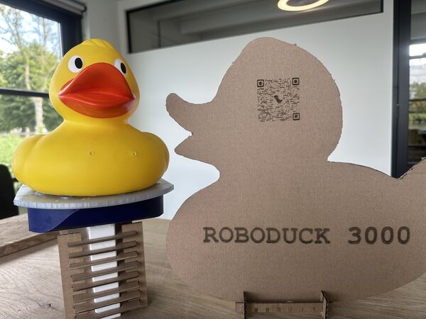
And finally CNC; I used our CO2 laser cutter to make a stand/ display out of carton. I first wanted to make it out of plexiglass but as the design might still change I'll carton for now (is also friendlier to dispose of and less expensive in this trial phase). The idea is that people will see it at home and via the QR-code can directly access all info.
What questions were answered? In other words how did the prototyping phase help me sofar?
I want to refer to all the decisions I've made. There I explain why I took certain decisions and therefore also which questions I answered for myself. Please also read my testing efforts starting week 12 until 19 that gives you more details about waterproofing, motor thrust, range, ...
But to give you an idea ...
First of all this light duck on water can be very wobbly. So keeping a long batteryholder as keel those help to minimize this. Secondly after a first test I decided to reduce the volume so that the duck would become part of the water line and not sit above it. My latest test shows that I've succeeded. Also less volume means less mass and therefore a possible higher speed. And to keep the duck in place I use magnets in the lid AND in the duck itself. This also worked well.
Regarding waterproofing this was and still is an issue. Not so much the closed parts as Dichtol works very well. I'm talking about the integration of the lid and the hull. As I want to reopen the lid for updates of code and other stuff it is a big area to cover and somehow I did not manage yet to be 100% certain that no water comes in. This is also difficult to detect as the lid is non transparent. From ealier tests I've seen that water does not come in from the bottom and/or the waterjet's.
Tests have shown that the propulsion with waterjet's is safe for my hands and relative quiet.
I'm pretty amazed how stable the Wifi of this little ESP32S3 is (once it got it's own power supply of 5v). Yes I sometimes have to refresh the browser page but other than that it is actually very good; good range even partially submerged.
I switched from the ESP32S3 to the AI Grove module v2 for object detection and has been a good choice as well. Yes it consumes a bit more power and is more expensive but it brings so much dedicated speed that's actually a no brainer now.
Lastly but not least I figured out that the ESP32s3 is best of using it's own 5v power supply via USB-C and that my original power bank stops when a tiny micro controller doesn't ask for enough power. it all gave me great inside into MOSFETS' and voltage regulators to power the entire duck with just 1 12v battery.
So everything is fine then?
Well no. Yes it floats, can be controlled via a web browser and provides tank steering via remote control buttons. And yes the duck actually stays on the lid and doesn't fall of. And yes the waterproofing with Dichtol works on the surface. And yes I solved some questions about power supply (see previous section).
BUT the last test it basically filled up with water from somewhere. Despite all the work and tests I done the connection between the lid and the hull has to be redisgned. So yeah at the moment that is the number 1 improvement to make. Vaseline works but it's messy.
And what needs to be tested is the whole camera to detection process. I know this can work as I have done tests with it but how it would behave in waves and what AI model to use or to train, that's still unclear. I have seen datasets with pictures of people wearing caps in the water they use for swimming pools; so there must be material. Also see [week19](../assignments/week19/week19.md#whats-working-whats-not and week18.
Oh and a low battery warning would come in handy when the duck is somewhere out there.
If I'm happy now?
Well again yes and no. I'm sad that I did not finish all the modes of operation but I kept working using the principles kill your darlings and kept a strict scope. Please see my journey of scope page for the full story. But looking back I would say that the last weeks I was primarily focused on:
- [ ] Get the duck on the water and make it float (waterproof)
- [x] Make sure the duck doesn't fall of
- [x] It can be controlled via tank steering to go left or right; faster and slower and stop using the web interface
- [x] Make it safe to use
- [x] Make it is as quiet as possible
- [x] Make it easy to attach or detach the duck
- [ ]At least one hour run-time
Again I did not have the chance to test the power duration because well water came in. But I met most of the targets and I managed to keep my eyes on this list and not deviate into other thing that came into my head (like completely change the desing or do something completely differently or recreate the PCB's); no change without first testing what I already have.
So what's next? What happens if you want to pick this up?
You are going to have your hands full, that's for sure. But I'm completely fine with it; this is one open source project. But please do me a couple of favors and adhere to the MIT2.0 license for software and CC-BY-SA 4.0 for documentation and media).
Other than that I really don't care. I think this is a fun way in education to enhance spiral design, learn how to test and integrate things. My plan is personally to make it more like a catmaran for balance and to really work on the guide mode and later the AI mode. Maybe I'll change the materials and go for epoxy (as it's lighter than I though it to be) but who knows.
For other ideas see my dissemination.
Still interested ... let's get you started ...
Let's get you started
First of all download this zip. It contains design, code~~, STL ~~& Gerber files.
Based on feedback from my global evaluator I've know added the DUCK STL file. However it had to be split into several pieces because of it's size
To make one file again copy these files into the same directory and use
The duck.stl file contains the STL file of the whole duck.
Materials
Then get yourself the list of materials (source)
Software
The software you need is all free. Of course you can just use the Gerber files to make the PCB's on your own milling machine and use the STL files to print 3D. But if you want to modify/edit then please see section Software.
Hardware
To make/ assemble all this you need:
- 3D printer where I used PLA/PETG as filament
- PCB milling machine
- Laser cutter if you want to make the stand/ display
- Soldering iron, heat gun, multimeter
Step 1: 3D print the parts
Use the STL files, use PLA or PETG and print each at 0.2 mm layer height, 15–20% infill, no supports for most parts:
- the hull (lower platform)
- the lid
- the battery holder (which also acts as keel)
- the motor holders (x2)
- the AI module holder
- the GPS sensor holder
- the nozzle extensions
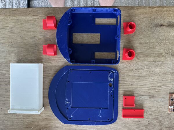
your result should look similar to this
Start with the hull at 100% and see that the waterjet's you purchased actually fit.
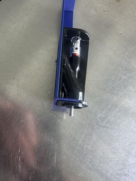
section of the hull; this is how the waterjets should fit
Then try to fit the battery holder.
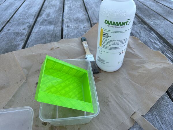
After printing make sure to make the outer parts waterproof with Dichtol; use multiple thin layer.
Remark: please see my photos
Afterward place the magnets on top of the lid and duck bottom. For the lid I used a solder iron.
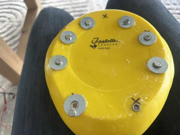
By the way at the bottom of the duck I used spacers so that the duck can move a bit while still staying attached to the hull.
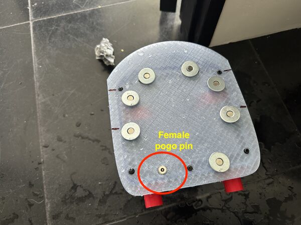
Also make sure the female part of the pogo-pin is fixed to the outside with wires going inside the duck later on.
Don't forget to put the inserts inside the hull for later.
Note
For inserts ... Set the solder iron at around 15 degrees Celsius higher than the temperature that was used to print with the filament. In my case I used 190 degrees because I printed the hull with PLA (170 degrees Celsius)
Step 2: Make the PCB's and wiring
Gerber files are already there. So any milling machine is fine or order the board. But if you want to make layout changes first then you need Kicad.
Once you have the board solder the components on it (footprint for the Xiao RP2040, MOSFETs, regulators, diode, capacitors, resistors, male and female).
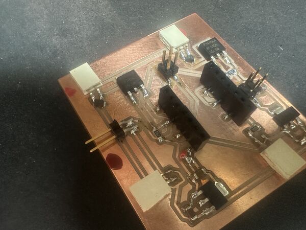
soldered navigation unit/ pcb
See the BOM which states what components you need.
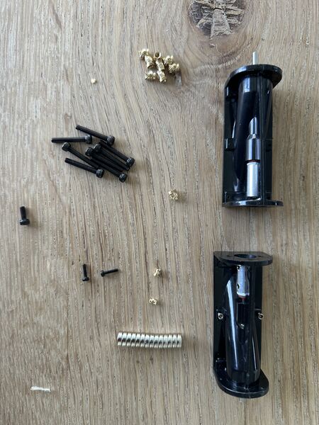
Part of the list are the waterjets, M3 bolts and inserts, magnets
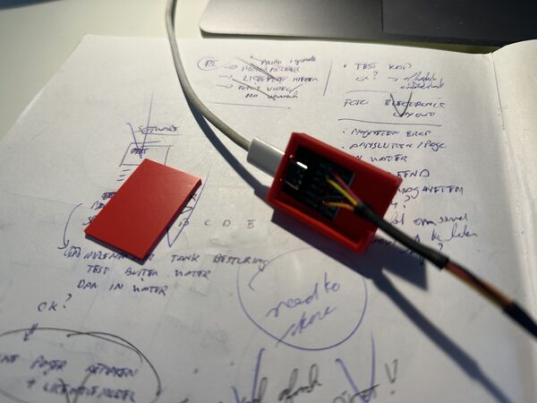
Then do the same for the small 12v-5v USB-C PCB (meant to convert 12v into 5v) and attach that to the USB-C board.
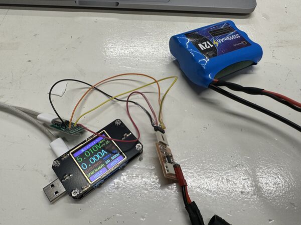
small test proofs that it works; should say 5v
Make the wiring to connect the GPS sensor to the navigation PCB, the Grove cabel to the navigation PCB, 2x wires to provide 12v to the motors and to provide 12v power from the 12v converter to the navigation PCB.
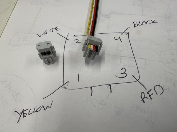
Both the Grove and the GPS are connected to the navigation unit via these female 4-pin connectors. This is the Grove connection example. But the GPS is connected in the same way
Make a small connector to later attach the pogo-pin wires to the navigation PCB.
Also make sure to make a small connector to attach the 12v battery to the USB-C converter. This one will then provide power to the navigation unit and the USB-C connector.
Final results should look similar to this
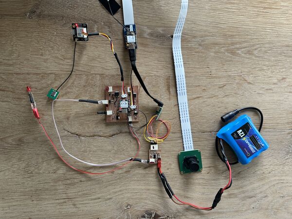
All put together ... should look similar to this
Regarding the wiring some tips from me:
- I used a squeeze tool for the connections (see week19 photos).
- Make sure that the wires are not to heavy as they cause strain on the PCB's; or take care of strain relief
- I used heat shrinks to less expose the wiring; make it also a bit water proof
Step 3: Additional water proofing
I still find this the most trickiest part. Although you have already used [Dichtol] to make the outside parts waterproof you also need to think of the inside. So just do these things:
- Seal the attachment of the waterjets to the inside of the hull. Use silicone and/or small bolts
- Grease the axis's of the waterjet a bit to prevent water coming in that way
- Attach the electronics inside lid and keep it as high as possible. Use the 3D printend mounts and double sided tape (or something else that makes it sticky)
- GPS has it's own mount and has to be place at the bottom because of space. Attach the atenna at the back.
Please test bit by bit in a bath tub first. You can read about my experiments (I used tupperware first) in week18 and wee19
adding some grease to the axis's of the water jets
using small bolts that came with the waterjets to tighten them to the hull
use silicone kit to attach the nozzles and put some kit around it for sealing
Step 4: Software
Please see this section to install/ update Arduino IDE and PlatformIO.
So you need the Arduino IDE to upload the code to the ESP32S3 which acts as brain/Wifi access point. Then, and this is really important, you need to upload the index.html file to the ESP32S3 using LittleFS.
For the navigation unit, to program the RP2040, I used PlatformIO. I'm not saying it can't be done with Arduino IDE but even on the SeeedStudio website they mention the use of PlatformIO. After this you can basically run everything; it should work.
Regarding the AI object detection. I don't have a model yet. And there are different ways to upload a model to the Grove vision model v2. Keep you posted.
Step 5: Assembly
There are a few things left. Now that the waterjets are attached it's time to mount both motors with the motorholders.
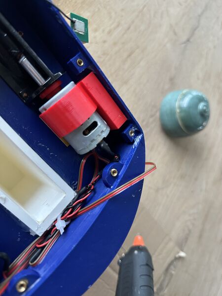
motor holder mounted and in line with the axis!!
Then put the battery in the keel, hook up the wiring.
sandwich the USB-C board ..
put the PCB beneath it
end result looks something like this
Then the most important part is the attachment of the lid to the hull. So yes there are bolts that go from the outside into the inserts; use a 3mm washer of silicone for this! But then use vaseline only to fill the gap between the lid and the hull. It is a bit messy but for now it's the only method that has the most chance of success.
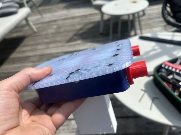
at the end should look something like this
Test the balancing of the duck, for instance in a bucket.
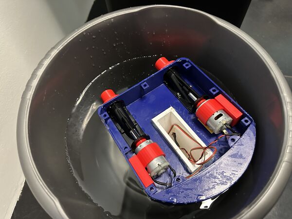
also nice to test the sealing
You should not need extra weight. But if you do there's some space left in the keel.
Step 6: Test!
Ok now you have a duck sitting on top of the hull ... first turn it on (if not already). Then connect to the wifi, open your browser and open the index.html page. The UI should say you're connected and you should be able to make the motors run in RC mode. Also , by turning left or right, you should notice that there's a difference in sound between the motors.
The GPS sensor should be blinking at the beginning; means it has power.
Then go to a bath tub or calm water outside and try it for real. Keep the duck near you so that you are able to get it out of the water if something strange happens (Wifi gone, no power, ...).
Final remarks
Currently the duck only suppports RC mode; meaning you are still in control. That's mainly because it took me a lot of time to make it waterproof. And even that is not perfect yet. So again vaseline works but it is messy. I think a custom silicone seal is better for long-term use.
Also my next iteration would be to use a catmaran design to even lower the body of the duck and make seperate bodies that are sealed. So the change of the electronics flooding will be less. And I expect more speed  Furthermore I would like to get a notification when the duck is low on power.
But anyhow, you now have everything I used to get my duck floating and controllable. So enjoy the making and using. In the mean time I'll be working on improvements and publish them here.
If something is unclear, check my journal; especially the last weeks.
Finally, feel free to fork, improve, and share your version. Tag me and let me see your RoboDuck in action!