Final project journey (all weeks)
Note
Dear reader. This page can be seen as a journey that shows my progress related to my final project; more or less seperate from my weekly assignments. There might be some overlap of course. Related are a number of other pages regarding specific topics which are mentioned below.
Week 01
The last couple of months I collected a lot of ideas.
Based on video's / work we saw during bootcamp, the local session, I got inspired to try to make it big but not too big.
Swim monitor
Every Saturday morning I go to the indoor pool to improve my swimming technique / speed. I always swim in the 2nd lane (whereas 6 being the ones for the masters). To improve I need to focus on technique and then speed. But swmming around I've no idea of how my body is floating in the water. And speed drills? Actually I hate those.
Of course I followed a course and was once filmed in the water using a camera on a stick; whereby a coach walks along side to film, you. But that has been a long time ago. And it is both costly and time consuming to do that again.
Regarding the speed drills. Yes I have a watch but Ihave to manualle activate and deactivate it. So I'm always starting with one hand on the other, give myself some speed and the end I have to find the right button again. Depending on how good I do this, the speed measurement is kind of inaccurate.
What if there was a way to (more accurately) measure my speed and make get frequently inside into the way I swim?
Solution
The [swim monitor] is a system that enables swimmers to:
- Track their speed, lap time, distance while swimming
- Be challenged/paced by a pre-programmed exercise
- Compete with another swimmer (gamefication)
- Afterwards see how they moved through the water
Visuals/ mockups
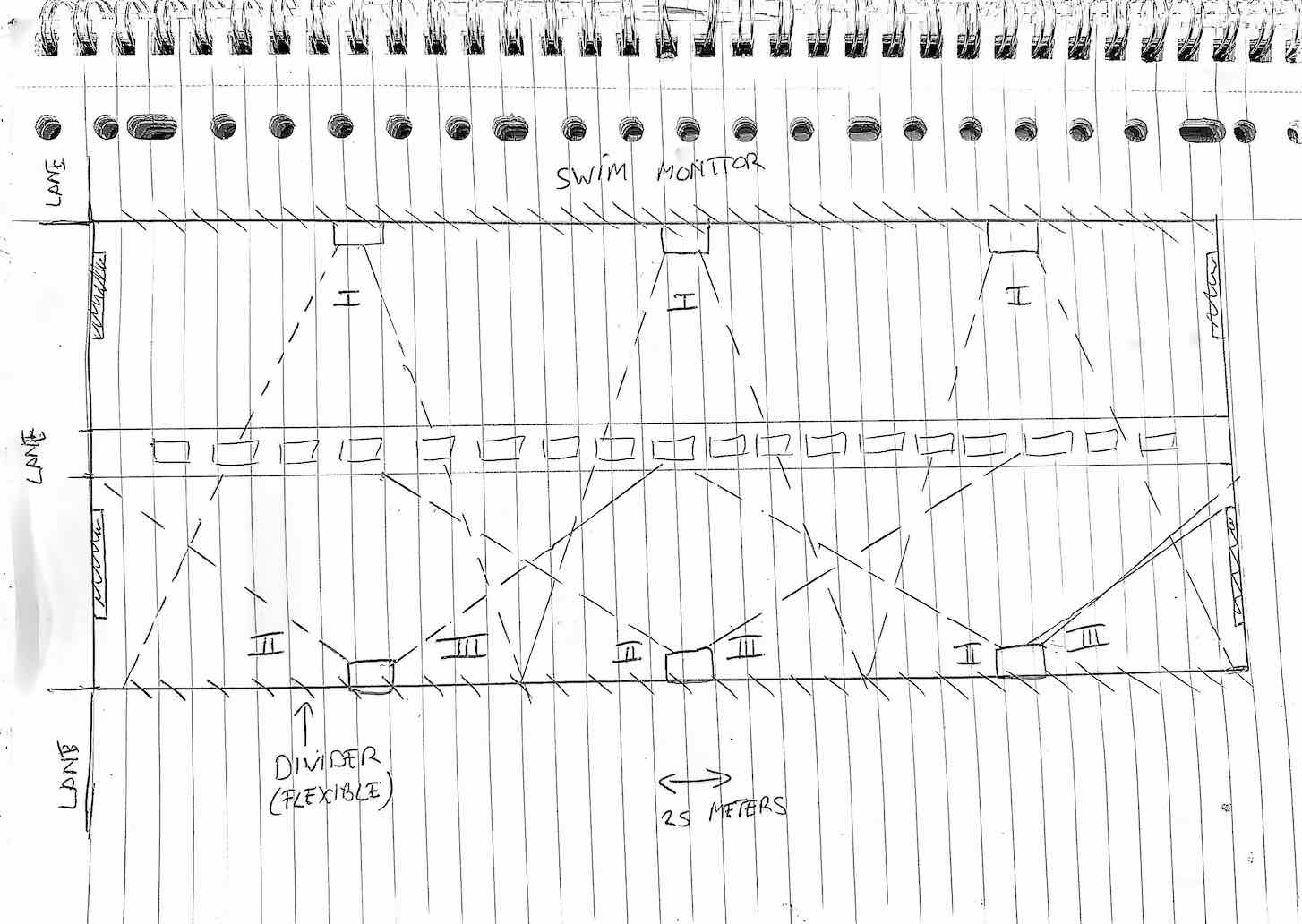
The [swim monitor] is a system that consists of multiple parts:
- Start/ stop (on both sides of the pool) that the swimmer can use to start/stop the monitor
- Lap monitor that keeps track of time, speed
- Pacer that shows how fast a swimmer should swim to meet his/her criteria
- Camera that films a swimmer from the front, side and behind
- Storage that combines timely data with visual data
Non-functionals
- It has to be safe especially around/ in water
- It is not allowed to pollute the water in any way (pool water is clean water)
- It should be possible to install/ deinstall in 10 minutes time (as other people might need the pool)
Open water buddy
I personally like to swim in open water whether it is to improve my distance or just to cool down. Usually I do this in a rive ("de Vecht") which is very near by. This river is very popular and, especially in the summer, populated with boats.
So when I swim a longer distance I'm constantly looking around to navigate but also to look around whether boats actually see me. And as I swim alone there is nobody who can take a picture of me (just for fun later on).
And when I'm in the water to cool down I usually get out quit quickly as I have no fun just being in the water; I like to do something. Even if I'm with one of my kids throwing a ball, it gets boring after a while.
What if I could have buddy that guides me and plays with me in the water?
Solution
The [Open water buddy] is a device that:
- Shows you the way (pre programmed route/ geo-fence)
- Tries to catch you or any other person that is close by (like a shark)
- Follows you around while you swim
- Monitors you while you swim (distance, photo, video)
- Randomly goes any direction so that you have to catch it
- Can be set to stealth mode to film wildlife
- Comes to you when needed
- Can be controlled remotely
Visuals/ mockups
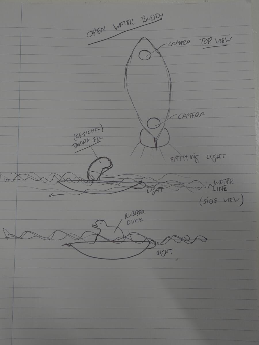
The [Open water buddy] is a device that consists of multiple parts:
- Simple interface to activate a function / user feedback
- Camera to film and take photo's
- GPS tracker for loaction\
- Light(s) for guidance / protection
- Intelligence to recognize people/ objects / birds
- Storage that combines location data with visual data
Non-functionals
- It has to be safe especially around/ in water
- It is not allowed to pollute the water in any way (although it is open water)
- It should be small/ strong enough to be thrown away (like a ball)
- It should be quiet
- It should be possible to put a shark vin in top
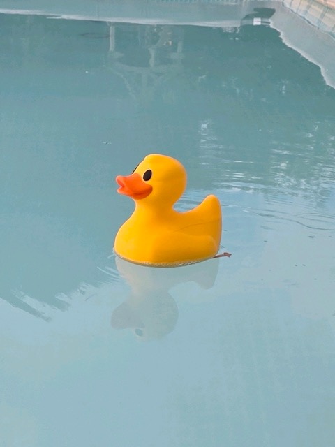
- It should be possible to put a yellow rubber duck on top of it
Week 2
I thought about creating a new page but just updated this one for now. Biggest decision is that my final project will be, what I now call, the Open Water Buddy. The main reason: I have no idea how to make it  . Sounds silly but what the heck; I only live once. First change is the working title.
UWO
Udentified Water Object. Which in a sense does not do justice to what it will be able to do. To better help me design I will decribe it's functions from a users perspective. I will therefore call this person "User".
The object supports 2 main type of modes: normal and game mode.
NORMAL MODE
Scenario 01: GUIDE ME
- User wants to go for a swim
- User enters the water and turns on UWO
- User selects "GUIDE ME"
- User sets total distance in meters
- User sets interval distance in meters
- User selects "ACTIVATE"
- UWO starts moving away from the user and keeps a safe distance
- User start swimming
- UWO signals when the total/ interval distance has been reached
Optional:
- User selects photo on/off at interval
- User selects video on/off
- User selects continuous or interval/duration in seconds
Scenario 02: FOLLOW ME
Basically the same as GUIDE ME only now the user is followed by UWO.
Optional: - User puts a shark vin on top of the object or a rubber duck
GAME MODE
Scenario 03: CATH ME IF YOU CAN
Looks similar to "GUIDE ME". Object moves away from the user. Difference is that the movements of the object are random but always meant to get away from the swimmer. Of course you can set the maximum radius in which the oject is allowed to move. Also the maximum speed while moving.
Scenario 04: JAWS
Looks similar to "FOLLOW ME". Object tracks the user but tries to catch it. There is a multi-player mode which means that it will try to catch any swimmer it can. Again here you can set a max radius and max speed while moving.
WILDLIFE MODE
- User wants to film wildlife on the water from nearby
- User turns on UWO
- User selects "WILDLIFE"
- User sets total radius in meters
- User sets total time in minutes
- User selects "ACTIVATE"
- User puts UWO in the water
- UWO starts moving away from the user away from the shore
- UWO goes into stealth mode
- UWO moves towards wildlife
- UWO films wildlife
- UWO returns to the starting point once time is up
Non-functionals
I adjusted my non-functionals accordingly
- It has to be safe. This means
- no sharp edges that can cut you
- soft impact if you get hit or you hit the object yourself
- no change/ low risk of an electric shok when you touch the object (especially in water)
- It is not allowed to pollute the water in any way (although it is open water)
- It should be small/ strong enough to be thrown away (like a disc/ frisbee)
- It should be quiet when in stealth mode
- so animals are not disturbed or spooked by it
- It should be self-supporting regarding energy
- at least 30 minutes when in game mode
- at least 2 hours when in guidance mode
- at least 4 hous when in stealth mode
- It should be difficult to detect it
- only external sensors are above water
- overal height above water should be kept to a minimum
- It is able to put itself in an upright position
- It should be possible to attach special accessoiries on it. For example
- a shark vin (game mode)
- a rubber duck (stealth mode)
- It's direction should be clear for other vessels on the water when it is dark
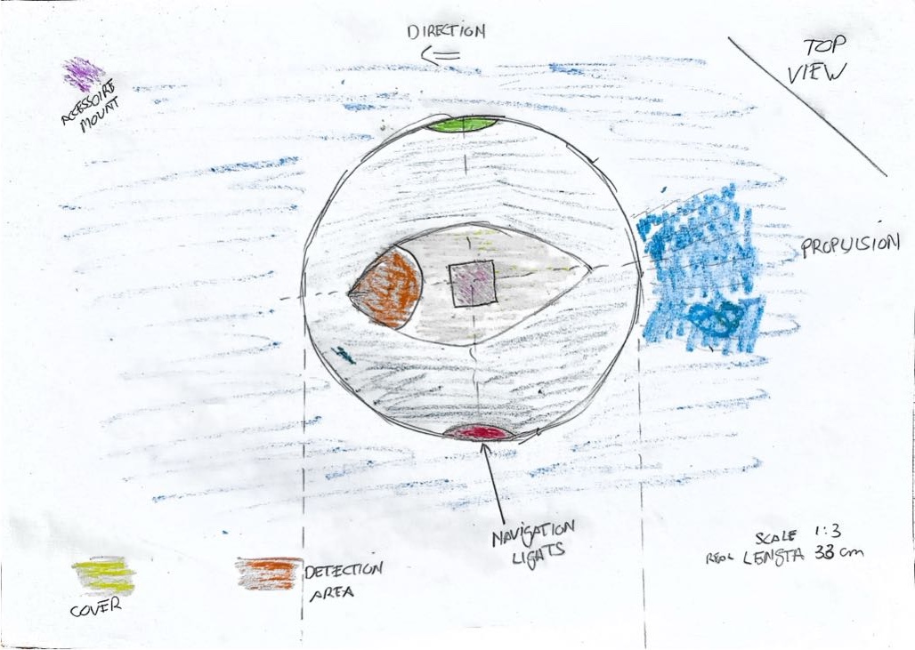
System integration
UWO as a system will consist of several subsystems.
UX
Imagine being the water; maybe the user already has goggles on. This means that the interface should be easy to use and it's information clearly visible; even when it is dark(er). Rotating knobs? LED display in numbers. On the other hand may be the interface should be outside UWO. This would make it lighter? But what if you want to change some stuff while you are swimming. If the UX is outside how do you operate it then. Hmm..
Navigation
Based on the directions from the user this subsystem is able to navigate in the right direction, the right speed. It's inputs are:
- GPS location
- Object detection (distance in meters, direction)
- Swimmer detection (distance in meters, direction)
- GeoFence
- Mode/ scenario
It uses this information to pick a path at the right speed. For instance depending on the scenario it will I go toward or away from a swimmer.
While it is navigating it will output traveled distance in regular intervals.
Awareness
This subsystem is all about detecting objects; surroundings. It's input are:
- GPS location
- Map data (water side, buoys)
- Camera/Image feed (maybe 360?)
Whether the camera feed is continous or just images I don't know yey
It uses the information to detect and output:
- if UWO will hit something (if continuing in the direction)
- what that
somethingcould actually be (could be wildlife, buoy, shore, swimmer) - at what distance
Imagery
This subsystem is responsible for detecting/ recording UWO's surrounding and storing it. It's input are:
- GPS Location
- Time/date
- Continous camera feed (maybe 360?)
There is no output at this time but this could be cleaned images that are needed for the awareness subsystem
Navigational lights
This subsystem is responsible for all lights above (ships, vessels) and under water (to follow UWO). It's input are:
- Navigation lights on/off
- Guidance lights on/off
- System warning lights on/off (this is to show what the status is of UWO)
- low battery
- stuck/ don't know what to do
- ...
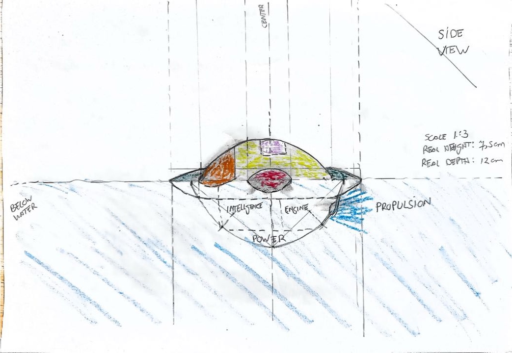
Central unit
This part is responsible for the overall command structure; for receiving and providing information to the different subsystems.
Visuals/ mockups
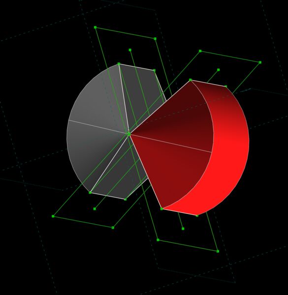
Must stuff I can visualize myself but my biggest concern at the moment is the propulsion. I would like to use some type of jet engine (the ones that create forward motion based on pumping water; so no propellor). I think this would be fast and safe. So before I start creating a newer version of my 2D/ 3D sketch I asked for inspiration from GenAI. Short summary it also came up with a waterjet propulsion idea. For now I will assume I can create this.
GenAI also mentioned the term holonomic robot In short if I could accomplish this UWO would be able to "move in any direction from any orientation, creating an incredibly mobile robot. So, it's easy to move the robot in a congested area".
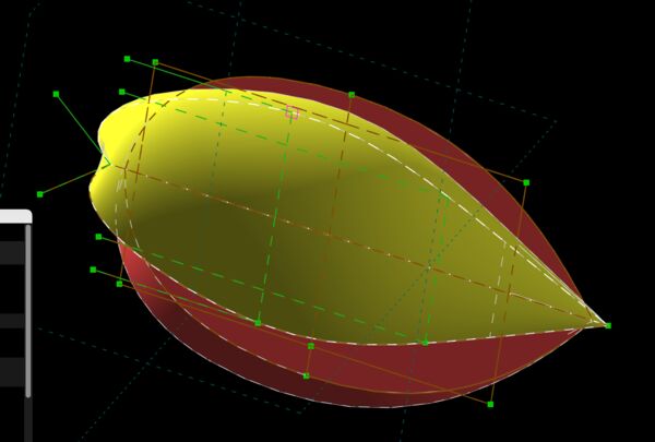
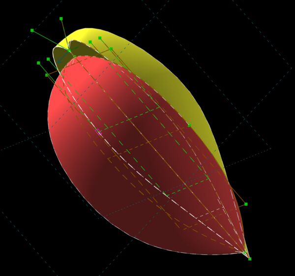
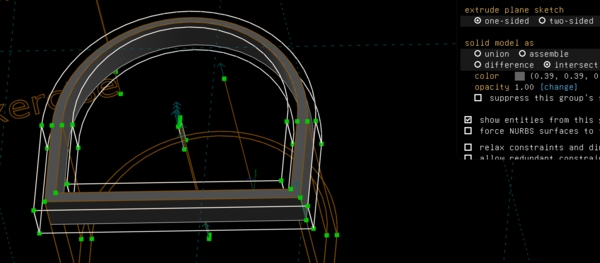
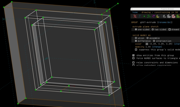
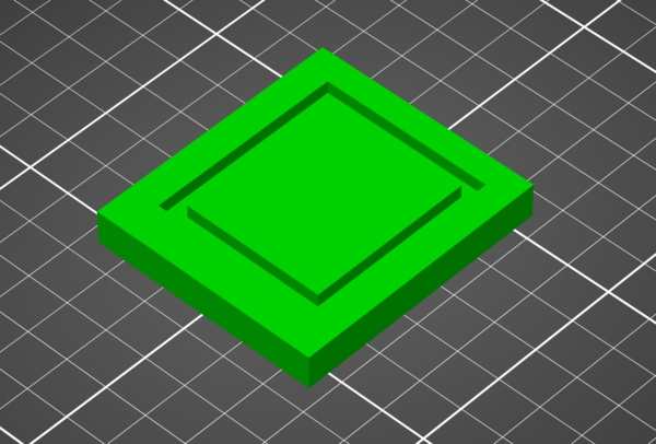
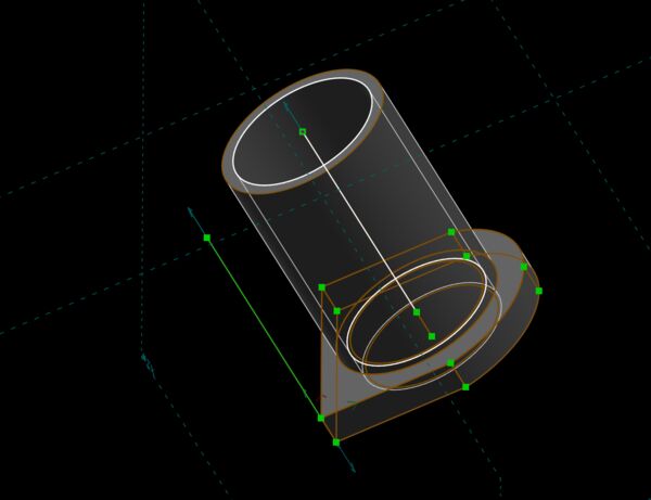
First 3D model in Solvespace
See week 2 for a description of the process. Just again the result for now.
Week 03
During our local session on Thursday, Henk suggested to discuss our final projects with Bas Pijls; just as an independent person. Regarding my idea he had some thoughts/ tips:
- Student Mkhitar (2025) made a submarine; look into that
- Water pressure from a "peralstaltic movement" is not fast enough
- By the pump; it is very tricky to make yourself
- Water tight is possible using epoxy.
- Maybe I can create my model from "piepschuim" and cut out what I want (I will learn this during CNC week), then put epoxy in it and suc it vacuum (sounds nice
 )
) - Overall do-able but choose what you make yourself
Week 09
So it has been a while since I've updated this page but assignments took over . Anyway this week I again thought about my final project. I think that RoboQuack 3000 is a more suitable name for it.
RoboQuack 3000 is an autonomous swimming fetch companion cleverly disguised as a classic yellow rubber duck.
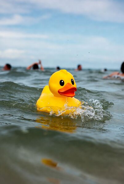
created with Grok Imagine using the prompt a cute yellow rubber duck floating in open water, actively trying to catch swimming people, dynamic action scene, realistic water splashes, duck with determined expression pursuing swimmers
At first glance it looks like an innocent bath toy, but inside it hides custom-designed electronics, AI vision, navigation, powerfull thrust engine and a couple distinct operating modes (also see week09):
- Game mode — it actively chases and tags swimmers with a cheerful quack
- Swim mode — it swims steadily in front, maintaining perfect distance to lead the road
- Stealth mode — it goes quiet and observes wildlife/ takes photos without disturbing the scene
Week 10
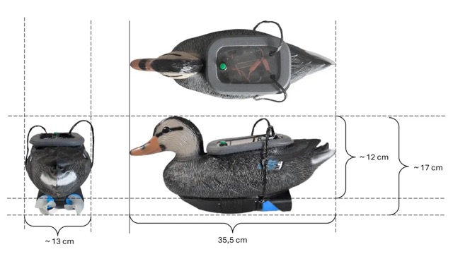
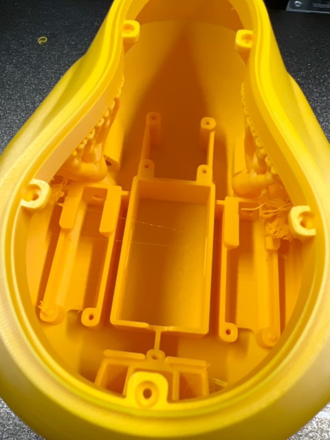
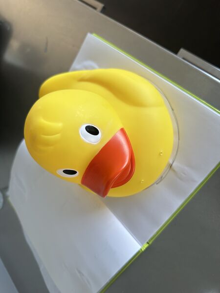
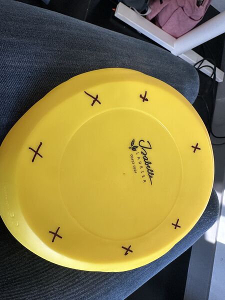
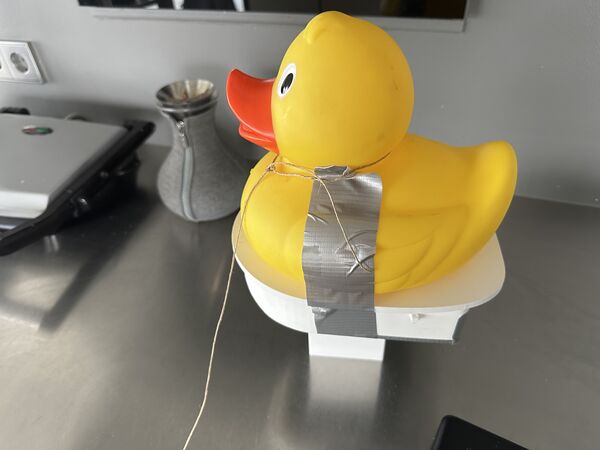
I decided to use the current duck I have. It's no too big, it's nice looking, it's already there. So now I only have to attach a motor in it, give it eyes and some kind of GPS sensor to know where it is.
I therefore took time to 3D scan the duck for the single purpose of using it later on in 3D programs like Blender or FreeCad or whatever. Why? Because I can then take it's measurements and use it to attach a floating platform on the outside and a plaform inside the duck to hold electronics; etc. It's nice for me to do that with a real duck in front of me.
Anyway please see [Scanning RoboDuck]](../finalproject/scanning_roboquack3000.md). And yes I changed it's name again to RoboDuck 3000 (a name says it all).
Week 11
So at the end of global class yesterday (1st of April) Neil mentioned again that midterm review is coming up and I should have finalised my plan by then. Also make sure to explain choices; they should answer a question. Specifically important are:
- system diagram
- tasks to complete
- schedule
I'll therefore use this page as a diary and keep track of questions/thoughts and decisions and use sub pages for more in depth detail (like system diagram, tasks, design, bill of material, etc). I already started with this last week but now I'm sure that's the way I want to go forward.
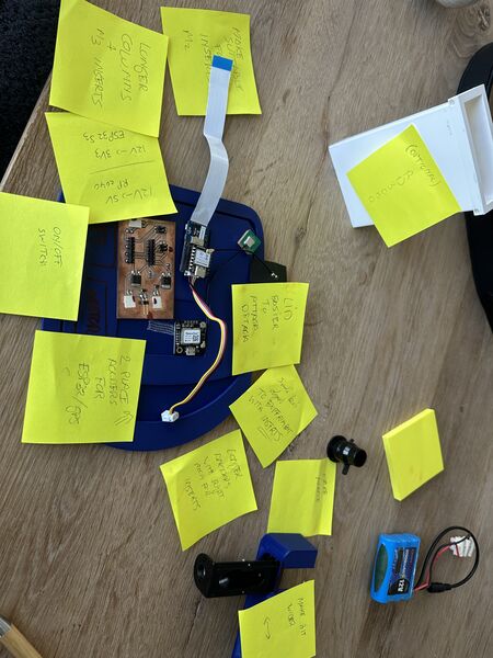
Thoughts/questions
- Based on
input devicesweek and this week were I could try the Grove Vision AI v2 module, I still think that detecting heads/faces is able using an AI sensor. What's going to be a challenge is that it's also able to detect upon a range of 10 meters and under shaking circumstances. - How to prevent the duck from flipping over in water with waves and wind? It is very light.
- How to attach the water jet engine to the duck?
- How to control the device in early stages; like having a remote kill switch? If it goes off into the distance then I should be able to stop it remotely. Maybe I should just make it completely remotely?
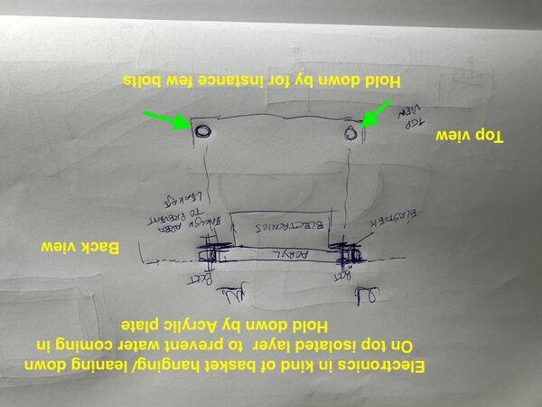
- What about water inside the duck? Were do I put the electronics?
Answers?
- Maybe I can train my own model on these objects? Using Sensecraft it's not that hard I think; doable. I can then train first with object A and extend that with more objects.
- I could make some kind of platform under the duck. I can then also use this platform to attach/ store the batteries. Maybe a catmaran design were the batteries are on both sides? I could attach the water jet in between and
juststick the duck on top of it.
image>?
- From Irja I got a link to chemicals to make 3D prints water tight. But I'm thinking of making the underwater hull during the molding and casting week; epoxy is water proof. So then the electronics could go in the duck it self. Probably as high as possible; maybe in the head? Also nice place to receive GPS signals and near the camera that I want to use.
image
- Regarding remote control ... maybe I should just make it completely remote control. That way I can keep the duck like it is as much as possible. But of course the remote control should then be water tight as well as it will be used near the water.
- Maybe a general switch on the duck (on/off)?
- Remote control means a way to communicate through air. So not only receiving but also sending (to let the remote controller know everything is ok). What kind of technique can I use for this? From the global class I learned that it depends on power, required functionality and distance.
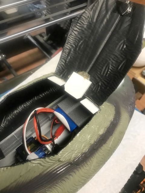
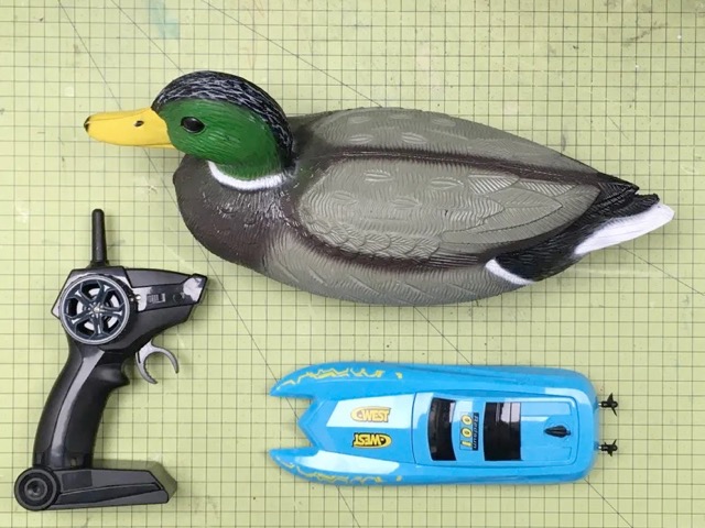
Trying out
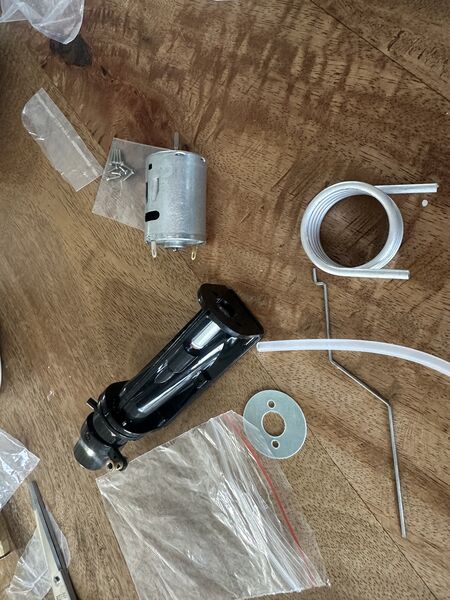
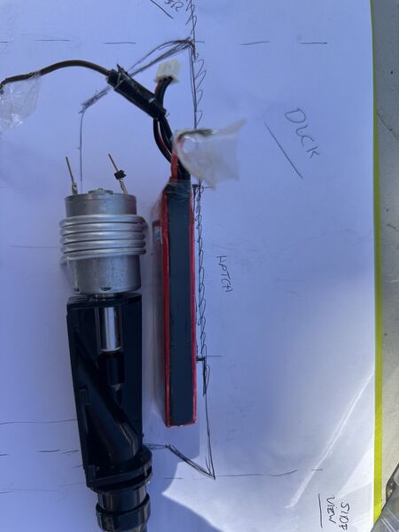
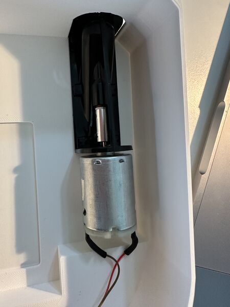
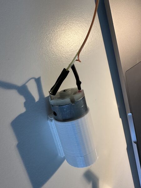
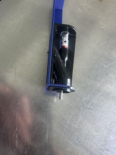
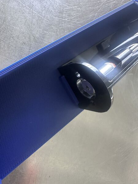
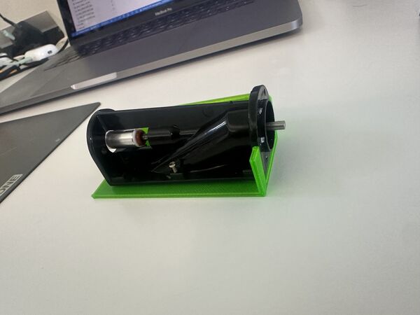
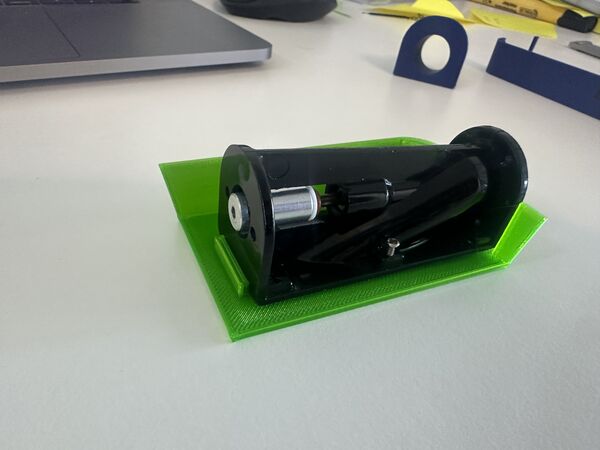
Received my water jet pump with motor
My idea was first to squeeze this pump into an already floating device ...
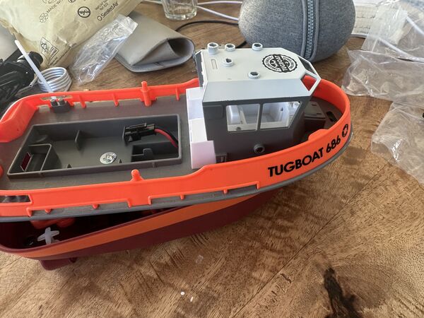
I ordered a cheap RC ship before
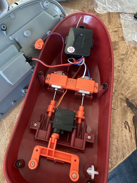
Get an idea how this works and how they keep it dry from the inside
... but the ships plastic was very hard and I'm not sure how to attach it; maybe first watch a video or something.
Week 12/13
Still in middle of machine week but I also want to work on some ideas for my RoboDuck 3000.
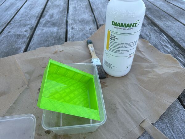
During my midterm review with Henk and Take (global evalator) Henk mentioned that floating would actually be the first priority; and that is true. Once a base platform with my duck on top floats I can add other things. I did also mention that I bought the product Dichtol based on the YouTube video to make any 3D print water resistance (that was a tip from Irja (one of the interns)). But it was their shared opinion hat the coming molding & casting week would be the answer to creating my platform because the base needs to be water resistance; Take also did a lot of experimenting with 3D and water and found it to be very difficult.
Inspiration from others
I mentioned that I'm especially fearfull for my 3D skills with FreeCad/ Blender. So I like to see if/how others made objects that float using molding/casting/3D printing. What kind of shapes and how did thy make it water tight?
I found a couple of websites that I found to be interesting ...
Radio Controlled Duck
source: RC controlled duck. Platform is 3D printed and requires a hole in the bottom of the duck (standard off the shelf)
also uses a waterjet
platform below is fixated permanently with kit
but this means that for access the top of the duck has to be opened up
Kit-bashing a duck
source: Kit-bashing a duck. Platform is taken from a off-the-shelf RC boat.
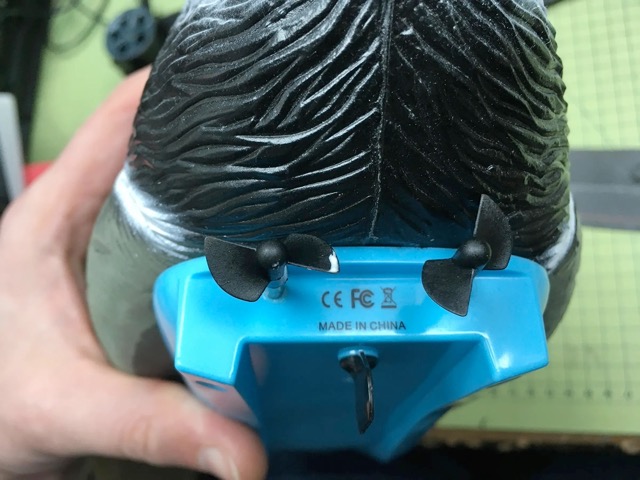
advantage is that the propellors stay outside; already taken care off
How to Build an RC Duck - With Arduino and Wi-Fi
something on top and on the bottom; wires run around the duck
use a mount plate which is fixated with kit on the bottom; so no cutting in the duck
hmmm there are underwater motors appearantly
looks cool but I think it will be difficult to balance it because of the weight on top of the duck
Rene the rubber duck boat with a nice video
completely 3D printed
designed internally for motors and electronics
video shows a white duck; good view from the outside; the duck's body is place on top of it
How I built the fastest RC Duck boat
An extension by the same maker to his radio controlled duck. He does this by using a waterjet propulsion. Good tip is to use velcro (klittenband) inside to attach parts so it can easily be removed/ attached again later on.
most important part is the platform under the duck that will hold the waterjet
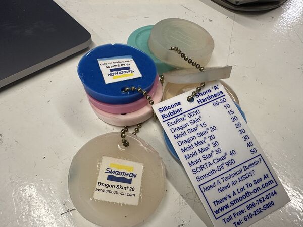
Molding and casting
There's a lot of info to take from this. But first I notice that this is mainly 3D printed. So why would I need molding/ casting? What is this anyway? So I looked up a video using a search phrase like what is molding and casting.
I watched about half of it and my take on this:
- molding is the process of creating a container or "negative" impression of an object
- casting is the process of filling a mold cavity/ container with a liquid material (for instance silicone, plaster, epoxy, or steel). The end result is the "positive" object again.
And yes I understand that I could use it to make a more water resistance platform on which the duck sits. I mean using silicon would even make it a bit soft so that when somebody hits the platform of the duck they are not hurt that much.
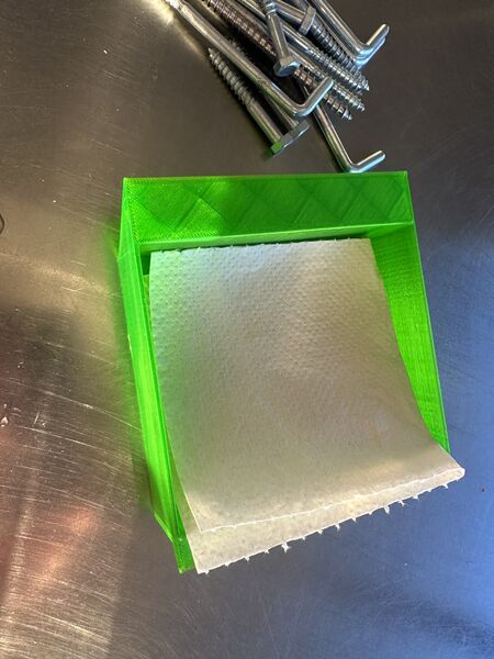
From my 3rd week I wrote down that the advise then was to make a mold from foam, use epoxy and then vacuum it. I don't know yet how that works and why that would be usefull but it sounds fun
So for now I'll assume that the platform will be created using molding/casting.
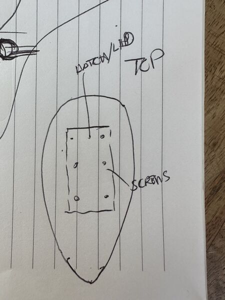
To access all the inner parts it would be wise to create a hedge on top of it that can be closed with some screws. To make sure no water comes in I can use a sealing.
Other parts
The camera/ gps sensor will be mounted on the outside of the duck as high as possible. One way I can do that is by making it really look like a Robo duck; for instance by putting on a helmet like RoboCop.


As I have a scan of the duck I could 3D print the helmet and paint it later on with a silver metallic spray. Behind the visor I could make sure the camera can see outside. The GPS sensor could be just under the top of the helmet!?
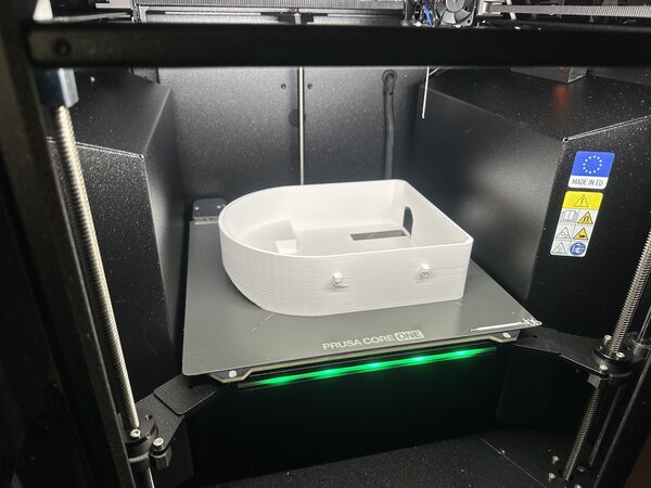
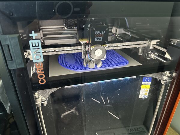
Week 14
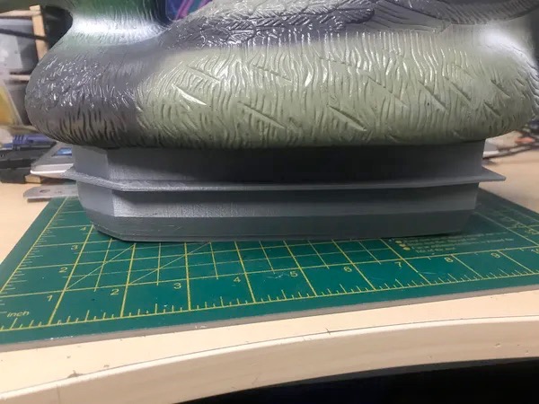
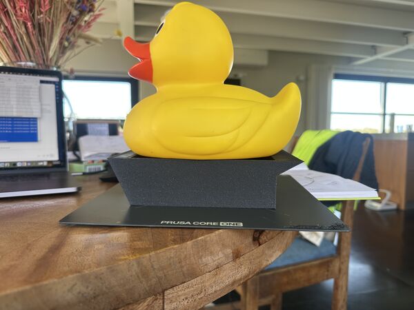
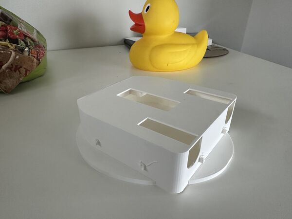
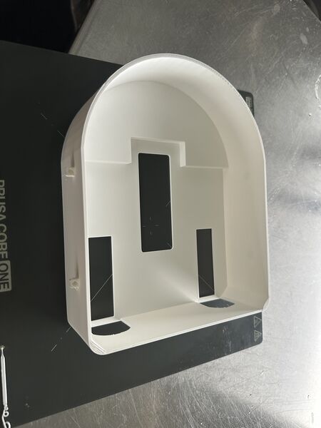
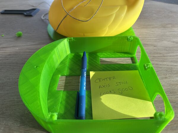
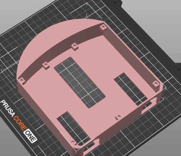
I used the Sunday to work mostly on my final project. As I promised myself I need to get something to float. As I bought a 3D printer I want to have an idea whether or not the duck will float when it's on top of a platform. So I decided to 3D print a first version of the platform.
Design process (again)
Here are pictures with explanation of the process.
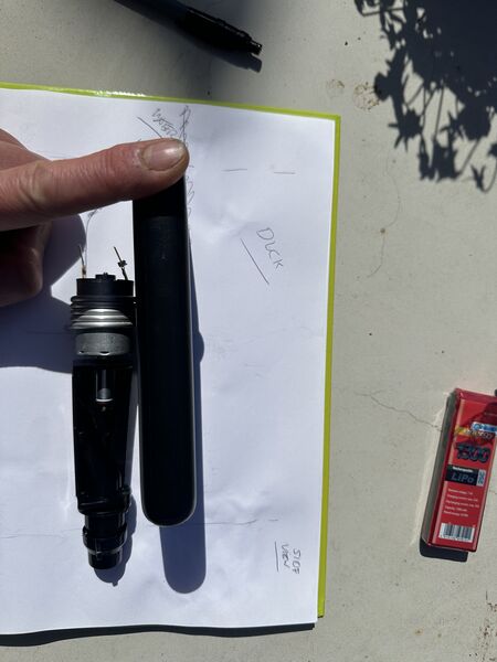
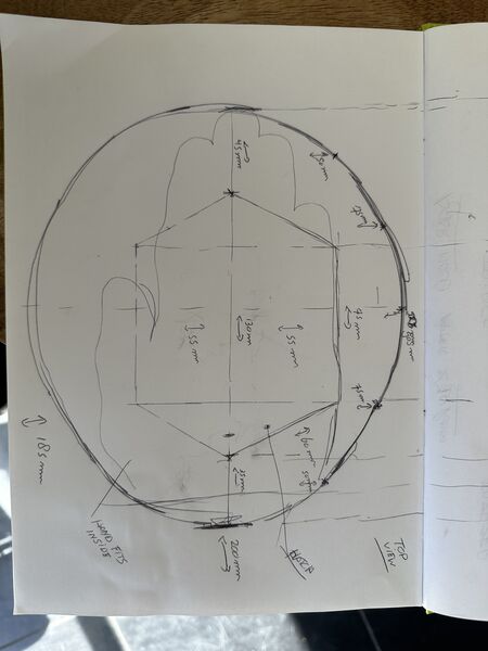
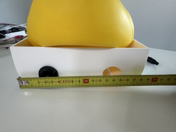
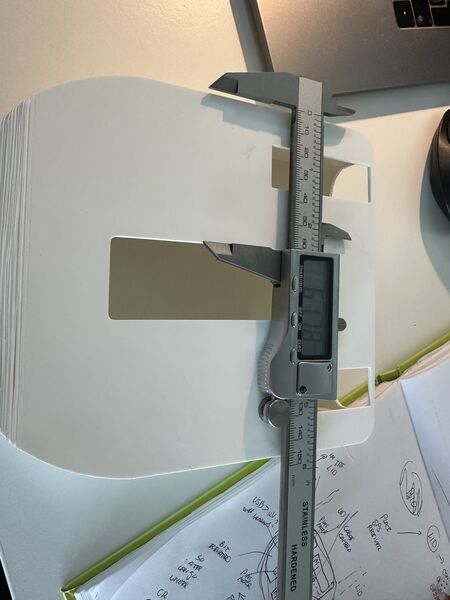
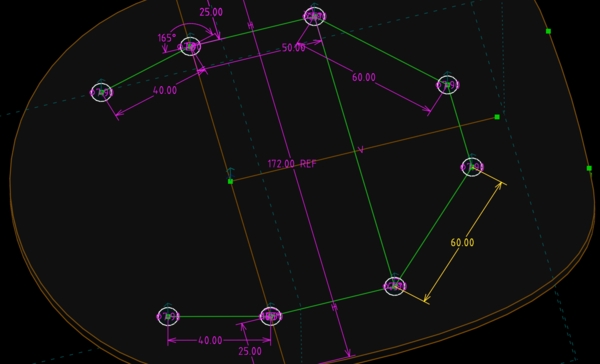
take the measurements of the duck
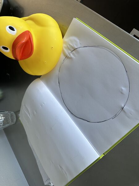
so I can draw on paper
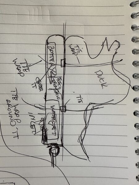
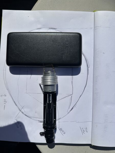
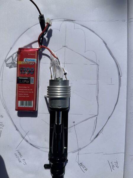
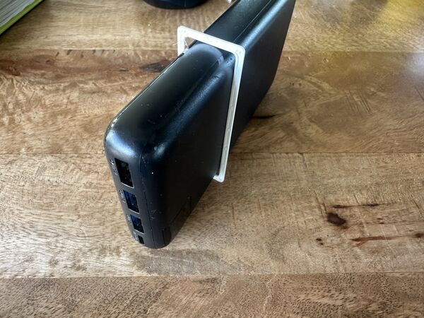
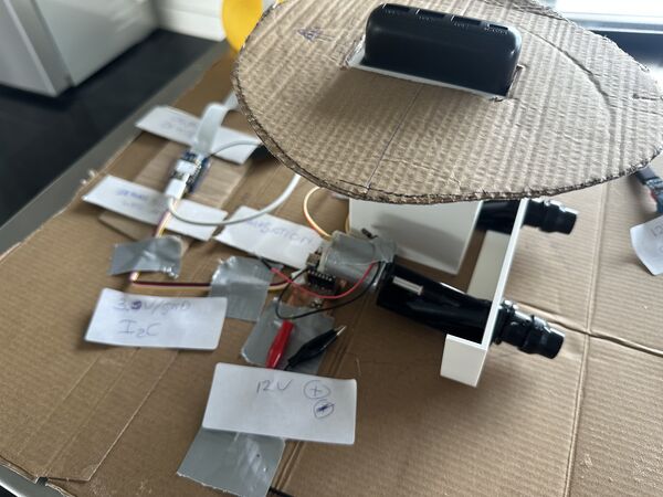
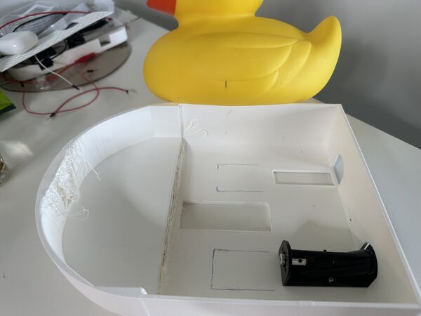
Then I started playing around with different layout's of possible components. Largely influenced by the power bank I want to use and the water propulsion system.
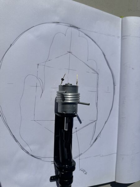
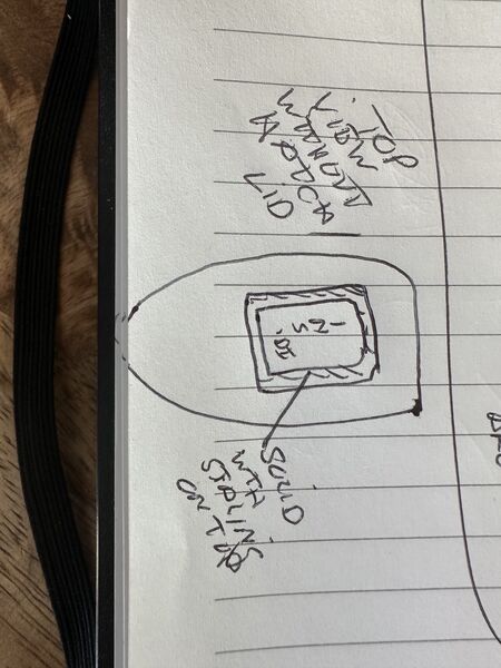
top level view
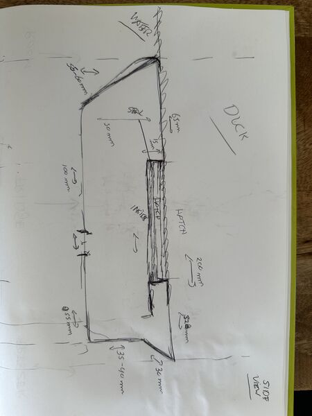
maybe the power bank can be under/ below?
but when looking from the side you can see I'll have problem to let water into the propulsion that way
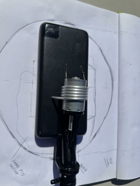
ok so maybe the other way around; power bank on top
or power bank rotated
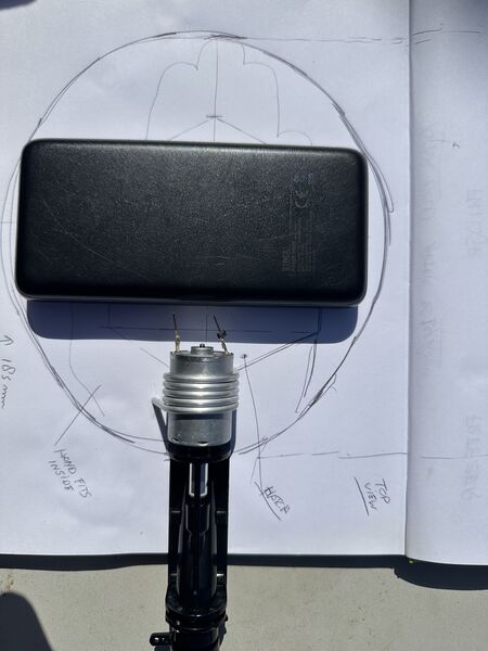
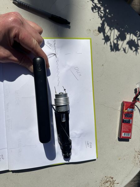
maybe I can make some kind of tail outside just for the propulsion
not very nice
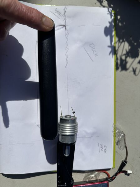
I have another one but that one delivers only 7.4volts
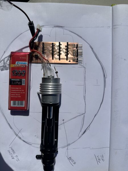
but maybe I can buy another version so just for simulation I also added a PCB to pretend it's the logic
battery on the side
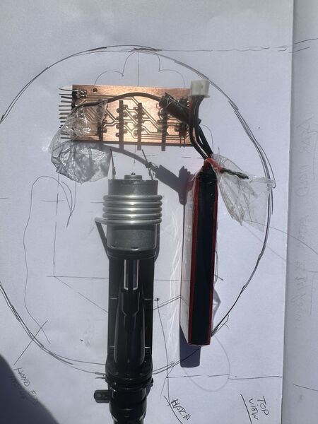
so from the side it could look like this
battery flat looking from the side; then I need less depth for the platform
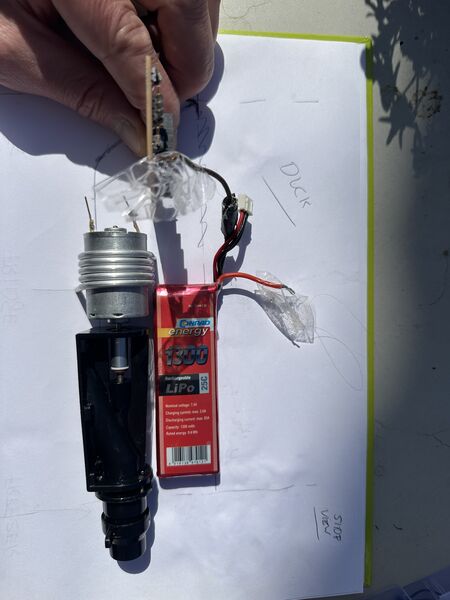
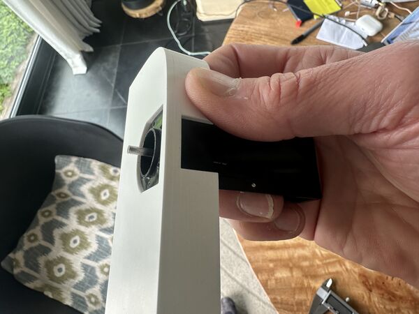
Oh and I need to be able to use my hand from the top to change batteries later on. Let's test if there's space.
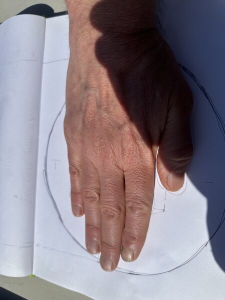
well I have big hands but it should be enough
Ok enough for now. I will try to find other batteries that provide 12V (for the motor; could also be 2x6V of course). Time to take some first measurements to desing it/ something in SolveSpace.
SolveSpace
I'm getting more familiar with SolveSpace. But I still found it time consuming. Here are some in between mistakes.
idea was to draw in 2D/ a plane and then revolve it around a line/ axis
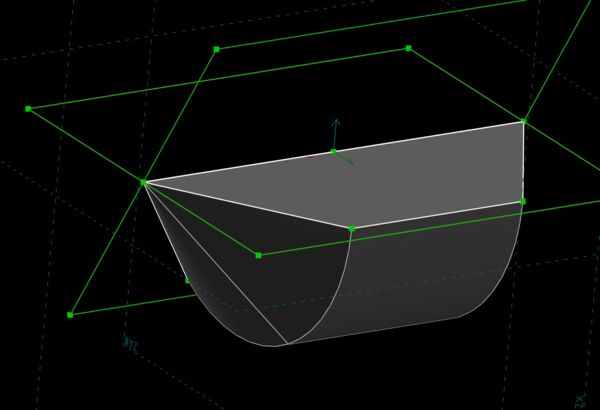
well yes and no
nice a basket ... but why
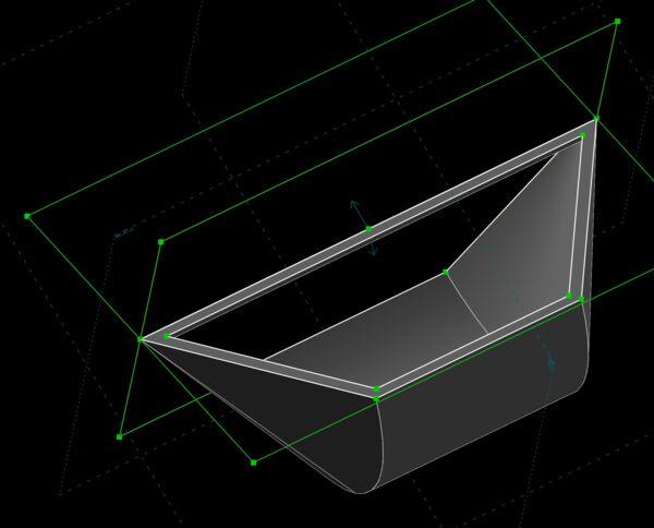
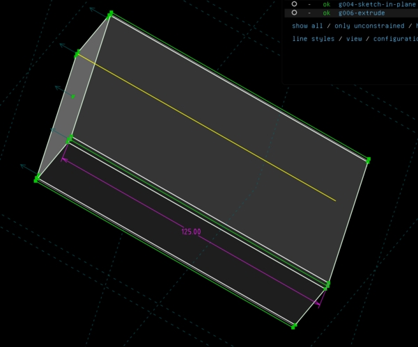
I found out that for revolving I should only draw part of the drawing. So half a rectangle or half an object instead of it's symmetry alread. So when I started doing that I got better results.
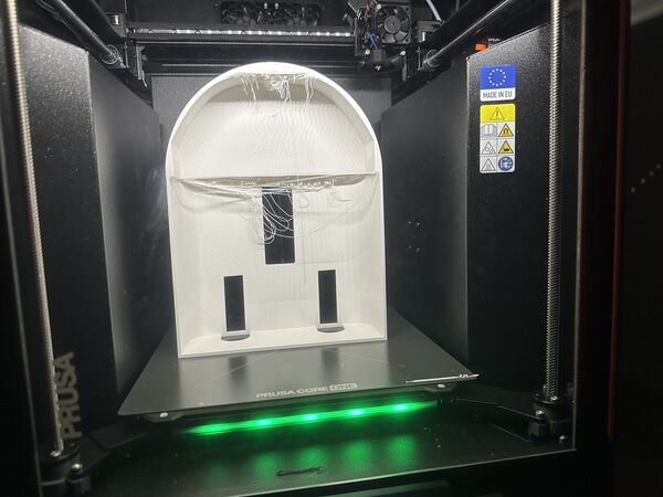
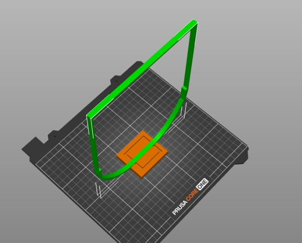
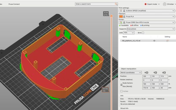
Well it's not the result I really want but spiral desing and will it float so let's just print this one.
after 2 hours and using a draft kind of setting this came out; nice
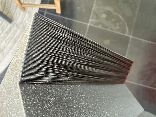
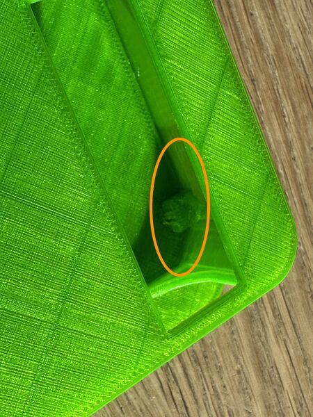
Oh but the back/ wing has overhang ... hmmm have to find a solution for that
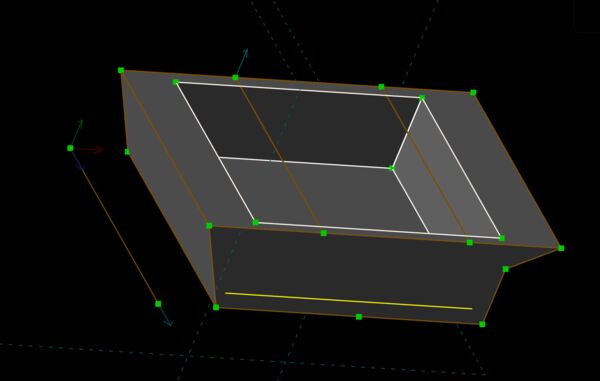
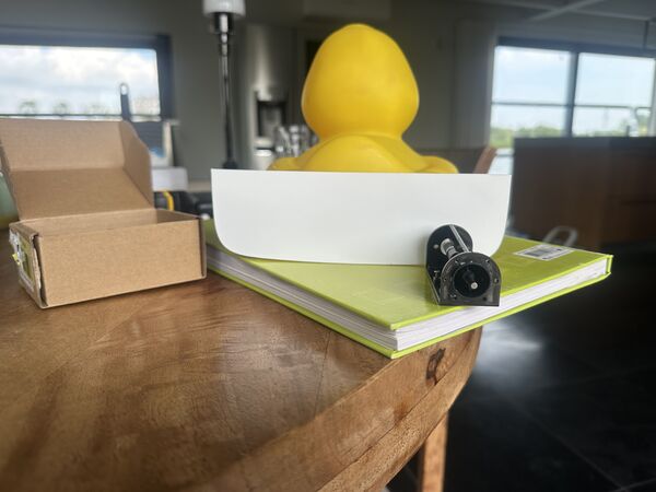
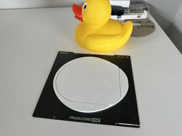
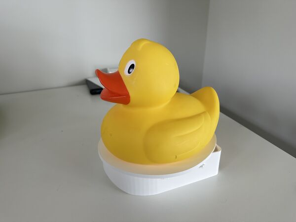
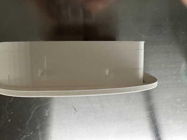
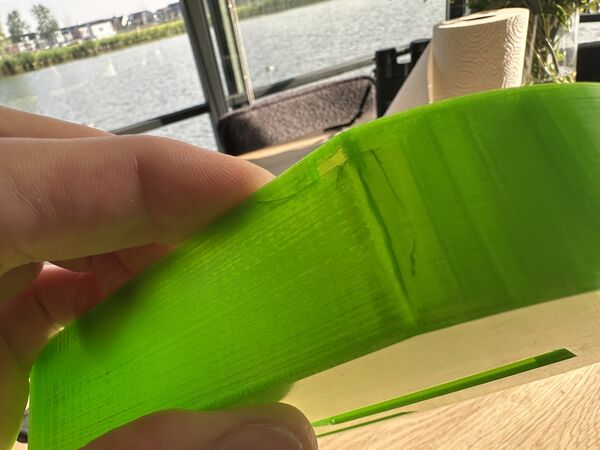
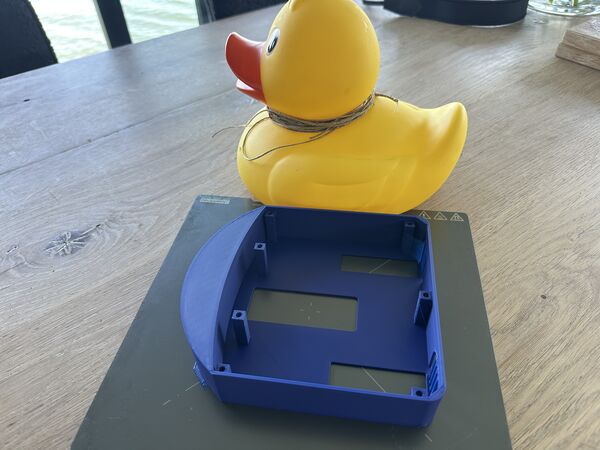
But will it float ...
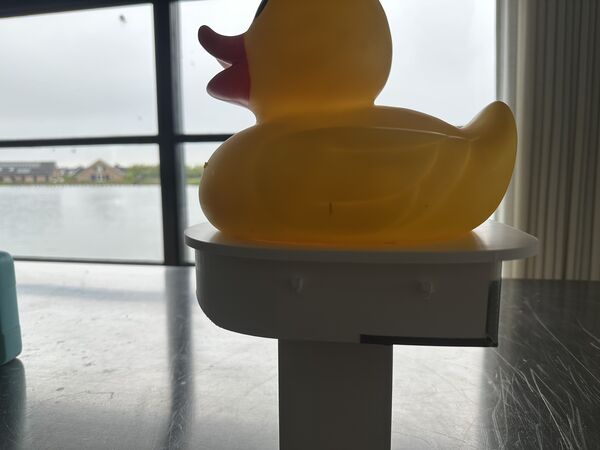
yes it does
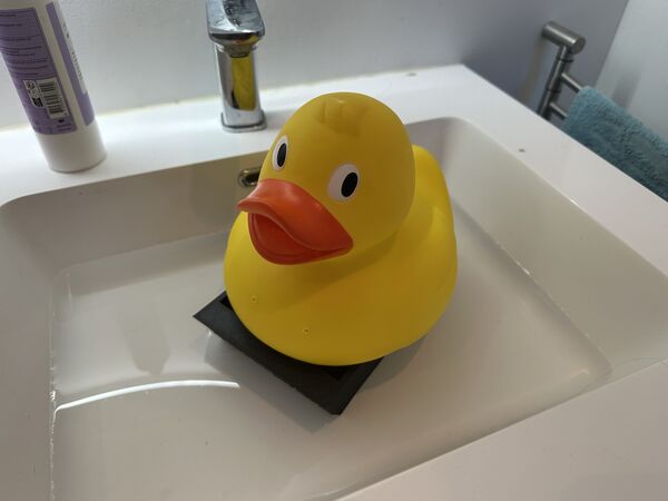
and with some maneuvring even the duck will sit on top of it
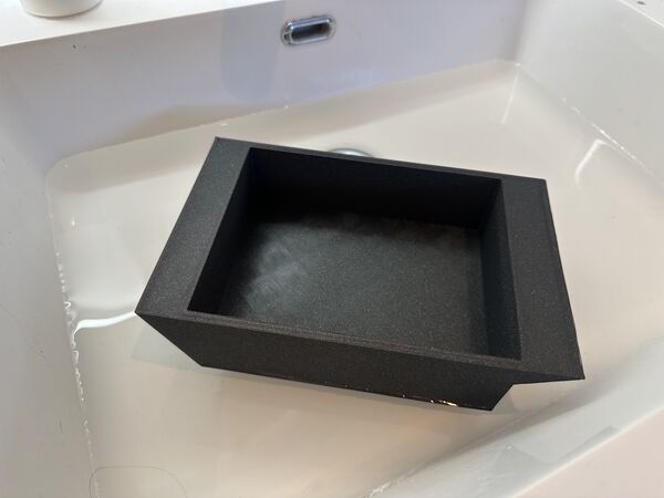
Ok well yes I have somethig that floats but I found that:
- needs to be deeper or needs side baland aotherwise duck wil flipover / wings
- and place hodler for the duck/ so it stays in place
how about the weight it can take and does water come in? Well this looks ok.
What about weight that might actually be used
just some elements with a heavy power bank
not sure if I'll use this power bank but for the test it's nice to assume
Well it floats and water is NOT coming in
Design proces (again)
nossle how it should be attached at the back
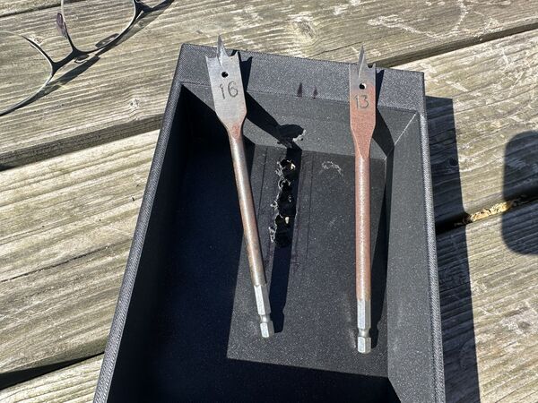
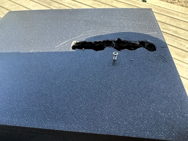
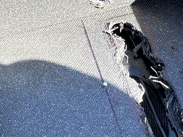
just use drilling tools to make the hole; will fix later in 3D design
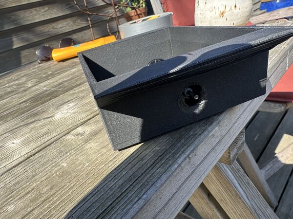
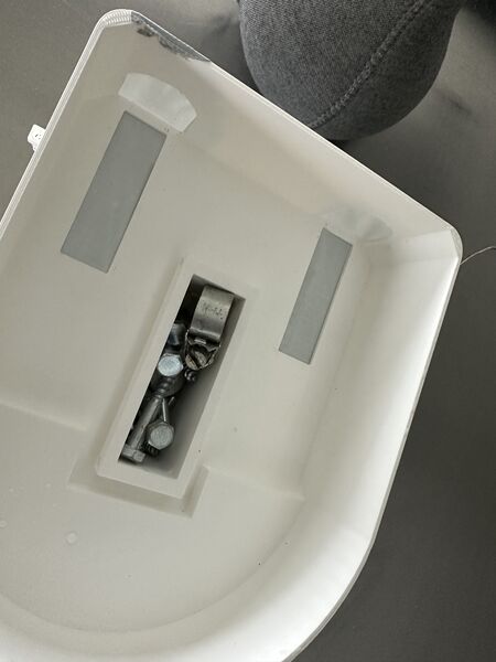
result sofar
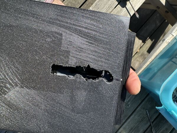
used a drill to make a water inlet
this is how it should be fixated
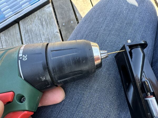
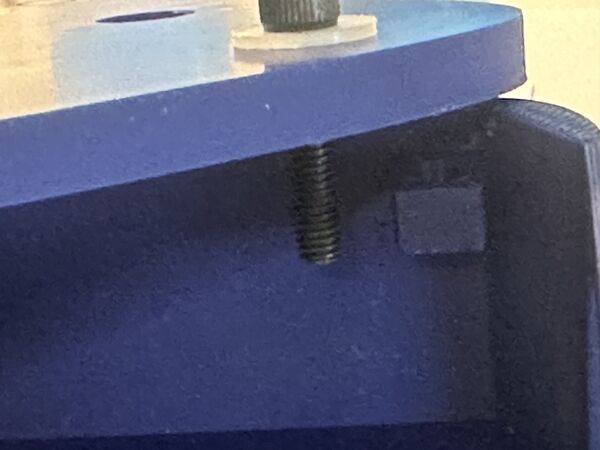
bought a small 1mm drill use the bolts that came with the waterjet
idea is that I use those to put the water jet in place
but found that there were not long enough to also go through the 5mm bottom.
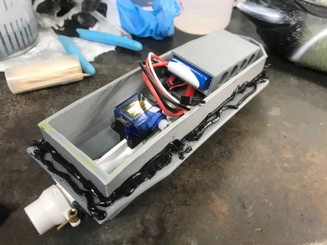
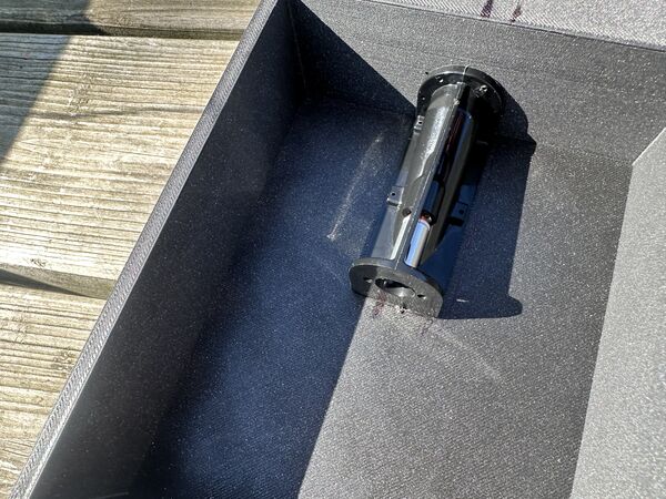
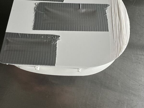
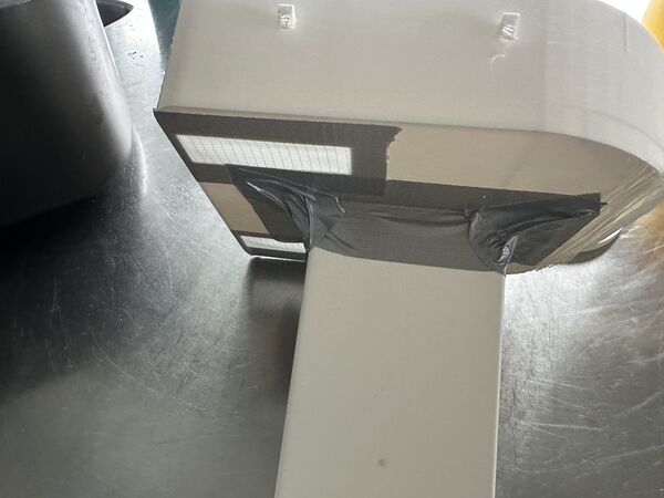
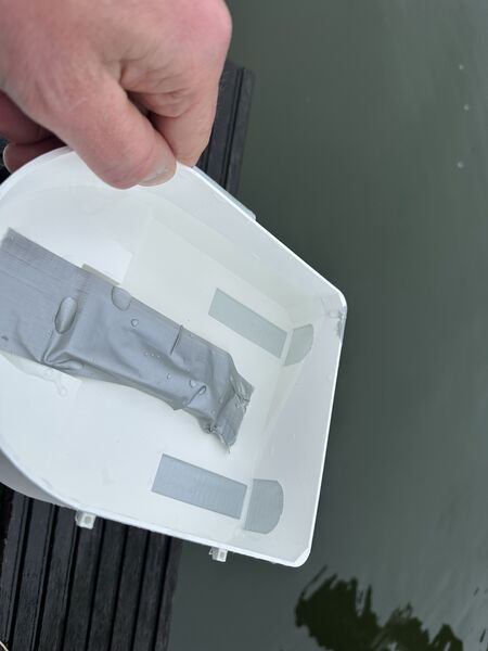
I ended up using duck tape to fixate the motor and to keep the water out. I used an older battery I had (7.4v 1300mAh) to power the motor for now and just turned it on and see what it would do.
it floats, it has some thrust despite the nossle not being attached
Learned/ decided/ questions:
- the 3D printed platform does not let any water through despite being printed with DRAFT like settings.
- the 3d printed platform is light; what if I change that for epoxy; won't it become to heavy?
- I'm definitively NOT opening up the rubber duck. It would have to make some kind of mechanisme to close it of and attach it to the platform etc... This would only create more problems. So I'll stick to the
helmetidea - to enable thrust the platform is to be below water. So it must be made heavier. A power bank will do that I think. BUT I should lower the point of gravity to make it more stable (like a sailing boat)
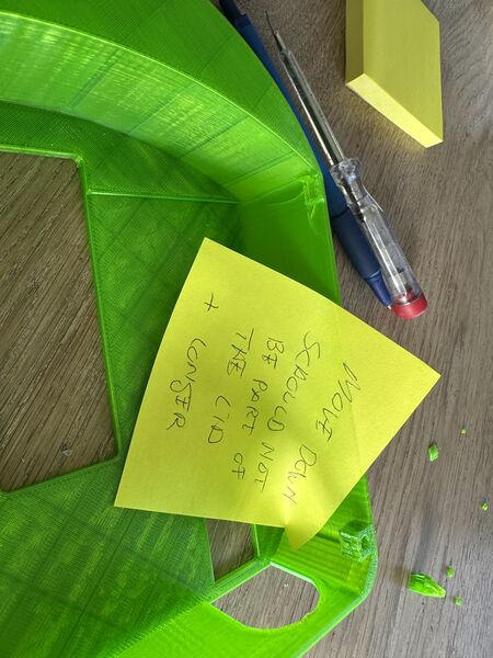
- It also means that the
servicehole (the one I need to get into the hull) needs to really be water proof. This I could solve making some kind of hatch that has silicone/ flexible rubber as an inlay and use screws to close it - The bottom can be a bit thinner I think; now it's 5mm; my guess is that 3mm is enough
Week 14
At the start of the week Henk/ Remco gave me nice input.
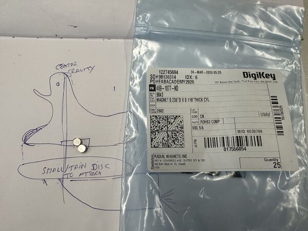
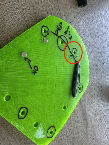
How to fix the Duck onto the platform? Well use magnets
- Epoxy is indeed much heavier than printed plastic. So idea to continue with 3D printed hull is ok for now
- Why not move the GPS sensor in the hull? Does not need to be on top; in a building you can receive the signal as well; so will do fine in the hull. This also means that the electronic parts for this can move into the hull
- Helmet with electronics; why not use a longer cable and different camera? Then electronics for this can also move to the hull. Henk send me two links: https://nl.aliexpress.com/item/1005009339247009.html and https://nl.aliexpress.com/item/32820946214.html
Remco suggested to make goggles and put the camera in there. I like it. I could CNC a mold and use Dragon skin type of material as casting material. Same material Remco used for last week's assignment.
Week 15
Ok 3 weeks to go; it's going to be fun.
During the week's assignment I tested the range of the connection between my laptop and the ESP32C6 via BLE. I ended up with a ESP32S3 that runs a Wifi access point that is connected to the Grove AI module. Wifi gives me a two way communication and enough range. I also built a small UI to talk to the the ESP32S3 using web sockets. The content for the UI is sent by the ESP32S3; it consists of Javascript with p5.js library and html.
Training AI model
I also found this article. It explains another way to create a model from scratch and convert it so it can be uploaded via SenseCraft.
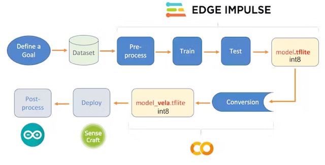
using Edge Impulse; a leading development platform for machine learning on edge devices
It's good to know for now.
Working on the hull
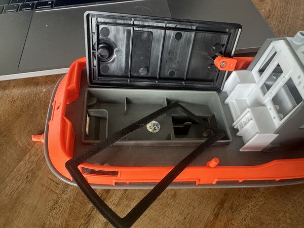
Ripped apart this RC boat to see how they sealed the top
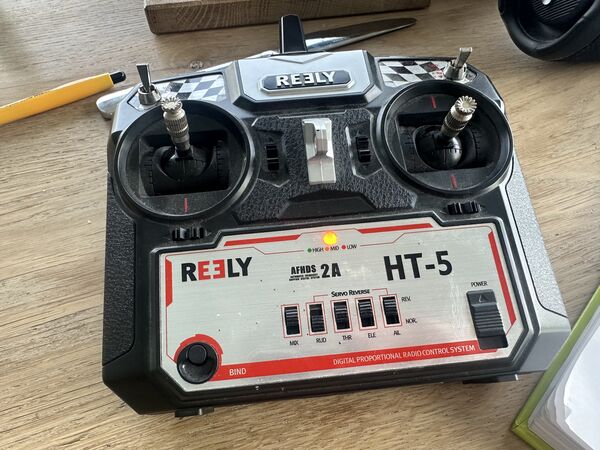
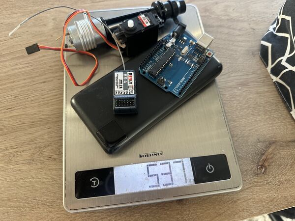
Old remote control from 10 years ago
to my surprise I got it working again with the receiver; even with the micro server I intend to use
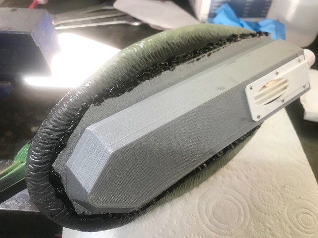
Working on the hull prototype
My idea is to first complete the prototype of the hull and use this to try out everything. But for this I need to put it also into the water.
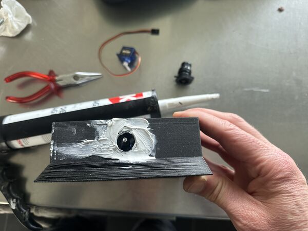
Used silicone kit to add the nozzle at the outside
I measured the thickness of the steering rod that the servo will use to move the angle of the nozzle. It will run through a small tube that I ordered online.
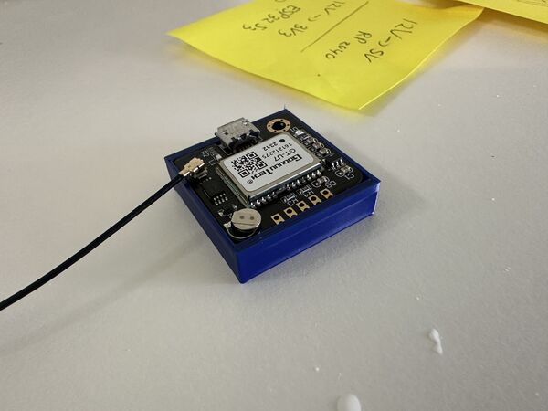
Navigation
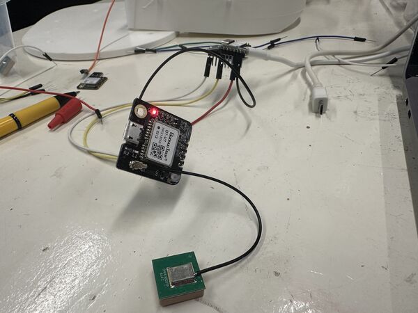
Time to unbox the GPS module from SeeedStudio that's based on the GPS Air530Z. I bought it a while ago because of the benefits for my outside project.
It supports GPS / Beidou / Glonass / Galileo / QZSS / SBAS, which makes it suitable for GNSS positioning applications such as car navigation, smart wear, and drone. Meanwhile, this module is capable of receiving more than 6 satellites at the same time and is able to work excellently even if there's a very bad signal. Low power consumption at only 31uA
It has a nice manual which is in Chinese The wiki tells me more.
The basic code they provide
#include <SoftwareSerial.h>
SoftwareSerial SoftSerial(2, 3);
unsigned char buffer[64];                   // buffer array for data receive over serial port
int count=0;                                // counter for buffer array
void setup()
{
    SoftSerial.begin(9600);                 // the SoftSerial baud rate
    Serial.begin(9600);                     // the Serial port of Arduino baud rate.
}

void loop()
{
    if (SoftSerial.available())                     // if date is coming from software serial port ==> data is coming from SoftSerial shield
    {
        while(SoftSerial.available())               // reading data into char array
        {
            buffer[count++]=SoftSerial.read();      // writing data into array
            if(count == 64)break;
        }
        Serial.write(buffer,count);                 // if no data transmission ends, write buffer to hardware serial port
        clearBufferArray();                         // call clearBufferArray function to clear the stored data from the array
        count = 0;                                  // set counter of while loop to zero
    }
    if (Serial.available())                 // if data is available on hardware serial port ==> data is coming from PC or notebook
    SoftSerial.write(Serial.read());        // write it to the SoftSerial shield
}


void clearBufferArray()                     // function to clear buffer array
{
    for (int i=0; i<count;i++)
    {
        buffer[i]=NULL;
    }                      // clear all index of array with command NULL
}
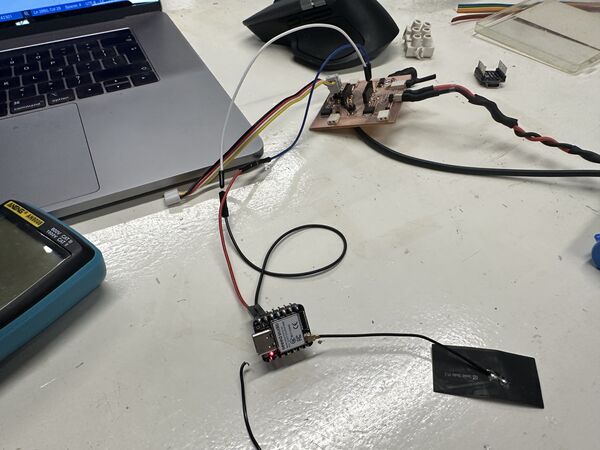
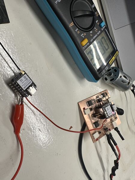
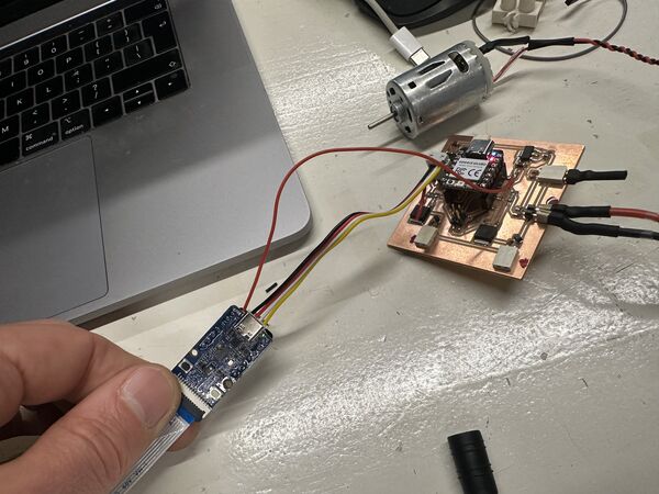
So I tried this out with a basic setup using an older PCB I made
After turning it on
Knows where it is
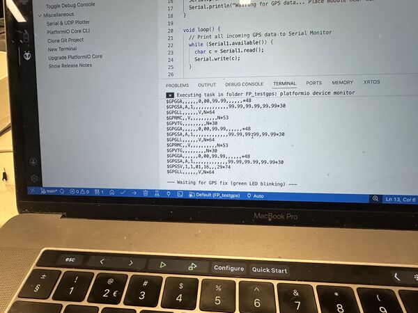
Ok then switching wire, uploading code I got a lot rubbish ... maybe to fast? I adjusted the speed to 9600 and then it worked fine.
I looked for info on the info coming out of this sensor. Via this article I was directed to an English translation of the Chinese manual. From this I get that I can send commands to it. But also that a lot of people are using this and that there are libraries.
Below is piece of the output that goes on and on
$GPTXT,01,01,01,ANTENNA OK*35
$GNGGA,164442.000,5218.96475,N,00503.42767,E,1,19,0.7,3.9,M,43.0,M,,*40
$GNGLL,5218.96475,N,00503.42767,E,164442.000,A,A*47
$GNGSA,A,3,01,03,04,06,09,17,19,28,31,,,,1.4,0.7,1.2,1*3F
$GNGSA,A,3,07,10,11,12,19,20,23,29,32,35,,,1.4,0.7,1.2,4*37
$GPGSV,3,1,12,01,31,139,36,02,,,15,03,62,075,41,04,66,174,29,0*52
$GPGSV,3,2,12,06,40,304,37,09,37,209,34,12,,,26,17,33,234,37,0*57
$GPGSV,3,3,12,19,39,271,37,25,,,25,28,18,040,30,31,28,068,33,0*56
$BDGSV,3,1,12,07,25,045,32,10,26,056,20,11,25,173,30,12,82,225,32,0*7D
$BDGSV,3,2,12,19,52,239,27,20,76,066,39,23,11,051,20,25,,,13,0*4F
$BDGSV,3,3,12,29,41,192,38,30,,,14,32,18,062,22,35,50,281,36,0*4F
$GNRMC,164442.000,A,5218.96475,N,00503.42767,E,0.00,102.38,040526,,
Appearantly the output is in the NMEA format.
NMEA is an acronym for the National Marine Electronics Association. NMEA existed well before GPS was invented. The purpose of NMEA is to give equipment users the ability to mix and match hardware and software. NMEA-formatted GPS data also makes life easier for software developers to write software for a wide variety of GPS receivers instead of having to write a custom interface for each GPS receiver. There are different NMEA sentence type, and the type is indicated by the first characters before the comma
Ok, this is rabit hole, so it would be helpful to use a libary. As Arduino itself does not provide one (I've looked but nothing with GPS Air etc..) I found an option. Looking at the header file and the example code the author provides a way to send commands to the sensor to only get what you want.
My plan is to keep it simple for now, just pick out the lines that are related to my regional area and later on send commands if needed. But what info is for my region?
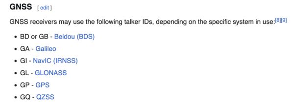
According to Wikipedia it starts with a Talker ID followed by a sentence.
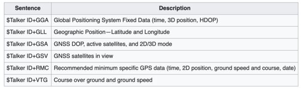
So when I want to use GPS information and want to know were I am and how fast I'm going than RMC is my guy/ girl.
Example: $GPRMC,092750.000,A,5321.6802,N,00630.3372,W,0.02,31.66,280511,,,A*43 Means: UTC Time 09:27:50, location 53°21.6802′N 6°30.3372′W. Speed over ground 0.02 knots, course over ground 31.66°. Date is 28 May 2011.
Without a big library I should be able to read lines from the output and then split that string into these parts.
Looking at the output I don't see GPSRMC but I do see GNRMC. This indicates appearantly that the data comes from a combination of multiple satellite navigation systems, not just one; GN = GNSS (Global Navigation Satellite System).
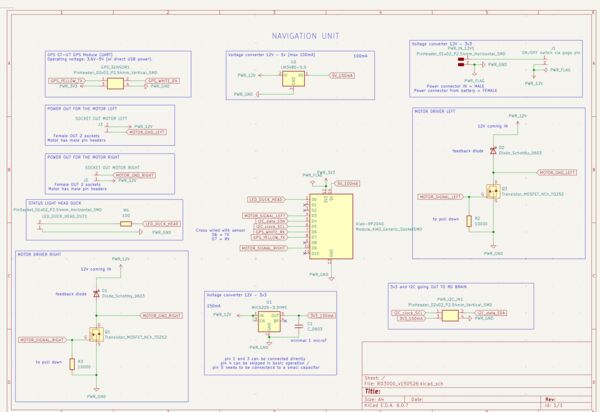
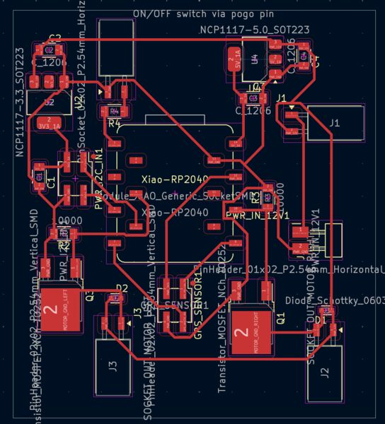
I then worked on a basic setup of the code which let me think about the PCB design.
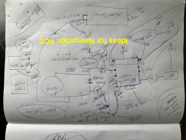
PCB
So the Navigation module will take care of managing the motor, the micro server while getting input from a GPS sensor. On top of that it takes commands from the central unit via I2C; also to communicate back. Based on that idea I extended a design I made a time ago.
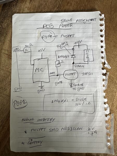
page number refers to Practical Electronics for inventors
something old and something new
Is everything ok enough to switch to Kicad?
-
During the group assignment we worked with I2C between PCB's so this should work here as well.
-
I tried the micro-servo before and remembered that Kris (from Finland) suggested to add a capacitor. Because they can create big, sudden current spikes when they move for a fraction of a second. This can lead to: jitter or even the MC resetting because of the power drainage.
Looking at AdaFruit
You can usually cure it by adding a high value capacitor (470uF or greater) between GND and 5V on the breadboard. The capacitor acts as a reservoir of electricity for the motor to use, so that when it starts, it takes charge from the capacitor as well as the Arduino supply. The longer lead of the capacitor is the positive lead and this should be connected to 5V. The negative lead is also often marked with a '-' symbol.
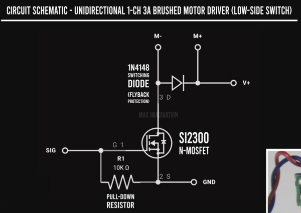
- What about the Mosfet?
Well at home I used the book Practical Electronics for inventors to come up with this and according to this source I need to add a pull-down resistor between the GATE and SOURCE of the MOSFET.
Note
It gave me the idea to have an atonomous home function built-in. If the duck would loose it's connection during more than 5 minutes it would go home to a pre-programmed location.
Week 16
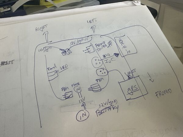
At home, I spend the last part of Wednesday drawing schematics and options of my logic/PCB's etc.
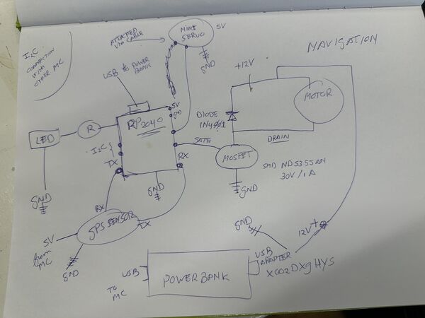
System design
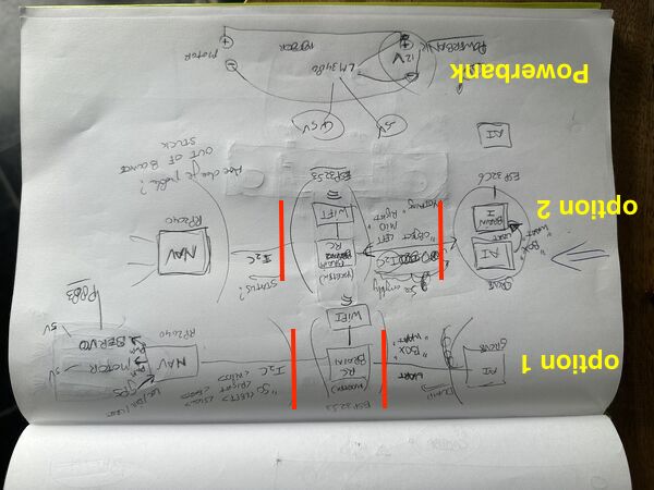
option 1 leaves AI interpreation to the brain and get info from AI via UART; in option 2 I moved object recognisition completely to seperate MC, now the brain talks via I2C to everybody
Navigation unit extended with new ideas
The brain will control everything and talk to the other units
Note
I'm aware that the RP2040 that will run the navigation unit is going to be busy. I was also concerned that it could not do these tasks in parallel (PWM on micro servo, PWM for the motor and reading UART). But a quick search on the internet linked me to a Github repo that enables me to use Hardware-based PWM channels on RP2040-based boards. Again a todo thingie.
Hull design v2
Based on input from the group I struggled with the idea of a tunnel and then attach the battery below that. I also worried more about the possible speed of the duck (meaning not at all ) and what's does it mean to be a RoboDuck then?
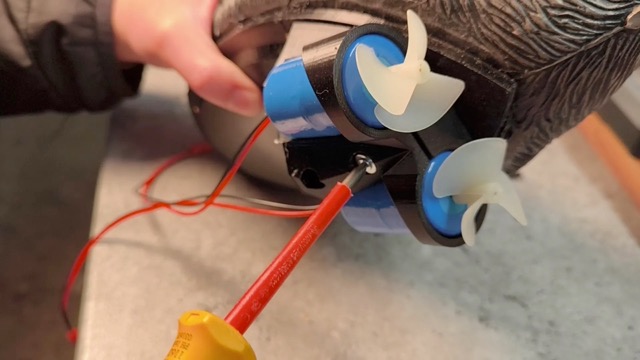
Long story short I did a bit of flip thinking. Why not use 2 jets.
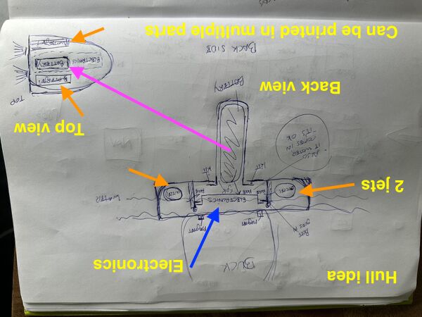
The hatch problem does not get worse or better but sure enough I can now lower the battery like the keel of a sailing boat for more stability. The 2 jets will at least mean more speed than 1.
Regarding steering ... Option: I don't need the micro servo's anymore. To steer I could just have more power on 1 jet and less power on the other. Other option: have a central rudder attached to the micro-servo.
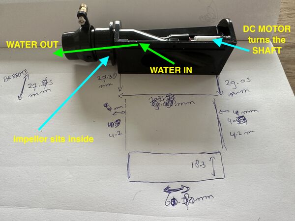
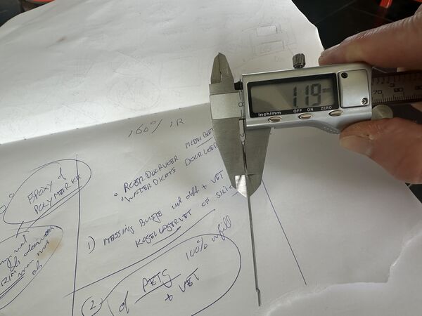
measuring one of the waterjet pumps
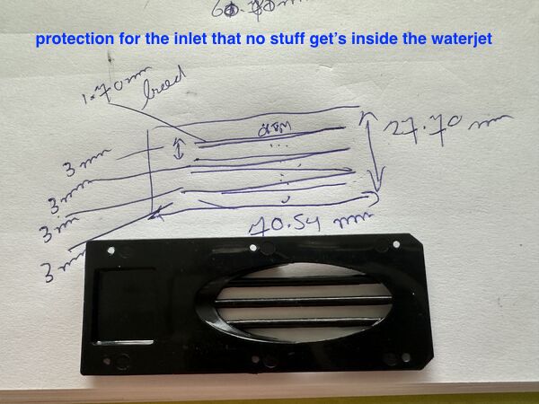
measuring the protection that is attached below the inlet
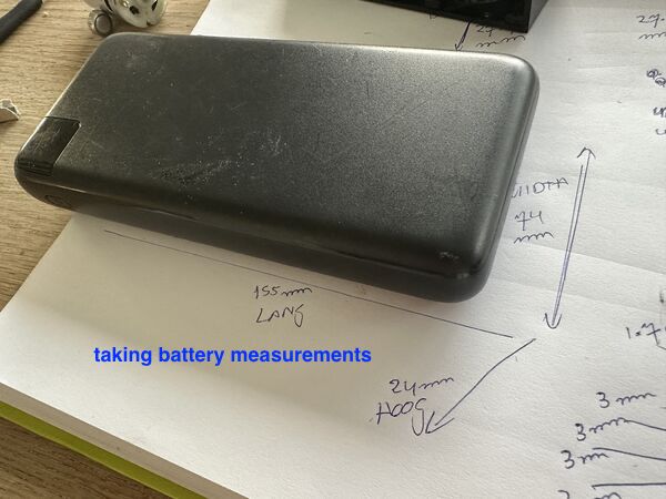
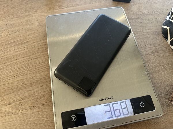
the power bank that's going to act as battery
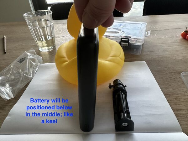
some kind of pocket needs to be created in which the battery goes vertical below the duck
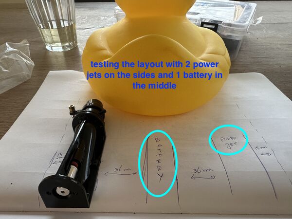
enough width for 2 power jets and 1 battery
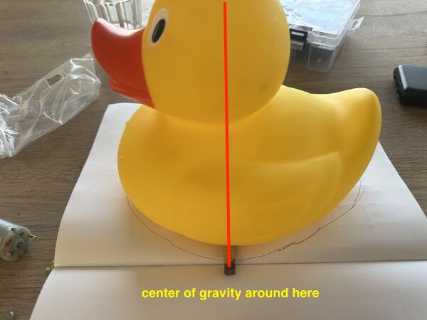
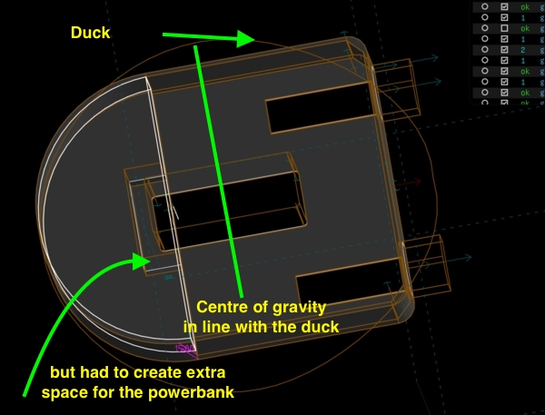
Idea is that the battery is positioned in such a way that both the center of gravity of the duck and the battery are around the same spot. Idea is that it will not lean forward or backward.
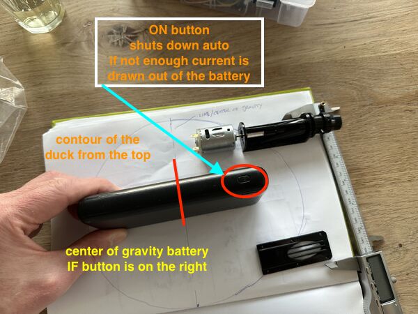
if the battery is positioned like this then we should be ok. But for space I need to somehow place the waterjets a bit outside at the back
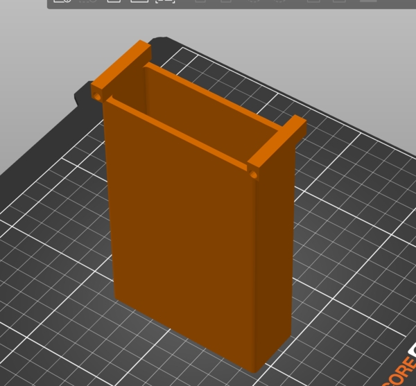
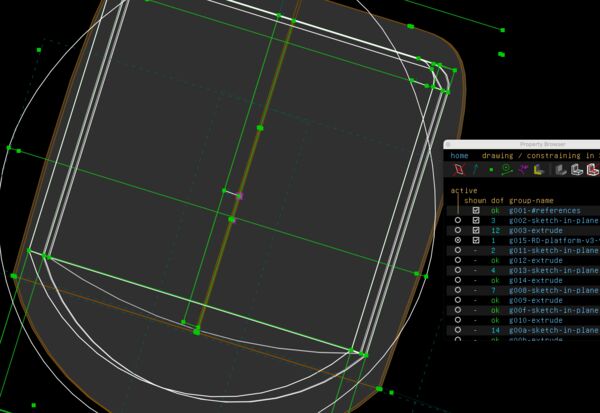
Visualize design hull v2
First I switched to the latest stable version of Solvespace; release 3.2 from March 2026. Good to know they are still enhancing the software.
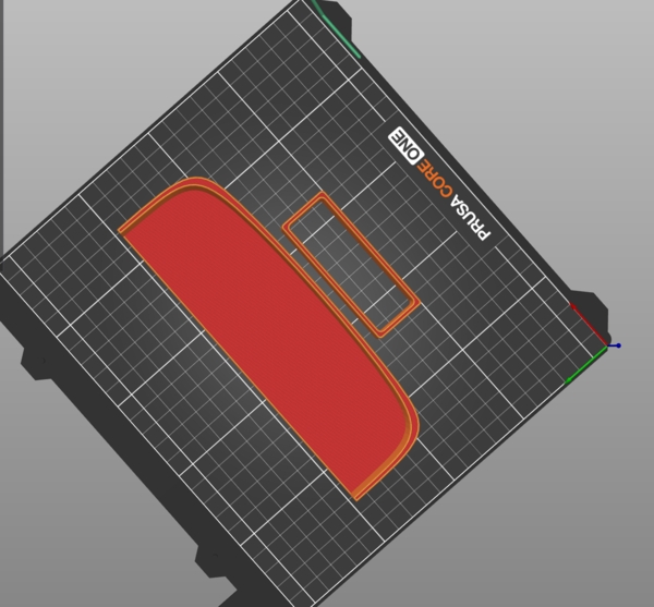
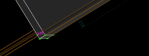
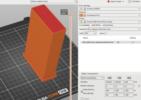
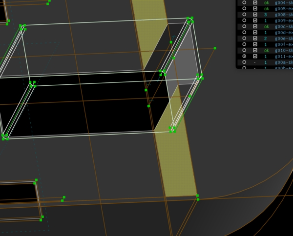
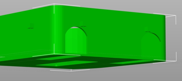
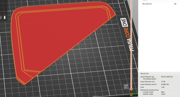
Before lunch I wanted to print the battery holder. Piece of cake. BUT NO :sad: .. I had a lot of trouble with the boolean operations.
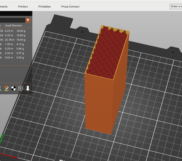
After exporting my 'hollow' design as STL (at least I thought it was) and importing it in PrusaSlicer it was in fact a brick
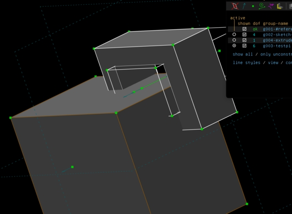
Some of my trials before creating the design of the battery holder. I found out that I have to start from the outside in.
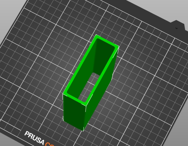
Then finally I got the ring in which the battery should fit. But as my daugter is learning for exams I can't print it right now. It looks good in Prusaslicer though.
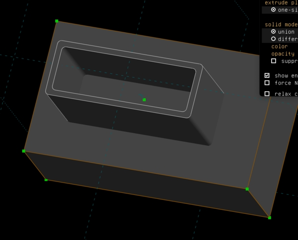
Then still a struggle to create a hole in the bottom of the platform ... Arghh
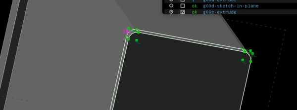
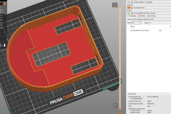
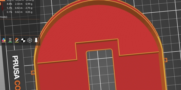
Later that day I just started again; this time with better results.
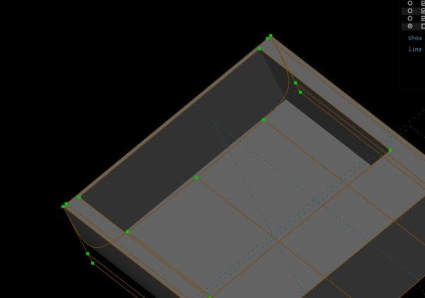
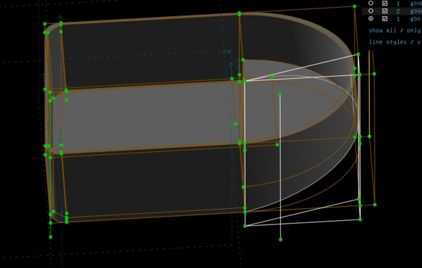
only part of the hull but this time smoother than version 1 which was really a box
bottom view shows the rounded outside and inside hull
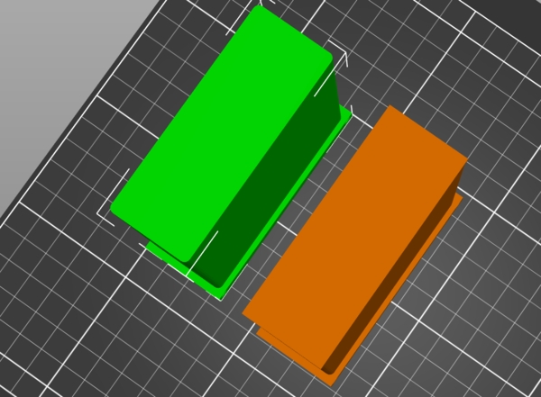
piece of the hull and battery holder
doesn't have to be perfect just want it asap
But anyway this fits very nicely
Might a bit too wide but let's wait and see. Two powerjet's and a battery in the middle should be no problem
Then updated my documentation until that moment.
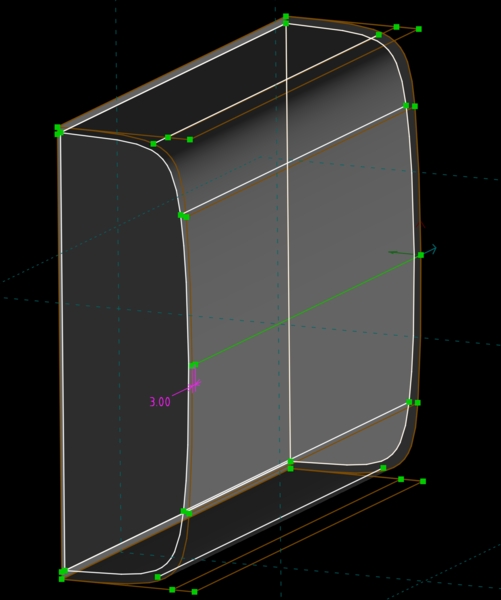
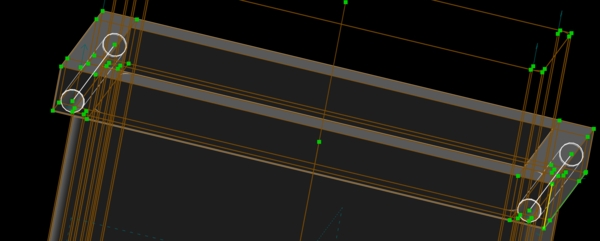
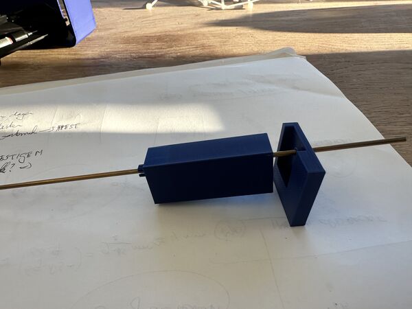
Visual design battery holder
one block with curved corners
created similar structure on the inside leaving a wall that's 3mm thick
So the holder will be under the bottom and fixated using silicone kit. But if the bottom of the holder brakes the power bank could slip out. So I wanted to enforce the structure by creating two crossbars on the side with a pin going through just for extra safety.
yes getting there
but .. not really cross
cross indeed
now even with hole
In PrusaSlice it all looks good but why only on two sides?
Let's make it 4 sides
yes much better
let's print this
BUT WHERE'S THE BOTTOM OF THE HOLDER??
back to work
ah yes this is what I want

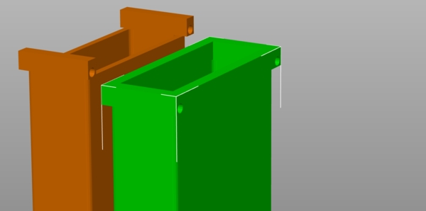
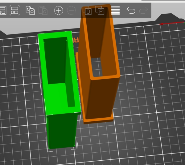
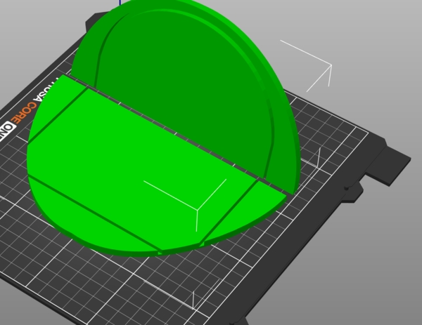
Oh no, straight corners :sad: This way it won't glide into the hole inside the hull
Back to work
Left (green) is the one I want
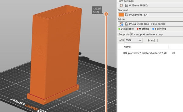
Finally let's print this version
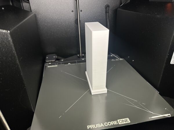
Took around 1 hour 45 minutes
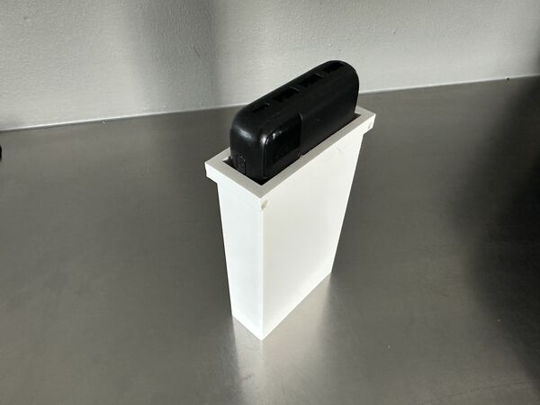
Powerbank fits nicely
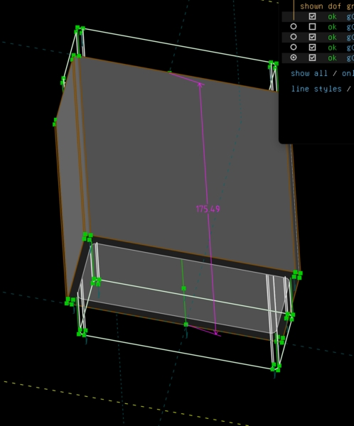
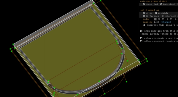
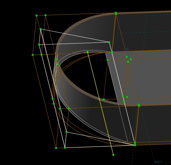
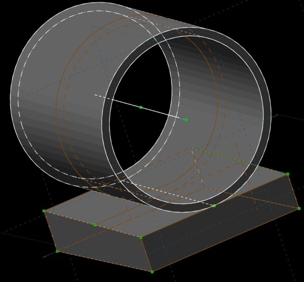
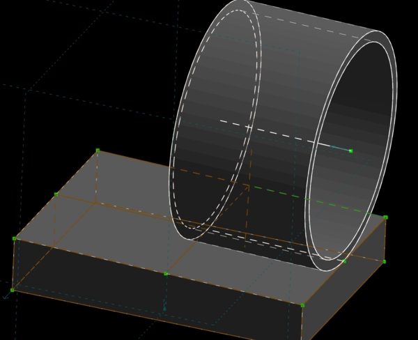
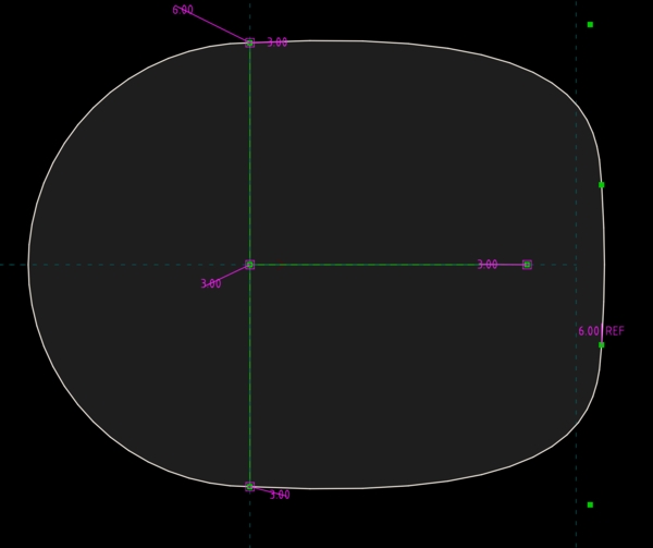
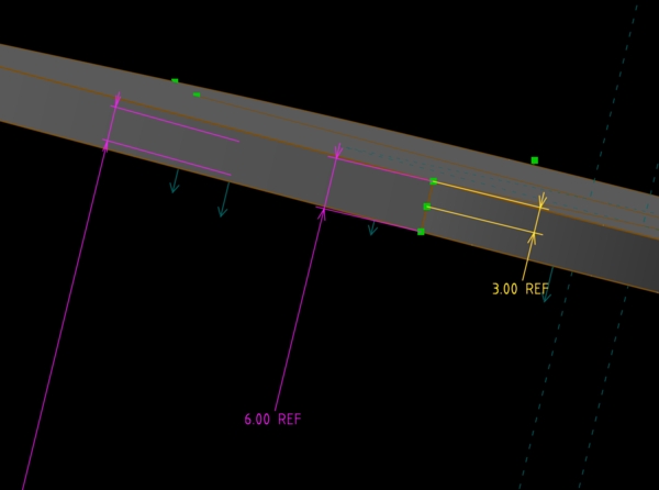
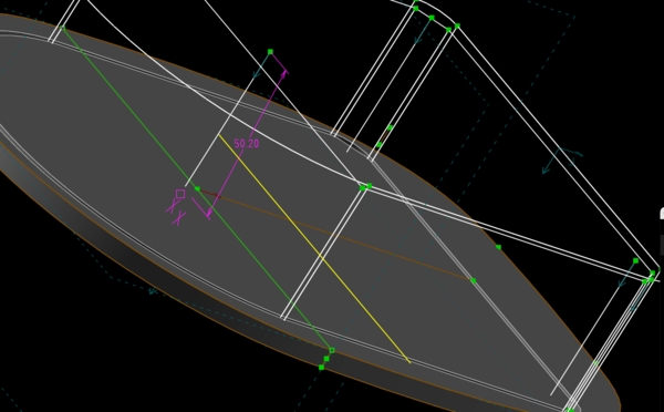
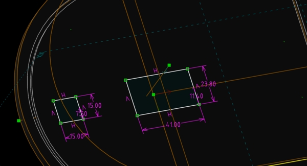
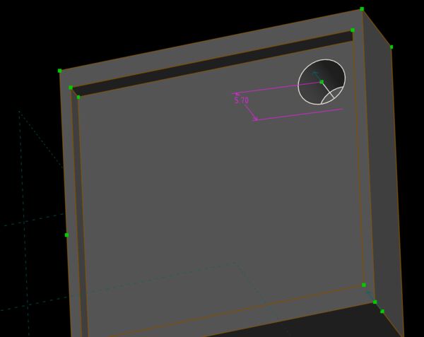
Visual design hull v3
With my notes/ measurements I went back to SolveSpace to model my hull; specifically the outer parts where the waterjets should be fitted. So a hole in the back and below. This time I described the process in week 16 assignment. To summarize I hgad Some of the images I've duplicated here as well
partly print to test fitting of the waterjets
looks good
to see in perspective of other components
at the end of the day
Week 17
Working on wiring
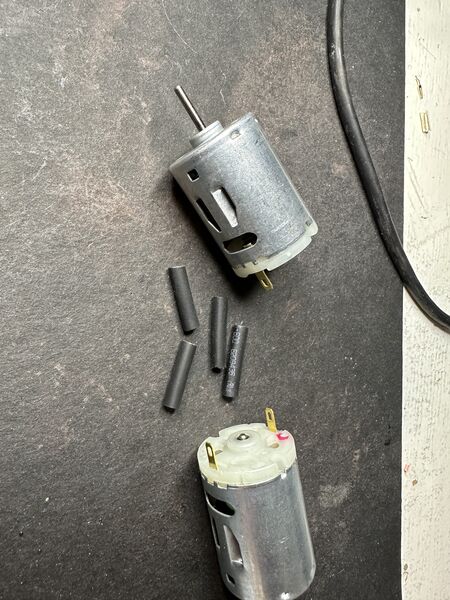
laying out the materials; heat shrink tubes; diameter 2.5 mm
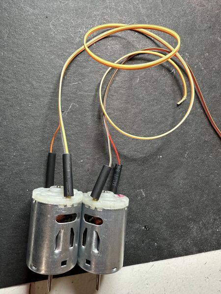
soldered wires to the motors and added shrinking tubes around it
heat gun set to 410 degrees Celcius
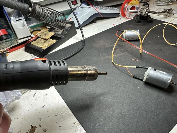
easy peacy ... just a bit of hot air
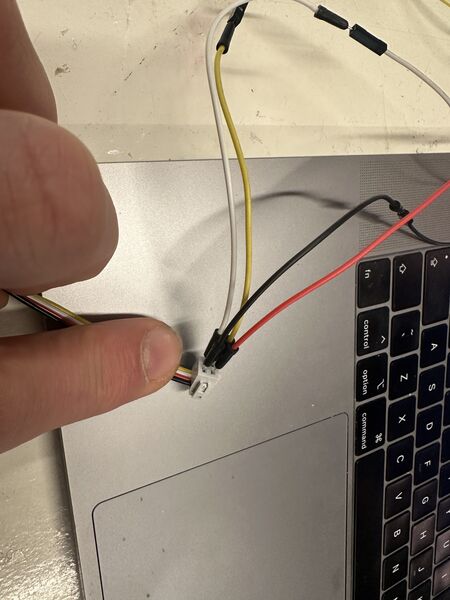
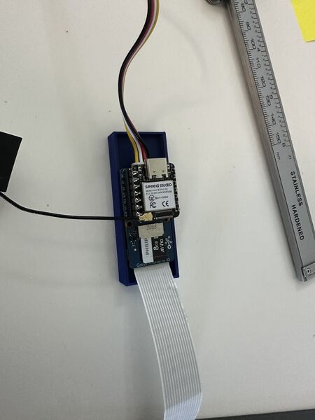
Then I changed the end of the Grove cable, the one coming from the Grove Vision AI module, to have the same type of 4 connector as the one I already attached to the GPS sensor earlier on
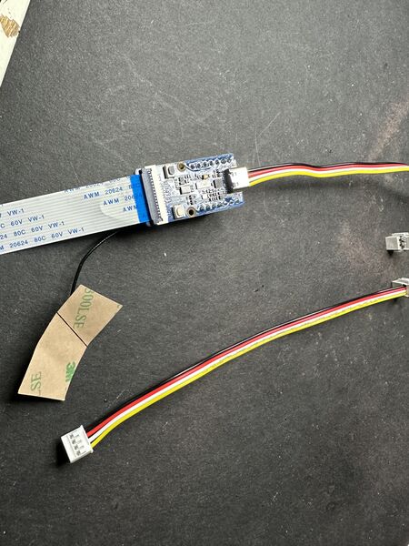
currently ends with propriatery comnnector
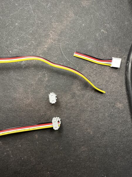
just cut it, add the connector and squeez it
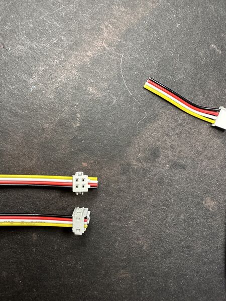
and voilá
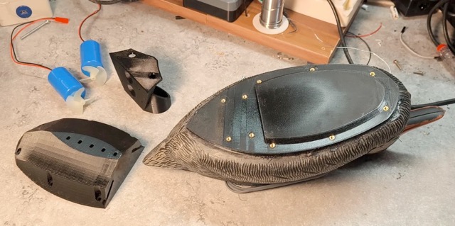
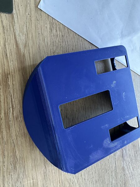
Visual design hull v4
My goal is to design the lid and see where I can put the electronic components. So I first inspected the outcome of the previous design.
Hmmm the hull is too wide; I could take 60mm off easily.
and too long; here I got also get rid of another 50mm
Improving this and maintaining the centre of gravity would help me reduce time to create the hull and make it nicer. Like the duck really sitting on top of the hull. Bit let's first start with the lid.
I drew the option of the classic idea of something that could be places on top with some kind of sealing on both sides of the "contour of the hull" .. And to close it and unclose it (to take out the battery etc) I decided to use bolts on the outside. Not everywhere but for instance 3 on both sides and 1 at the back.
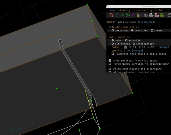
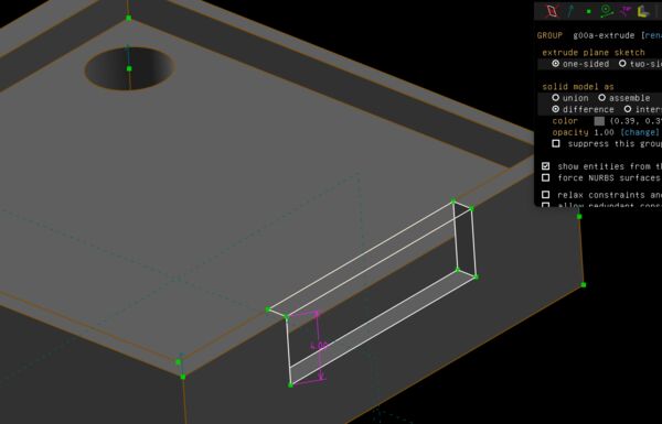
Experiment
I did some experiments in SolveSpace how to draw this. That was a good idea as I still mix up the boolean operations; it appeared to be a horrible exercise; took a lot of time. I started with some experiments in a new design
creating a mockup contour
making it only 3mm in depth
pretend a lid goes over it; using difference; it wanted to leave the inside is of the hull; now it just removes it
but intersection doesn't work either of course because it will keep only what's in common
Then I remembered again to start from outside in. So I created the bigger hull first(!) and then subtracted the outer contour from it
Yes looks promising
PrusaSlicer agrees; this is nice
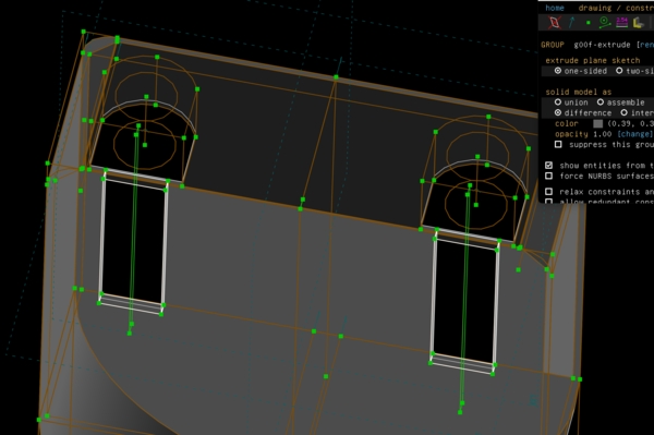
Ok now let's add areas for the future bolts to go through
works
Then I worked from the same idea to have a big area and subtract my design from it. So I first tried this inside my current design.
but as you can see it leaves me only with the contour; not the lid and inside the contour
So I fugured out that this can only be done by making a new design and linking the old one as assembly; then it could be treated with the option difference
This means however that I will have to copy the contour of the hull at the top and copy it to a new design later on. Because I can't now shift layers in my current design (or at least I can't find that option).
Experiment 2
So I thought to change my current design and then later make the lid; in the way I just described.
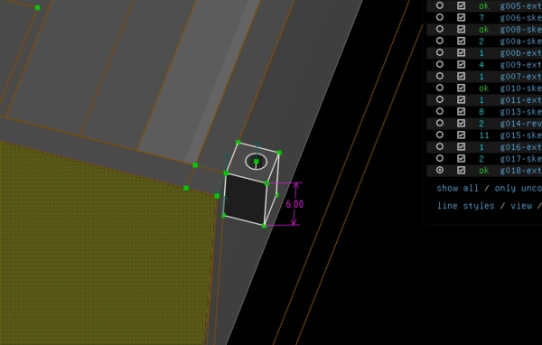
adding a bolt area
yes comes through all the way
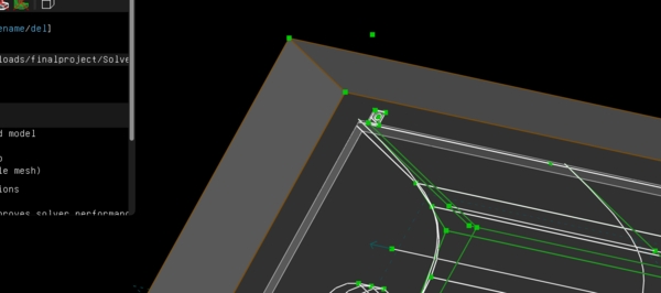
But then I exported the contour just for fun and viewed it in PrusaSlice
I could not lay it down because it was too big, even for a Prusa Core ONE (arggghhh). I can't print it that way. The only way to do that is to make the design smaller like I suggested earlier that day. So I started again with a new design. The big difference this time was that I really tried to WORK FROM OUTSIDE IN
Prusa likes it to and it can now be printed flat
Remark: I did stop the printer 2 times just before it would start
the area for the power bank is skewed
the opening for the bolts are to near the outlets
estimated time is 1h45m; that's 1 hour less than the previous design
It came out like this
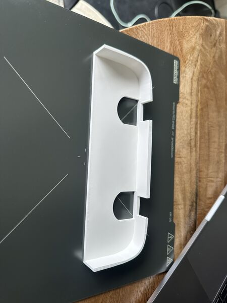
The lid
The next morning I subtracted the design from the extruded contour of the duck itself. Like I tried the day before. I printed this
view in PrusaSlicer
ended up like this
fits very well on the outer side of the hull
much nicer shape overall design despite the 2 holes at the back
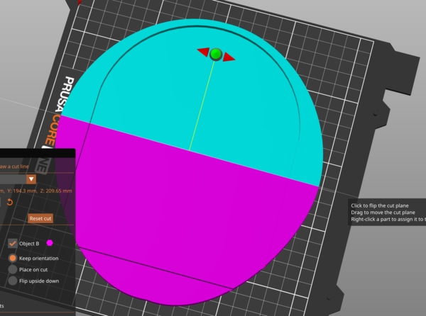
PrusaSlicer trick
When in cut mode you can use the SHIFT to draw a line in a plane. This will cut it right were the line was drawn. That way you can just try out parts of the design and not print everything all the time
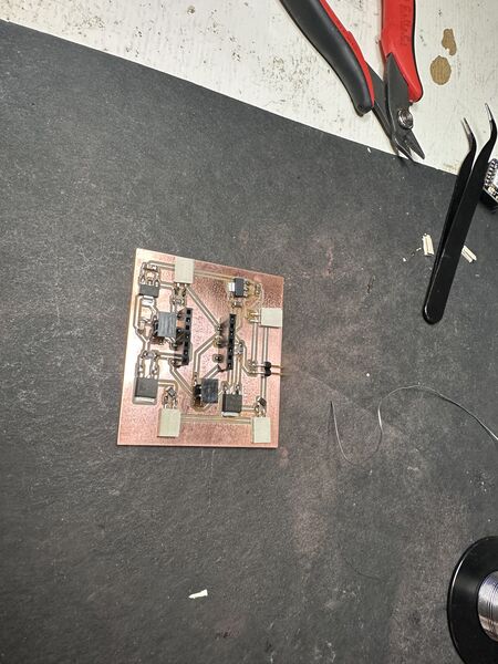
PCB Navigation
After our group work regarding the use of composite materials I went on with the design of navigation pcb.
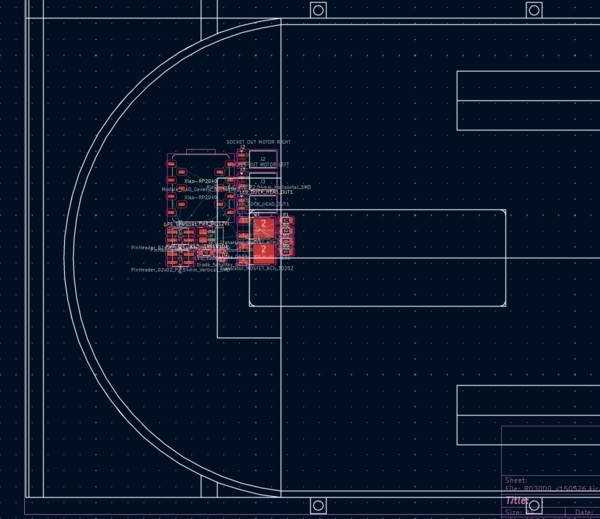
I exported my hull design as DXF and used this as background to layout mmy PCB
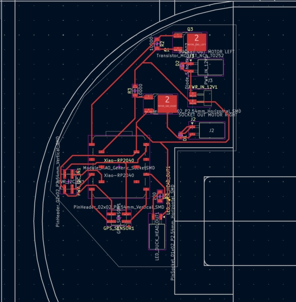
It took me 2.5 hours to get it in a shape that would meet all the rules
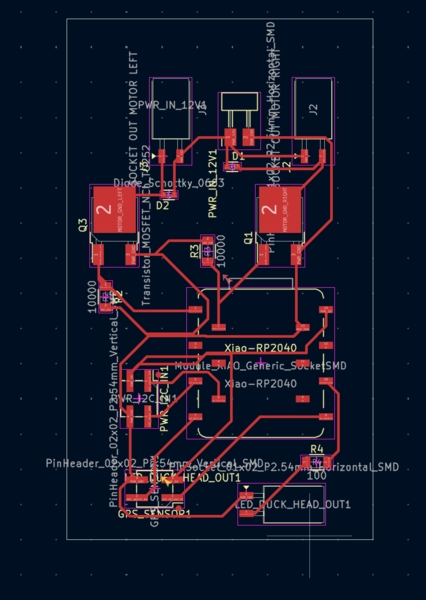
Just before milling it I decided to save space for now and make it like a rectangular. If it works then I can always adjust it for the shape I need and mill second one.
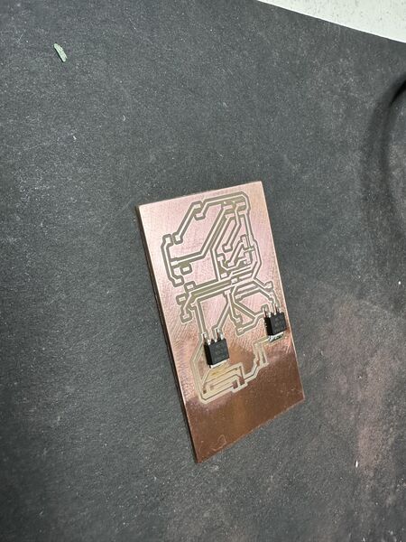
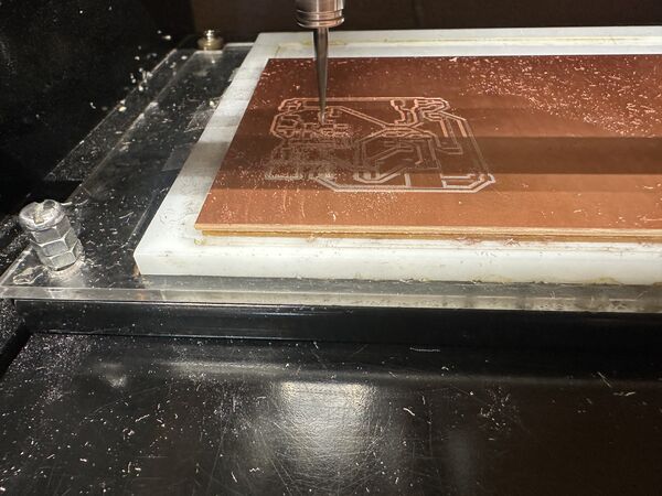
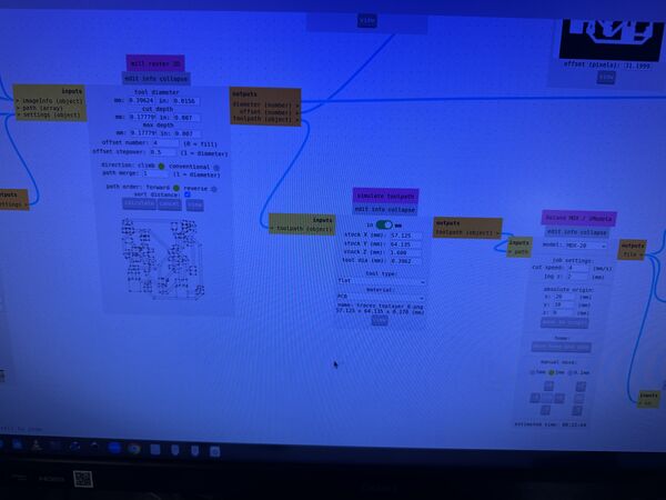
Milling the PCB Navigation
Because Remco had some problems this week I discussed his latest settings. Based on this I used a cut depth of 0.004 inch instead of the usual 0.003inch and offset 4 (as usual).
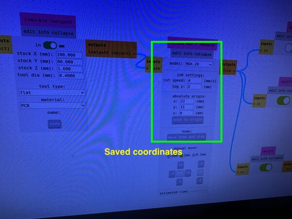
saving my home position before milling the top layer
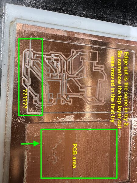
the cutout went right through by pcb??
Henk and I discussed how this could have happened but we ended up having no clue. Just try again. Restart the browser. Also Henk mentioned that the top layer was not cut deep enough? Again strange. Henk releveld the bit in the middle of the PCB(!!) using a paper to see if it was bearly holding it. After this i tried again.
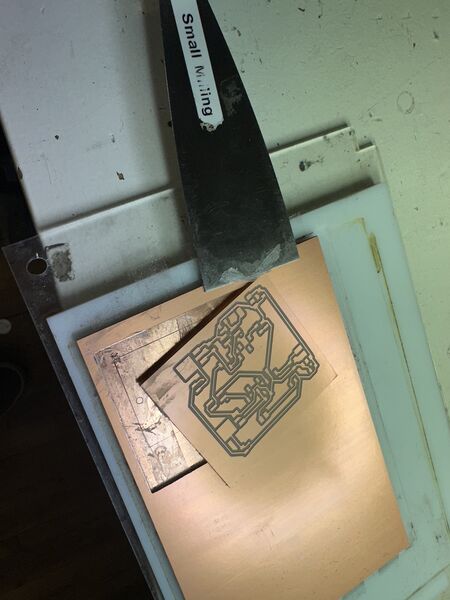
Even then the top layer was still not milled properly; much better than the first time though. Henk suggested to mill it again using 0.005inch cut depth.
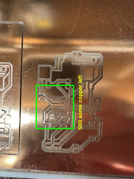
even after using 0.005inch cut depth it was still not entirely ok. I removed this by hand with a very small screw driver
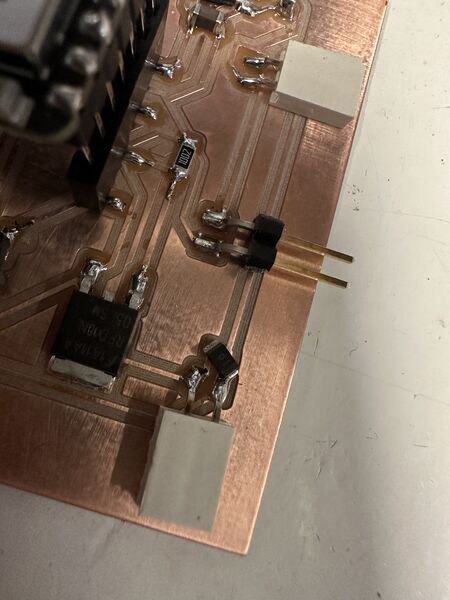
Soldering the PCB Navigation
Both MOSFET's have a surface that needs to be soldered onto the pcb area itself.
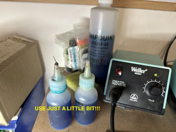
Henk showed me how to use a bit of FLUX on the spot
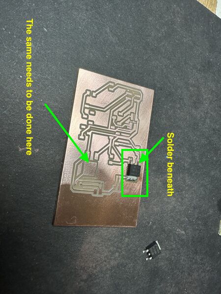
Then put a little solder on it which flows all directions (because of the FLUX)
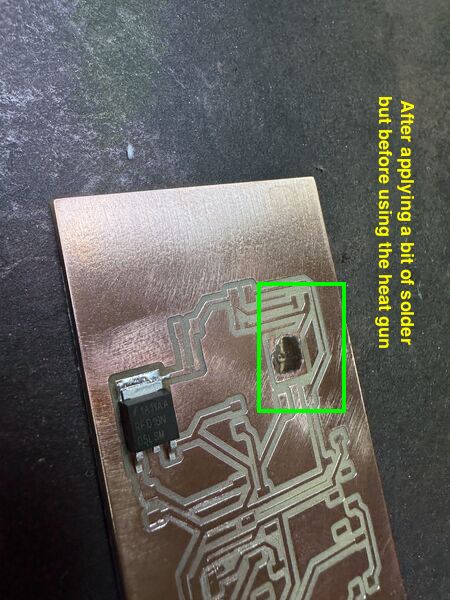
After which you place the MOSFET on top of the solder and use a heat gun to make the solder soft again. And voilá
This time I tried myself
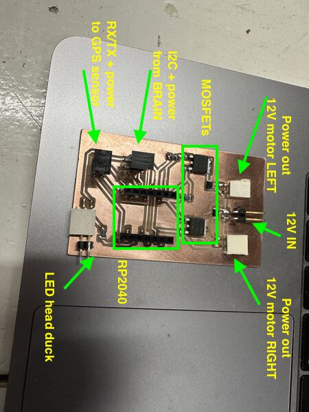
All the pieces on the board
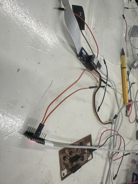
Testing the PCB Navigation
In the evening I saw that at least the power line worked
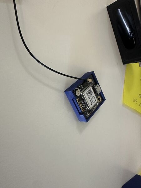
The ESP32S3 (on the left) is powered by a USB cable. From there the RP2040 is powered and from there the GPS sensor
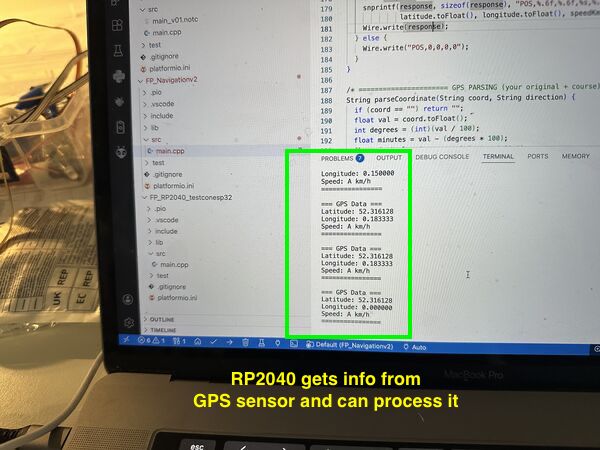
Then used some old code to see that the RP2040 could still communicate with GPS sensor
Note
The ESP32S3 could communicate via I2C with the RP2040 so that's good. I then tried to get power out of the MOSFETS. Basically I got something but it is either 12V or nothing. Work in progress.
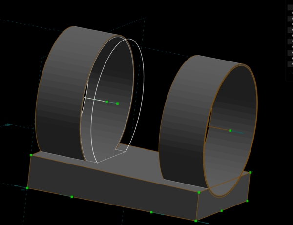
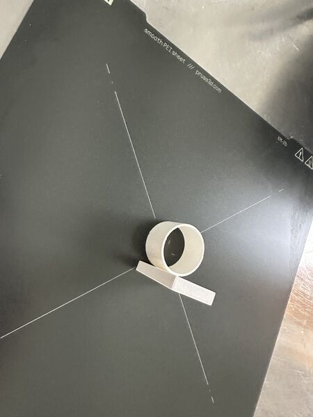
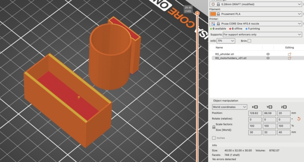
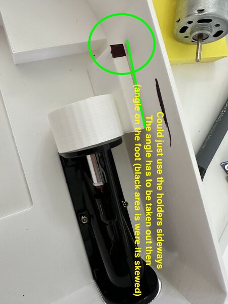
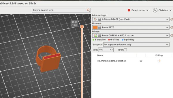
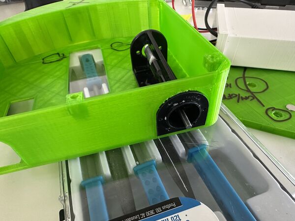
Design motorholders
the space I have to mount the motor; as it is very little I can't just slide in a motor from aside; so I'll create a holder that I can later glue inside
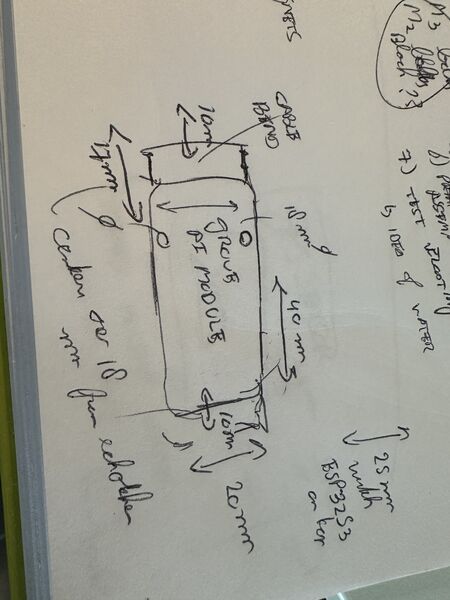
Started with a design in my sketchbook after measuring everything. My idea is to have 2 rings: one at the front and one at the back leaving an opening for cooling in the middle
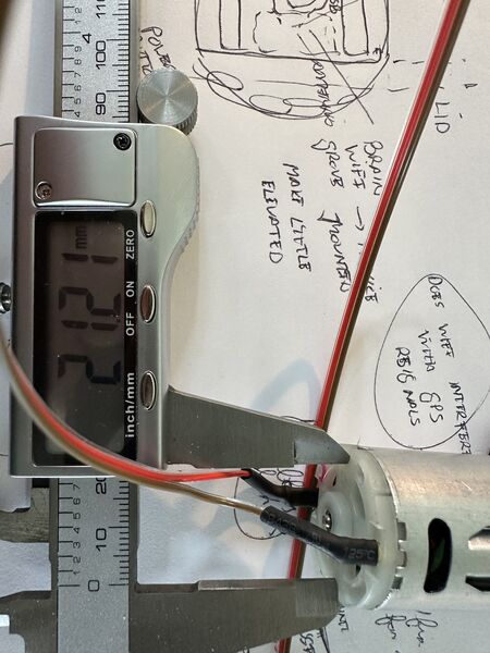
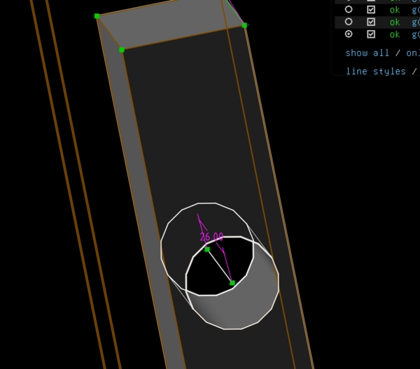
diameter 27.2mm; near the waterjet 3mm elevation; 4mm near the other side. So it's angle is skewed.
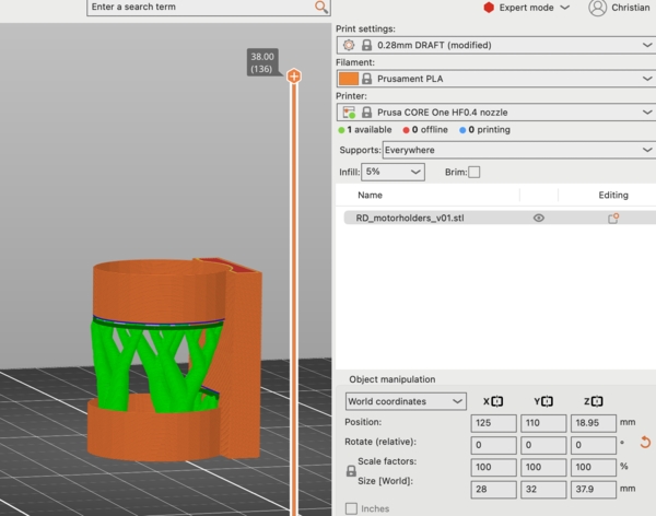
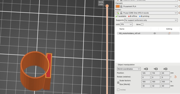
sliced with organic support
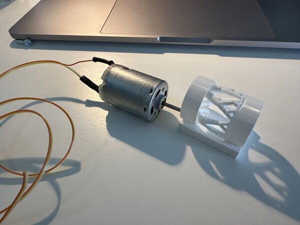
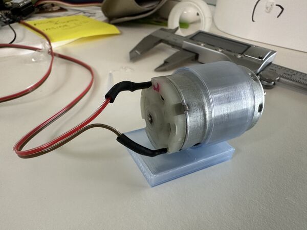
after it was printed
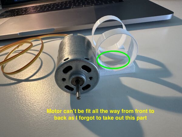
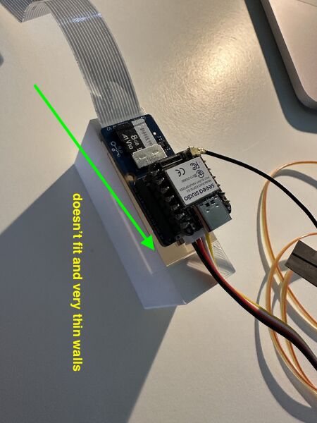
Problem with this design: a) too thin and b) forgot to have the outer hull all the way through
But I the because the centre line was skewed the circles would not match. I didn't know how to make a tube in a different angle
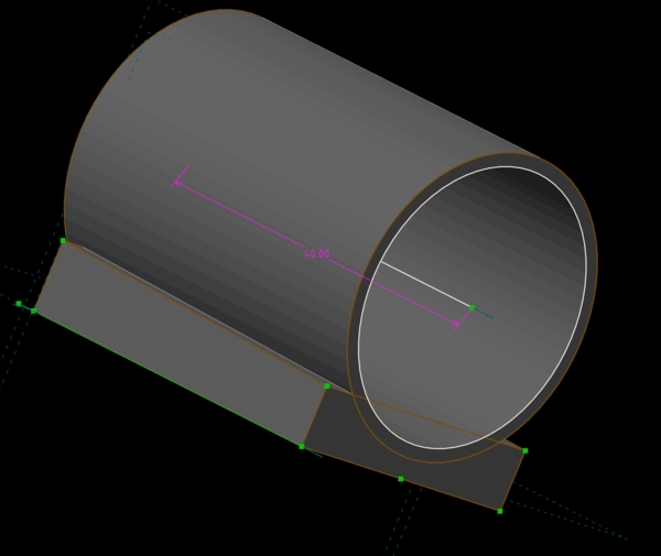
So I went for 1 tube all the way through; that way I would now it would at least fit; but the angle would probably be a bit off
this time no support needed as I printed it on the side
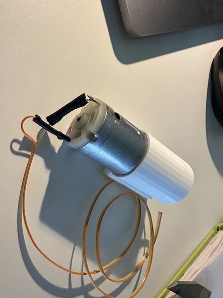
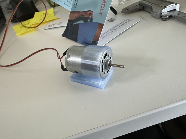
came out nicely but it was way to narrow for the motor to fit in
So extended the inner ring diameter and tried again
well yes it did allow me to fit in the motor but it was stuck
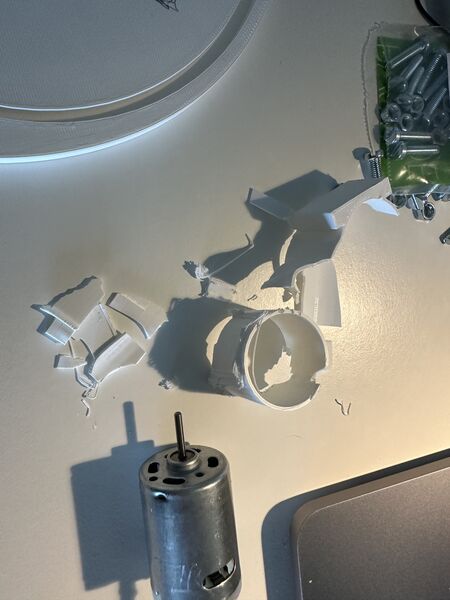
had to brake it apart with plyers
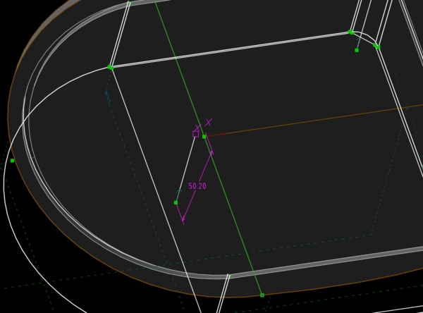
But before just printing a newer version I want to solve the angle; I managed to do so creating a seperate plane that was skewed and used that to draw the outer and inner circle
so the centre axis of the circles are now in an angle
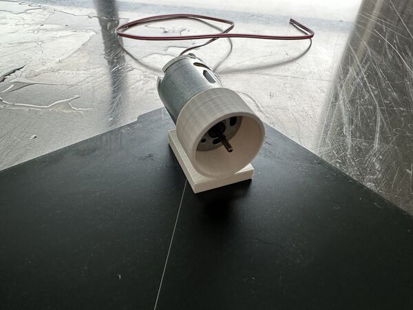
and decided to allow the back of the motor to cool and only attach it at the front; for this reason I made the outer wall thicker
After printing this it the inner diameter was still to narrow; why?
you can see the angle from aside
So I printed a new one (again) but still not ok; huh????
I measured the inner diameter of the last version and found it to be 27.3mm exact as specified in SolveSpace; amazing! But it should be at least 27.35mm as I measured the diameter of the motor again. Well yes that explain a lot. I now changed it to 27.45mm. It is still very tight and if the motor heats a lot it will expand. So I will try another version with 27.55mm inside diameter.
Design Grove AI module holder
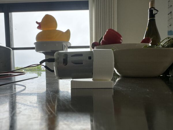
Parallel to printing the motor holder I worked on a holder for the Grove AI module v2. As it has the ESP32S3 chip on top with Wifi, I want it as far away as possible from the GPS sensor and a bit elevated from the bottom in case some water comes in.
First again on paper
I iterated through a couple of designs and printed it almost right away; sometimes with the motor holder together.
version 1
2nd version
3rd version
so the whole construction rise above the top level
I printed a 4th version which is now ok.
for the motor holder and this holder I quickly printed it using .28mm PLA, 5% infill and only neccesary support
result
Lid with magnets
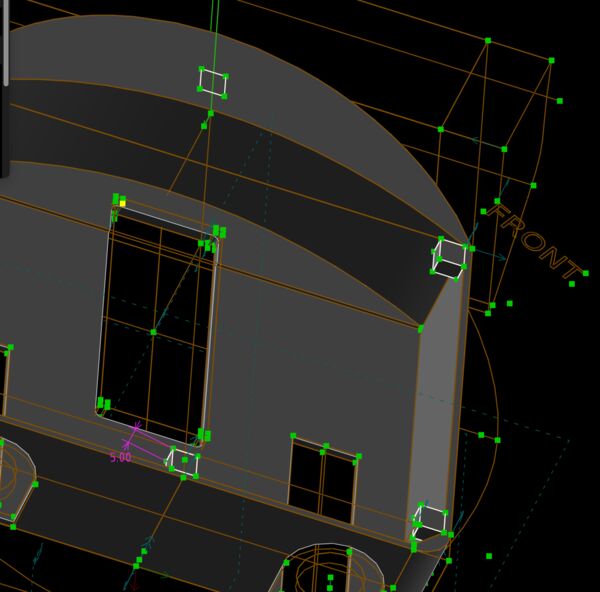
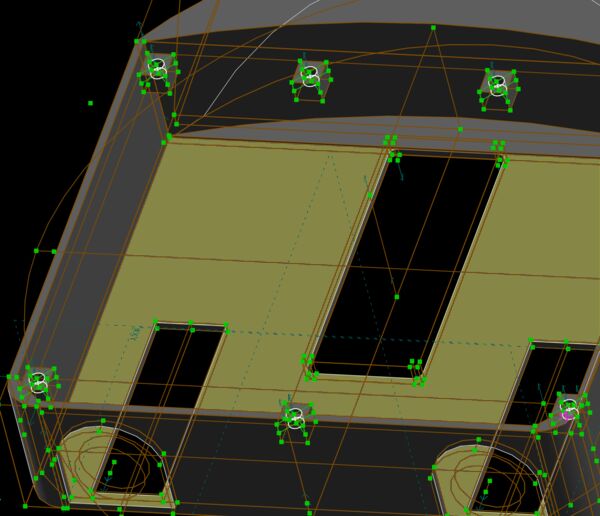
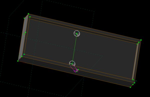
Before working on a 2nd version of the lid I went over the design, got rid of (almost) all degrees of freedom and found that the centre line of the power bank was not exactly the middle.
a bit of centre
I found a new way of creating the lid:
I used the normal trick to point both the lid and assembly object in the same direction
using a circle and a bezier curve to match the duck's contour
extruded this to 6mm thicknes and created a plane inside at the middle
subtracted the platform as assemly object and attached it to this plane
then place insert for the GPS antenna at the front
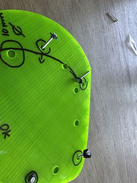
then designed place hodlers for several magnets
and marked the duck at those places
Floating experiment
Bringing it all together ...
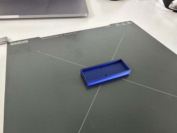
latest version printed during the night
battery holder fits more nicely; still overhang type of problems at the front but I didn't use support so that might explain it
the new lid sticks to the top like a brick
for now just tape it
also this of course
centre line of the duck seems to match the centre line of the power bank
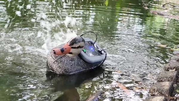
When I put it in the water ...
Houston we have a problem
So it needs weight .. and I don't want to put in my power bank just yet. It ways around 390gr.
replaced the power bank with screws that weigh around 400gr.
ready again
ok no flipping anymore; but it's skewed?
So the cause is most probably a bit of balance and the fact that water was coming in that choose one side to go too
somehow the tape is not good enough
But I have another issue ... the water jet intakes are under water but the nozzles are not. No thrust if it's just throwing out water in the air. I need more weight for now.
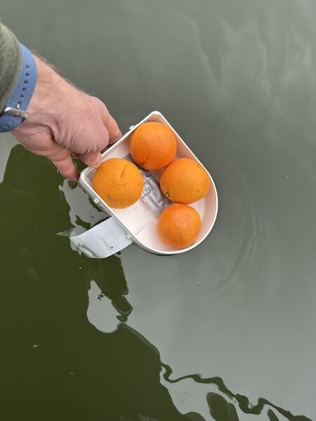
I found that 4 oranges actually are enough (without the duck even)
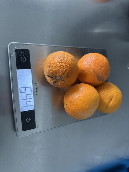
they weigh 644 grams; that's another power bank at least
Week 18
Back to PWM
So at least it does something; but why again?. To be honest, I'm a bit rusty on explaining Pulse Width Modulation to myself so I looked up the standard Arduino documentation about this subject.
Pulse Width Modulation, or PWM, is a technique for getting analog results with digital means.
So digital control is used to create a square wave = a signal switched between on and off
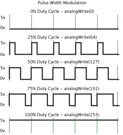
src: https://docs.arduino.cc/learn/microcontrollers/analog-output/
So in case of PWM frequency is set to 500Hz it means that each green line represents 2msec (2 miliseconds; 1/500). The value I set via analogWrite() basically means that I tell the microcontroller how much of the time I want it to set this cycle to on.
In my case, were I use it in combination with a MOSFET, it will produce an average voltage to run the motors; like with the LED dimming exercise we did a while back.
But what frequency should I use? It doesn't say anything about the frequency that is suitable for DC brushed motors though.
I found this article.
Rotor coil inductance becomes an important factor to consider when using PWM for motor speed control. The motor coil works best when the applied voltage is relatively steady since it needs time for its magnetic field to reach the needed strength. At higher PWM frequencies, the pulses from the motor controller board change too quickly to provide enough energy to spin the motor ... When the PWM frequency is lowered, the motor’s coils extract more energy from the pulsed PWM signal. That means that the motor will start spinning at a lower equivalent voltage and will operate with improved torque at low speeds.
The article even mentions a frequency of 20Hz or, if this leads to too much chatter, use 400Hz. But it also refes to a geared motor.
My take on this:
- Higher PWM frequency means that the motor has less time per pulse to build up power to move; lower torque; but smoother operation
- Lower PWM frequency means that the motor almost reacts right a way, higher torque but may feel/ sound a bit rough.
So when silence is the thing I want (and I want this) a higher PWM frequency is preferable. But does it have to be 20kHz?
Let's test all of this.
I therefore did a small experiment performing the same loop at different frequencies:
- 20Khz: fine, spinning start audible around a value of 30
- 10Khz: smiliar to 20KHz
- 5000Khz: a distance anoying sound is in my ears which disappears when the value reaches around 200
- 2500KHz: even worse than 5000Khz
- 1000Khz: I hear the motor having trouble; it doesn't like it
- anything lower than this ended up in a lot of noise and poor performance
So start 20Khz is good enough for now.
Testing the motors
I hooked up one of the motors to the right output and run a small PWM program consisting of
// setting the motor pins as output
pinMode(MOTOR_LEFT, OUTPUT);
pinMode(MOTOR_RIGHT, OUTPUT);

// setting the PWM frequence to 20kHz
analogWriteFreq(20000);

// then use
analogWrite(MOTOR_LEFT, <number>); // this to increase the duty cycle and therefore increase the load on the motor
I ran a loop increasing from 0 to 255 and have small breaks in between them. Well the good news is that motors actually work/run.
At full speed the motor draws around 0.18A of current at 12V; given that is has no workload at the moment!
Note
When at max they draw each around 0.18A at 12V. I even tried to stop one with my fingers and that was difficult to do but then the load increased to 0.35A. When I really tried to stop it I burned my fingers a bit and the current reached around 0.9A.
Note
I measured the amount of decibels between a frequency of 20kHz and 10kHz. Although the 10kHz sounded/ felt a bit louder it was around the same; between 69-71 decibels.
I then tried to increase the range to 270 but found it didn't matter; a value of 270 gave the same loudness/ result as 255.
Note
Looking up the function analogWrite() this makes sense. The value has a range of [0,255] = the duty cycle: between 0 (always off) and 255 (always on). Any value higher than 255 doesn't make a difference.
Next related function is analogWriteResolution(). Looking it up I found
Its meant to
leverage the full range of the DAC and PWM outputsIt defaults to 8 bits (values between 0 - 255) for backward compatibility with AVR based boards. The value can range from 1 to 32
The microcontroller is the limiting factor. So if it supports 10bits resolution this means it slices the PWM duty cycle in 1024 steps.
analogWriteResolution(10); // sets the resolution to 10bits
analogWrite(<pin>, map(<value>, 0, 499, 0, 1024)); // given the value has a range between [0,499]
So how about the XIAO RP2040? Time for its datasheet. Paragraph 4.6 mentions:
It has 2 PWM channels A & B GPIO's are attached to either A or B A channel can be set to a certain frequency (paragraph 4.6.2.4. Clock Divider)
Do I need to set different frequencies per motor? No I don't so using the standard analogWriteFreq() is enough. No special libraries needed specifically for the RP2040.
Next I need an idea whether or not the resolution makes a difference. I therefore made some code to experiment with 8 and 10 bits resolution. My conclusion it that you build up more slowly to the amount of power you want to apply BUT the final output stays the same.
Another question is IF, once I set a value via analogWrite() this remains that way until I set another value. The idea is that micro-controller can do other stuff in between.
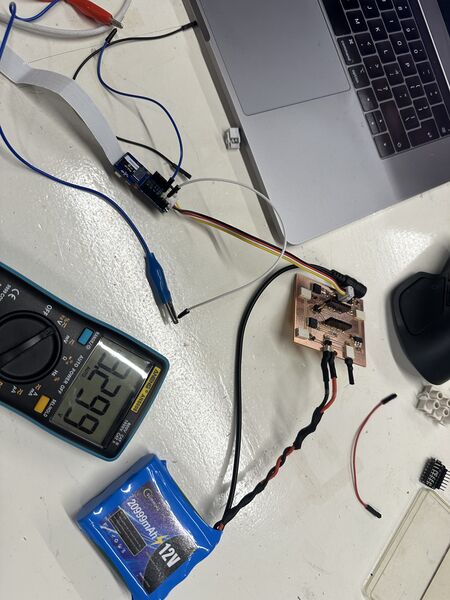
Power
I also found the my powerbank just stopped when the current stayed below 0.05A during a longer time. For this I also did a small experiment. I set the motors to 20% during 1 minute; this lead to the power bank turning off. Jaiks ...
I therefore connected everything to see if it would draw enough current to keep the powerbank going.
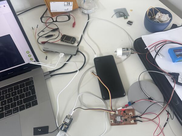
I found out that when I connect the USB output for my 12V to IN/OUT USB-C type then on the display PD shows in green. Now it is still running without a problem.
And what if I connect my micro-controller to this same output? So I connected the brain via USB-C to the powerbank and watched it for a while. It kept running. And on a type USB-A output? (reason for this is because I have just one USB-C type of exit on this powerbank). And after 10 minutes it was still running.
Note
Hooking everything up led to the burn-out of my ESP32S3 :sad: ... The only thing I can think of is that it somehow got more power on a pin then it could handle. Because instead of hooking up the ESP32S3 to the USB power directly (as designed) I hooked up the RP2040 instead. I did a test earlier which was not a problem but I guess I must have turned the connector around somehow. Anyway, it was still blinking though; no white smoke or something.
Note
When I hook up the RP2040 to the USB-C directly it throws out 5V to the GPS sensor. According to the specs this should not be a problem. I see it's blinking again so never mind.
When I both hook up the motors and the brain to the powerbank then it defaults to 5V power that is requested by the brain. So this means that I have to use a different supply for the motors; luckily I already thought of this a while ago and it arrived today.
Lessons learned - design updated
Lessons learned sofar:
- frequency 20kHz
- 8-bit resolution
- connect 12V to the USB-C type of the powerbank to power the
brain - power the motors via a seperate 12V source (which I ordered a while ago and just received)
- use the cables as designed to power the rest
My final setup will probably look something like this. 12V from a seperate battery and 5V from the USB-C socket to the brain via the powerbank
GPS sensor
Most of my morning on Friday I spent on getting reconnected with my GPS sensor. I measured if it would get power, I revert to very simple code to read it, I read the manual again. But because it already worked again a couple of days ago I was really lost.
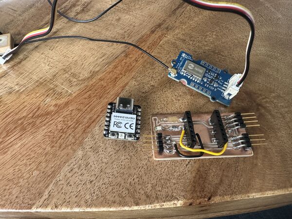
Attached pins directly on the cable of the sensor but couldn't get any reading out of it
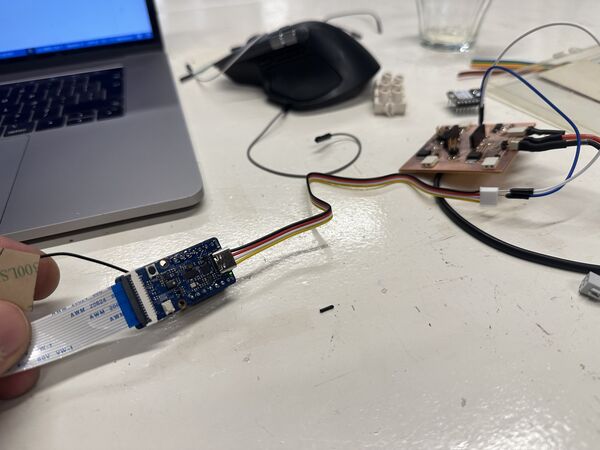
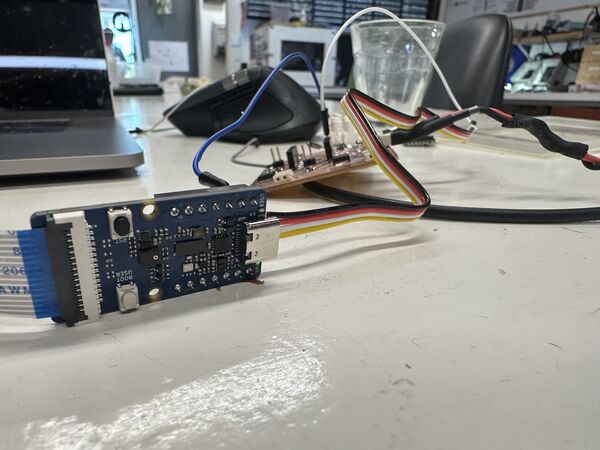
I therefore just tried a completely different GPS GT-U7 GPS Module. I soldered the pins onto it and gave it power via a small micro-usb connection. When I started the serial monitor instantly I saw data. I then wrote some code to work on the ESP32C6 and there it worked as well. I then switched to the RP2040 using PlatformIO and just changing a few lines of code it worked there as well.
GPS sensor connected directly on the pins of the ESP32C6
Yes ... I'm getting data
My guess is that it might be the cable and/or attachment that's not working or I also burned this one to the ground yesterday.
Result ... appearantly one time per second, less than the Grove sensor .. but fine for now
Wifi access point
Henk gave me a new ESP32S3 to which I soldered pins. I then referred to old code I wrote a couple of weeks ago were I made a hand-gesture game using the ESP32S3 as Wifi access point and front-end code that I uploaded via little filesystem. So I spent time on cleaning that code up as a base for my Roboduck3000.
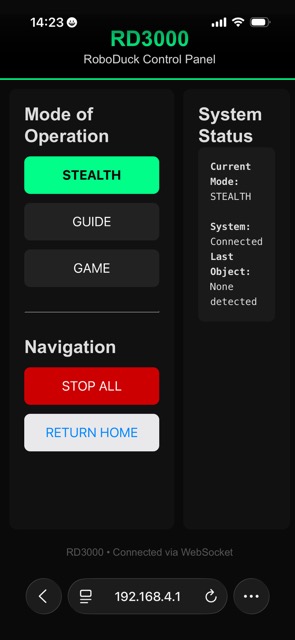
I asked help from AI to generate the UI front-end code. This time I didn't want a ps5.js library as it was way to heavy for it's purpose and it took a long time load from the ESP32S3. It gave me a nice simple colorfull interface.
I worked on the code until it was sending every command from the UI to the Wifi server where it showed up in the serial monitor.
Hooked up the Grove Vision module again and that worked as well (still ;-))
Now I want the brain talk to the navigation unit. So I added just a piece of code in the brain's code
    Wire.requestFrom(I2C_NAV_ADDRESS, 6);    // request 6 bytes from peripheral device #8
    while (Wire.available()) { // peripheral may send less than requested
        char c = Wire.read(); // receive a byte as character
        Serial.print(c);         // print the character
    }
I then updated the code for the RP2040 to always respond something (at least 6 characters). This was based on the experiment that I saw the master send a request only once. But of course looking at the loop above this is normal. I would send "" (empty string) so it just waited there.
The brain asks for detection of images from the camera via the AI module. At the same time 123456 means it get's a response from the navigation unit after it asked for an update
My short conclusion is that my PCB is ok. I attached the wires exactly like my PCB and the system is just working.
Back to design of the parts
On Saturday morning I first sat down and started with notes on what I still had todo.
current design of the motor holder can also be placed on the side wall; it needs to be flat thought then
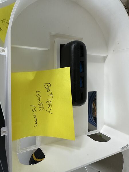
I want to lower the whole hull by 15mm. This means the duck will come down as well making it more near the water and less wobly. So the power bank needs to be lowered
Somehow it is still difficult to fit the waterjet in at the back. Needs a bit more space there
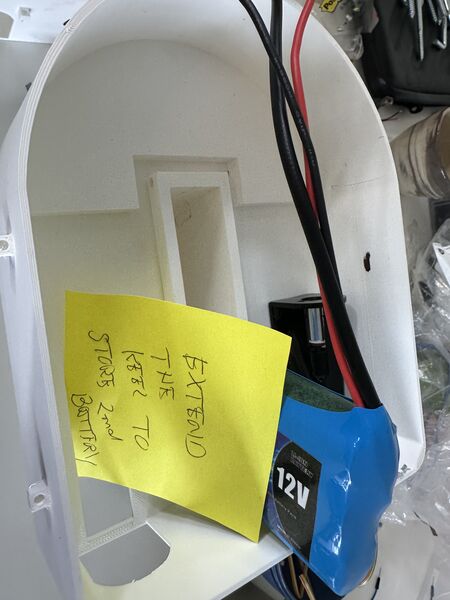
Yes now I have another battery to store. Where do I put it? My thought now is to put it in the keel behind the power bank
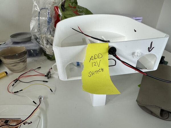
To turn on/off the system I'm using a magnetic pogo pin. I'll place it at the back
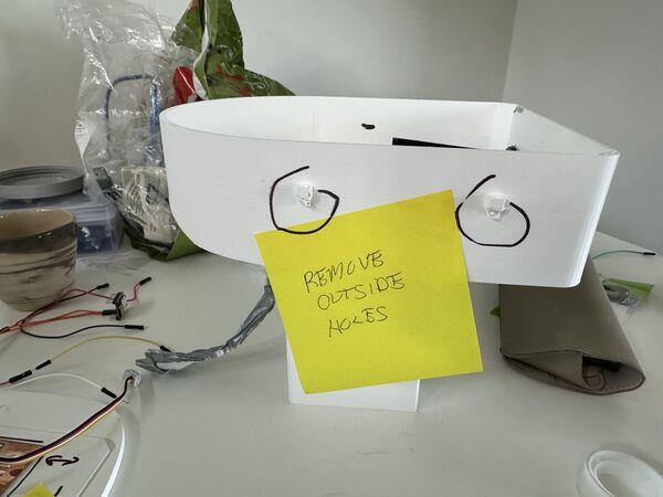
Based also on input from Remco and Heleen .... I'll find another way to attach the lid to the hull but these things have to go
I basically picked these up one by one in SolveSpace.
Motor holders
In between I adjusted the motor holder and printed newer versions using transparent PETG filament (just to see what it would do).
Remark: The filament I used was from a Dutch company Real filament. They provided special config files for their filament which I installed on Prusa slicer according to their manual. Yes I saw a list but as soon as I selected my own 3D printer they were gone. So I choose the Prusa PETG config for now.
Tweaking in SolveSpace
Doing a quick fit test using .28 draft and 5% infill with no support
This one is still a bit too wide (but very nice though)
Good fit on the second try
Overall length and height of the hull
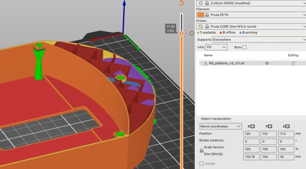
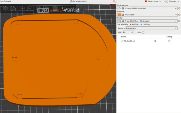
Back to picking up the changes I also changed the overall length/height of the platform; no reason to have a lot of air inside when it's not needed and it also lowers the centre of gravity. Because I also wanted to test the water proofing my idea was to now print at 0.2mm instead of 0.28 to reduce the width of the holes inside which enable the Dichtol to do it's work. And I like the motors I wanted to use PETG for the hull as well because it would make it lighter.
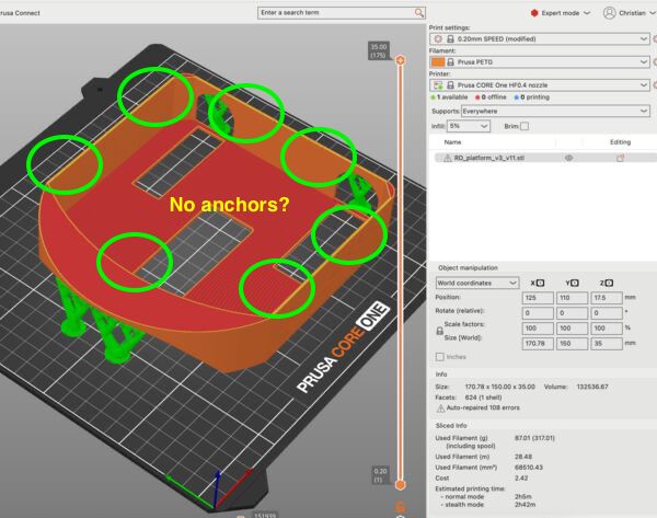
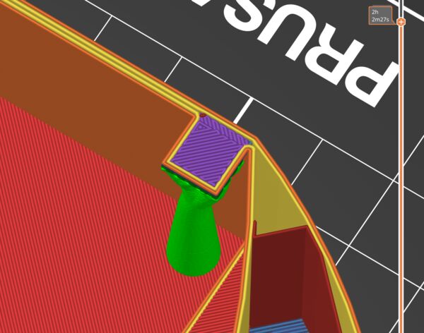
using 5% infill, 0.2mm and organic support; looking good ... but wait no way to attach the lid where are the anchors?
But just before I pressed start I remembered to also adjust the system by which I close the lid. I want to bolts going from the top from the lid through the lid to the inside of the hull were there are nuts.
lowered the anchors 4mm down to not interfere with the lid
I want to place nuts here using the pause option in PrusaSlicer
But most probably the support will be in the hole!?!? Let's just try
Indeed, there's filament support so no place for my nut. And the hole is too little also.
I then designed the lid and printed that
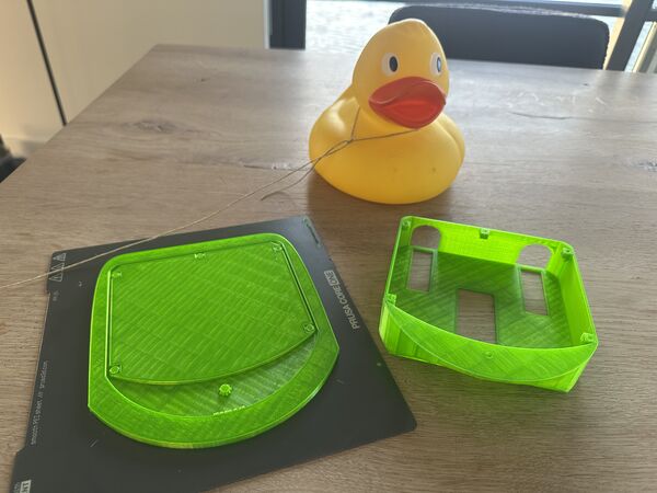
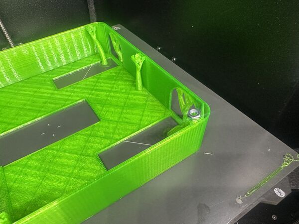
Result at the end of the day
Next day I inspected everything more closely again. It needs some tweaks.
on top the holes for the bolts should be a bit wider so theh fall in like the magnets / /the
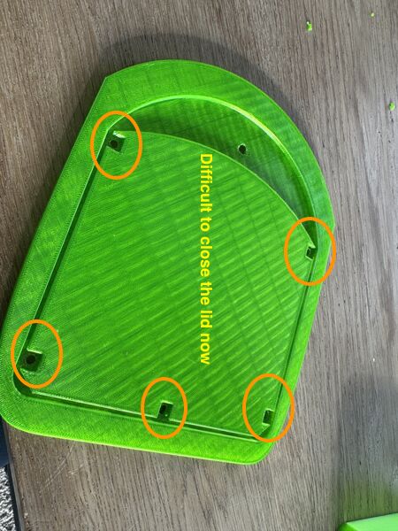
The squares make it difficult to close the lid; should lower them
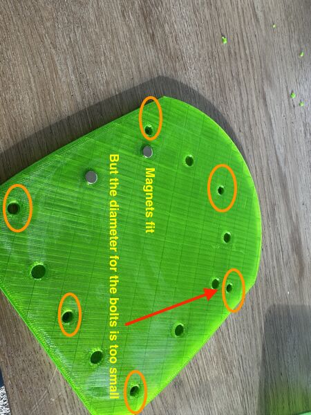
magnets fit; bit more space is ok as well
Inner hull were the bolts should be attached should be lowered 4mm so they don't interfere with the lid (now one of them broke off while opening the lid again)
Because it's all very tight it broke
Again making notes for myself
move the formost bolt more to the inside
waterjets do fit
Back to design and printing again; making adjustments according to plan
lower the anchors
floating anchors? No that's not a good idea
give them some body
yes that's better
So the result
And the lid
Later on I also made a small test object with a lid.
The idea is to have a bolt going all the way through the hull from bottom to top. It is possible
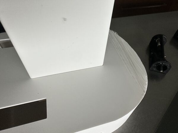
Waterproofing
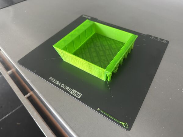
I created a small test object to simulate the hull
And used Dichtol to make it water proof; letting it dry for around 3hr (as it's 1mm per hour)

Put it to the test in water and leave it there
Next morning was still dry
Below you can see the stuff that dried up
And to complete it all I took some tube from a bicycle; plan is to use this as seal for the bolts
Converting 12V to 5V
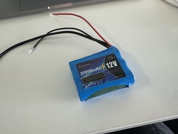
I've to make a decision regarding power.
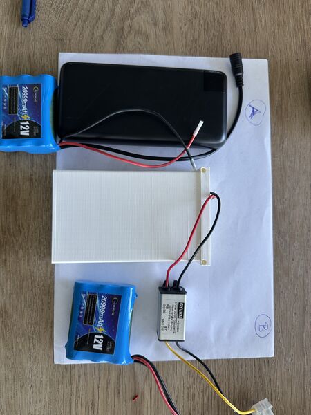
I can combine the powerbank (5v) with a 12v battery OR I can just the 12v battery and use a buck converter/ step down converter to create 5v from 12v (the one I show is something I have at home)
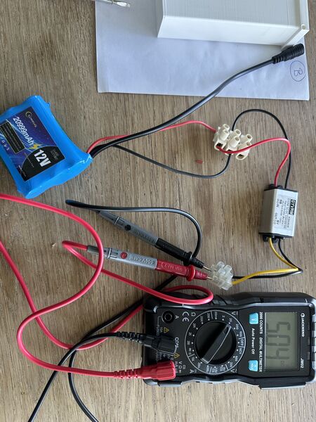
the step down works
And the RP2040 is able to get 5v IN on it's 5V pin (the ESP32S3 does NOT allow this)
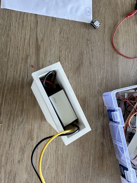
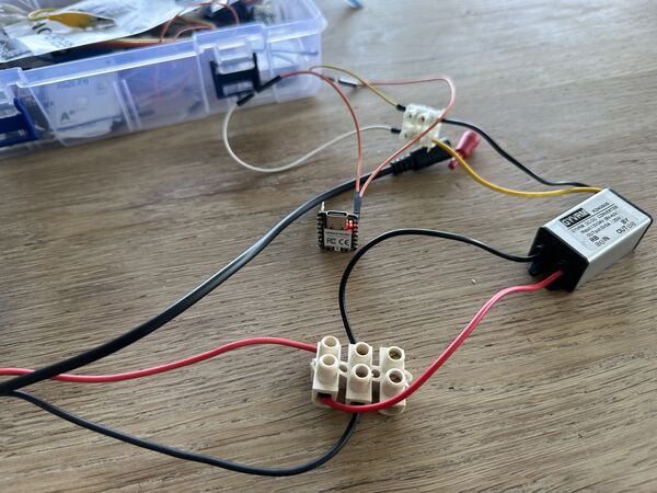
And the 12V fits nicely into the holder I already designed including the converter
So 12V it is
So at our Fablab I showed Henk my 'off-the-shelf' solution for the 12V to 5V conversion (and the RP2040 can take 5V as input on it's pin and yes I can store this converter inside the battery holder).
"But Henk, it must be possible to make it smaller right?"
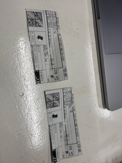
And yes indeed, Henk provided me with a couple of links to so called voltage regulators that are available at our Fablab:
- https://www.digikey.com/en/products/detail/diodes-incorporated/AZ1117IH-3-3TRG1/5699682
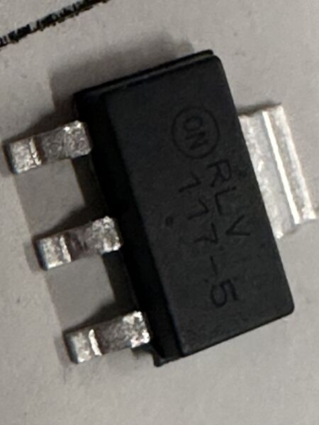
- https://www.digikey.com/en/products/detail/onsemi/NCV1117ST50T3G/1792666
- (towards mA) https://www.digikey.com/en/products/detail/texas-instruments/LM3480IM3-5-0-NOPB/270721
- https://www.digikey.com/en/products/detail/texas-instruments/LM3480IM3-3-3-NOPB/270720
Remark: the ESP32S3 can have 5v input but only via USB-C; on it's pin it can handle 3.7V.
To focus I need to convert 12V to 5v or 3v3. But what kind of current are we talking about? Well the information about the RP2040 is not very helpfull; basically no info there. But I remember from the tests I did last Thursday (using the Mosfets) it uses around 0.04A = 40mA ... The ESP32S3 uses around 50mA in active state.
So (like Henk suggested) I can use seperate regulators for both the RP2040 and ESP32S3 and I will use one that's in the range of 100mA (because that's enough). This leads me to:
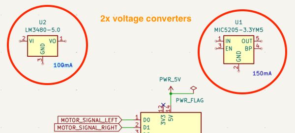
- 150 mA Low-Noise LDO Regulator converts max 16v to 3v3 for the ESP32S3
- LM3480 100-mA, SOT-23, Quasi Low-Dropout Linear Voltage Regulator converts max 30V to 5V for the RP2040
For now I just added them in my Kicad schema so I have a footprint to work with
Fixating electronics on the inside of the lid
Regarding fixating several electronic components / Navigation PCB on the inside of the lid Henk mentioned the use of double sided tape and inserts.
3D inserts
I watched this video and learned:
- temperature should be set to around 240 degrees Celsius
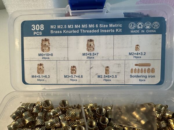
- use a square solder tip if possible (usually soldering tips are conical) because it will otherwise stuck to the nut you just inserted
- don't push them all the way in because they leave burn marks around them. Instead leave 1mm and turn it around and put it on a flat surface which will push it all the way in
- for inside holes you can use a flat bolt to push it in
Regarding the diameter of the holes in the 3D design they all refer to the specs from the supplier.
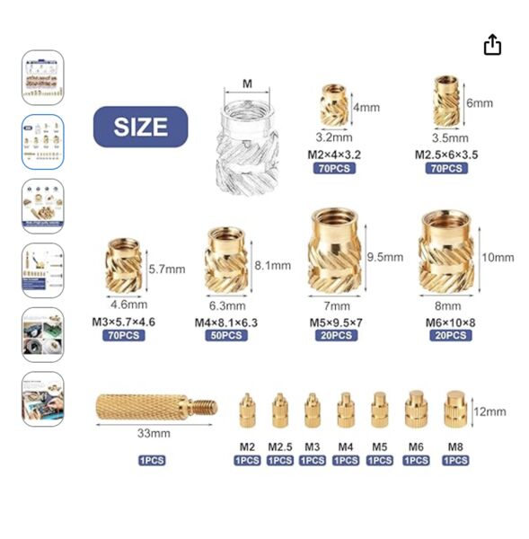
So in my case that would be a diameter of 3.2mm with a depth of 4mm when I'm using the M2
Anyway it looks promising.
When using the M2 bolts than I'm dealing with these specs
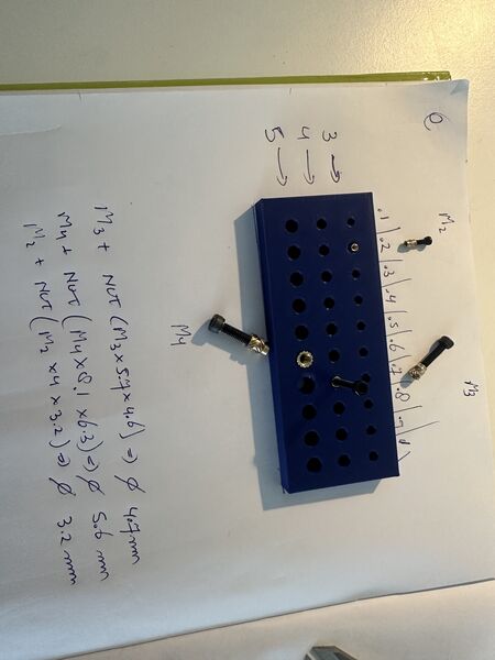
I therefore created a 3D printed block that contains a lot of different diameters.
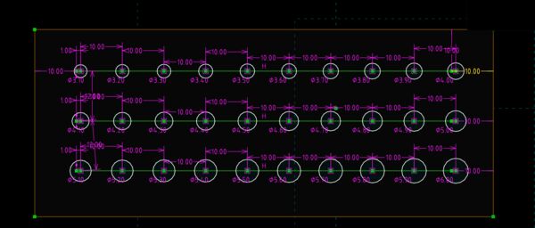
first row from the top starts with 3.1mm diameter; 2nd row with 4.1 and 3rd row with 5.1
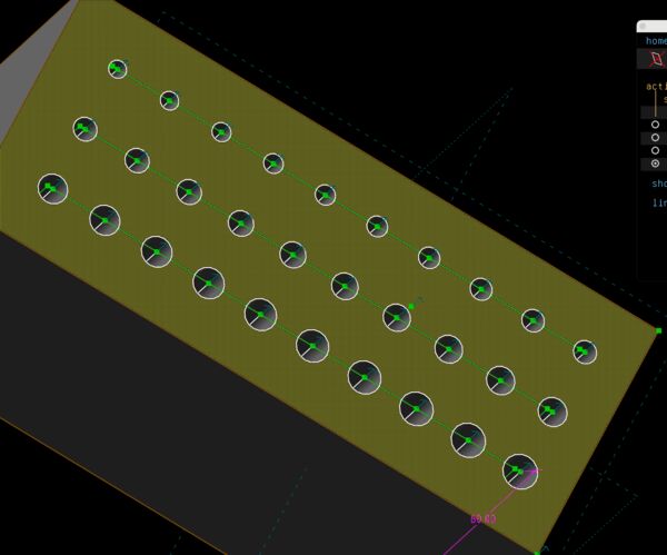
equal depth for all
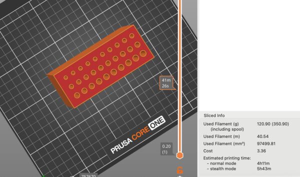
PrusaSlicer mentions 4hours????? Appearantly I made a mistake in my design using 60mm thickness instead of 6mm
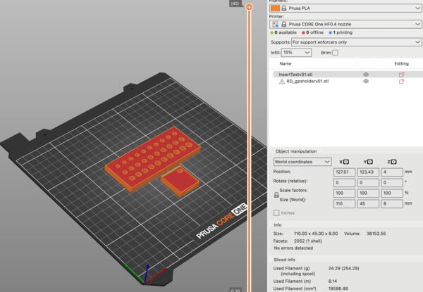
this will only take around 25 minutes
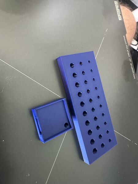
So as soon as I have the inserts I can test the right diameter for M2 and M3
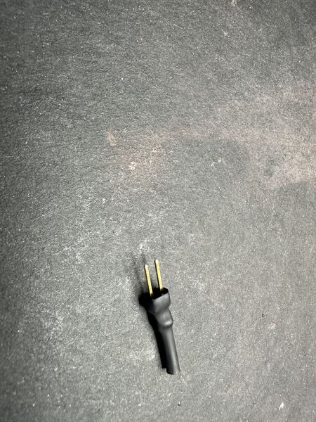
On/off switch
My idea of a general on/off switch is to use magenetic pogo pin. It will go through the lid. Part of it will be attached to the duck
Once it clicks, it can act as a switch
Intermediate reflection
Still a lot of stuff to do
I made a couple of decisions sofar:
- PETG looks nice but for the hull I'll use PLA (tougher and more smooth)
- (optional) Use PETG for the lid as it is more flexible and I can see a bit what's going on inside.
- Switch to 1 12v power source BUT use the current battery holder design
- Use a pogo pin as a general on/off switch (which is now more easy because of the one power source)
- Use
insertsto attach the lid to the hull - Use
insertsto attach electronic components to holders - Use doublde sided tape to attach the Navigation PCB and the holders to the lid
- Use the GPS GT-U7 GPS Module instead of that of Seeedstudio; it's flat and I can solder wires to it (and it worked last time)
Consequences:
- Design holders for the electronic components
- Experiment with
inserts/ diameters to see how I should design the space forinserts - Adjust design of the anchors in the hull
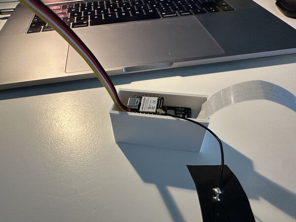
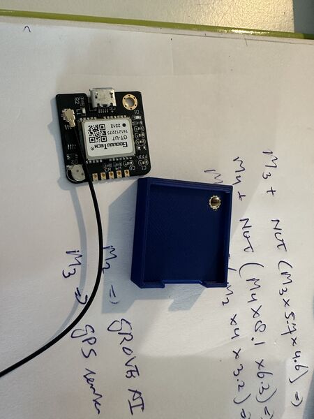
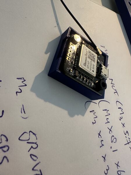
Holders for GPS
What I learned:
- enough as a holder for the brain
- use double sided tape to fixate the holder
- use bolts to fixate the chip itselfs
Holder for AI/brain
What I learned:
- enough as a holder for the brain
- use double sided tape to fixate the holder
- use bolts to fixate the chip itself
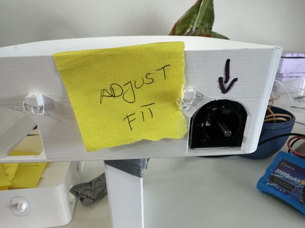
Motor and waterjet fixation
I'm still not happy with the way the waterjet is connected to the hull. And I don't want it to move forward or backward too much.
will be attached on the outside of the hull; has a nozzle as well
structure on the inside so the waterjet can't come inwards
took 20 minutes or so
and not too bad but needs to be longer at the bottom so that it can cover the whole area
When I tested it ... on the inside there was a lot of stress because the structure was just to near; so I added just 1mm more space and printed a small portion again to see.
still a bit too much on the outside
to tight; stressfull; force the bottom of the hull to bend
to save on my blue PLA I just print this one with PETG again
nice; fits like a glove
What I learned:
- new inner design for motors should be enough to keep them in place
- outer design of nozzle with holder should cover it
The lid
I still think it's too difficult to get the lid on the hull. The reason of course being that I take the shape of the hull and perform a boolean difference to get the base shape of the lid. I want to try to scale up the hull a bit to see if the contours of the lid on the inside will just be that looser. If that doesn't work then I can always do some sanding.
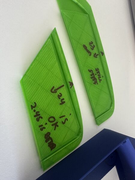
two pieces with just different scales; top was scaled 1.03 and the bottom one with 1.05
Both fit better put poses another problem of course (why didn't I think of that) ...
But that means I need to extend the hull again? No than I would end up in an endless loop
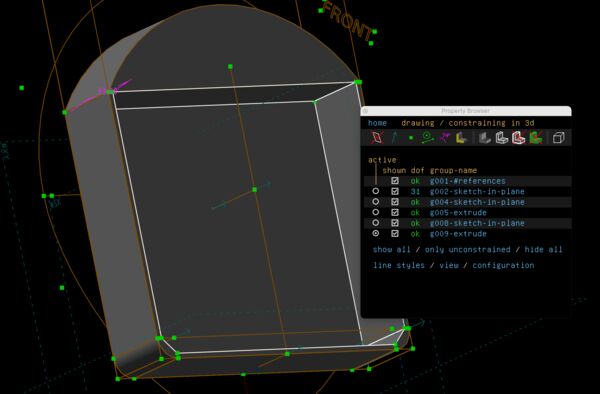
Next idea is to, whenever I have a new version of the hull (and when the outer rings has changed), to copy it as new version. In that version I will increase the wall thickens from 2.0mm to 2.45mm. That version is then imported into the lid version.
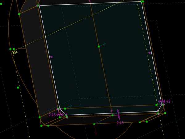
keep the outer wall the same but make the wall 2.45mm thick
still looks fine; same depth
use it with a boolean difference operator on the inside of the lid
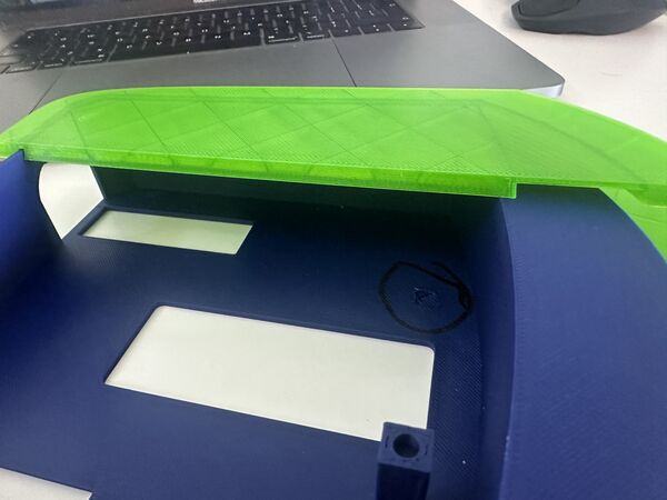
to really know I need 3 corners
much better fit
even better when just sanding it a bit on the inside
I learned:
- use the copy technique
- scale the inner wall to 2.45mm thick
- use that version to create the inside of the lid
Week 19
Converting 12V to 5V and 3V3 (continued)
Based on Henk's idea I'll convert 12V to 5V and 12V to 3V3 (for the ESP32S3) so that the RP2040 does not have to provide all juice to the GPS sensor and the ESP32S3.
Layout corresponds to the one I created inside the lid
Important: to include a switch like connector so that the pogo-pin can power on/off the whole system
The datasheet for the MIC5205-150mA-Low-Noise-LDO-Regulator shows this info
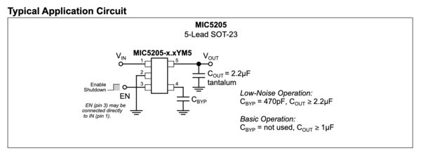
I can connect pin 1 and 3, I can skip pin 4 because of basic operation BUT I need a small capacitor on pin 5 of at least 1microF connected to ground
Leading to an updated schema
But I have problems with tracing the 12v-3v3 converter.
Error is that my rules prevent me from placing a trace in between
Now I need pin1 and pin3 because otherwise it won't do anything. I can use a wire etc but that's not prefered. So I tried to see what others did. I found Bowen who mentioned using a 3v3 - 1A converter. It has the same kind of shape as the 12v-5v converter with only 3 pins. And then I started to doubt ... why not just 1A as max ... The grove can be consume together with the ESP32S3 (wifi etc) .. it's a small change I can still make; and why not do the same for the 5V to the RP2040; just in case.
I looked at the lab inventory and found these 2; both can be found in Kicad as SOT223 family
So for both I have to add 2 capacitors
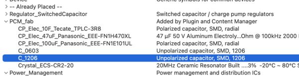
Looking in Kicad I find 2 types of footprint; no special mention of the ones I need. So I guess I just need either a C_1206 or C_0603.
I therefore measured the 10muF as 3.1mm long and 1.5mm wide. According to (for instance) this info I need a footprint that's equal to C_1206
It took a while but I finally managed to create a PCB that wasn't too big
Milling it with the MDX ...
first time it wasn't yet all the way through.
Henk suggested to use 0.007 inch instead of 0.004inch.
Second time it didn't go through again. This time Henk centered the bit on the middle of the area and now it was ok.
After cleaning up
Experimenting with inserts
my personal insert
after trying out 3 sorts of bolt
added one for the GPS board
Works fine however a bit tight
Used a M3 bolt to measure how high/low the inserts should be in the hull
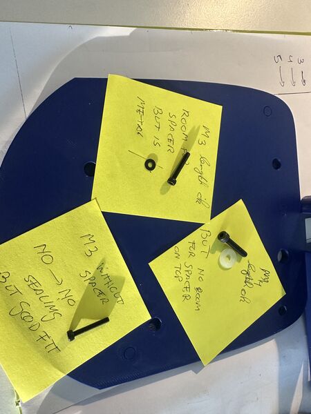
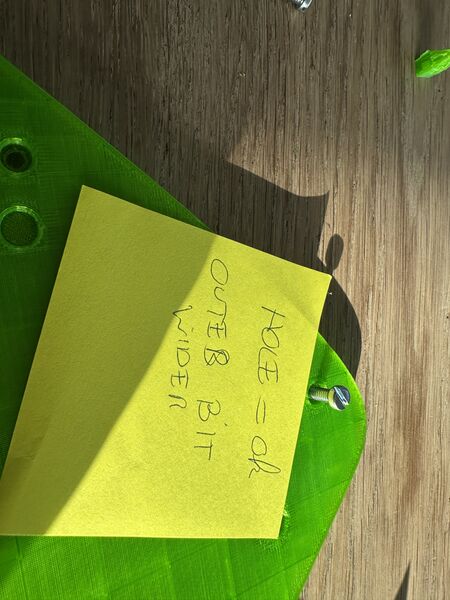
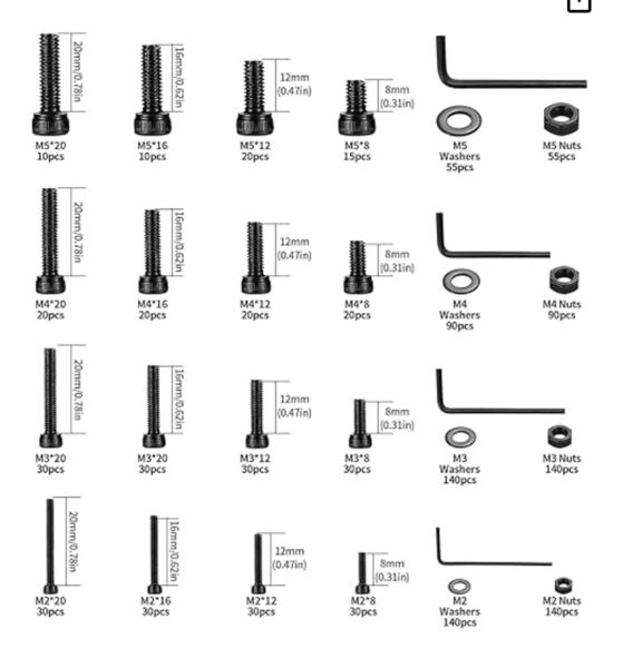
Testing the bolts with washers
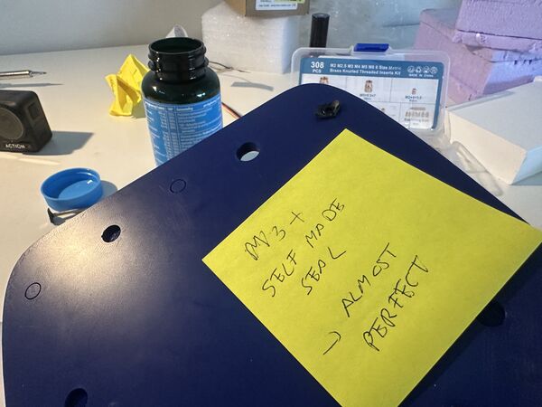
conclusion for now I'll use M3 bolts with the appropiate insert and a silicone washers
What I learned:
- heat up around 10-20 degrees more than the printing temperature (in my case PLA 170 so used 190 degrees)
- make sure there's room underneath the insert; because plastic has to go somewhere
- just insert until 1mm and push the remaining part with another tool or just press it on the table if possible. That way it won't go in too far
Soldering
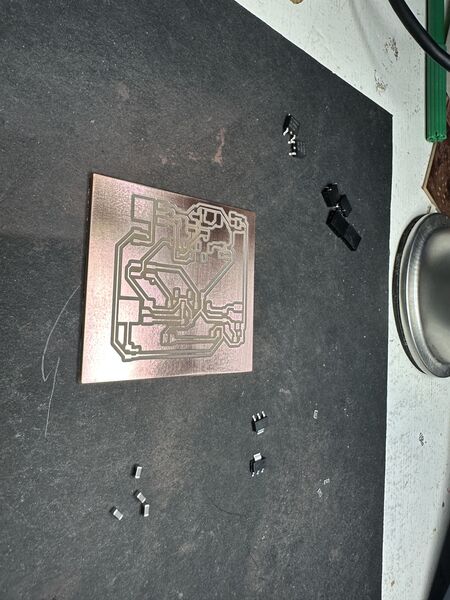
Most of the components I need; starting point
I used soldering and the heat gun
Appearantly my choice for the size of the footprint for the Schotkky was 0603 but the diode itself was way bigger than that. So I solved it like this.
All and all it took me 1.5 hours. Then I tested most of the traces and all looked ok.
Regarding the diode I could only think of the fact that the previous PCB were I used it, it was soldered on the trace so I didn't see it as a problem because I could fit is.
Power!!!!
First of all I made nice attachments for the 12v DC power supply and a self made on/off switch
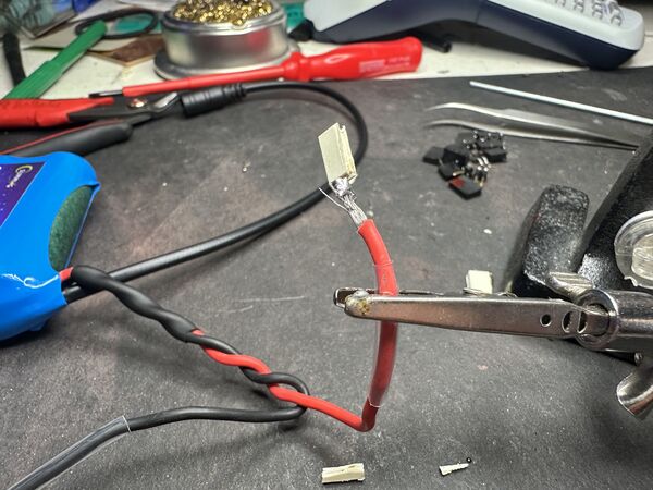
as designed made female connectors to go on the male headers on the PCB
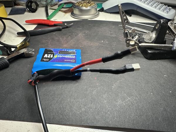
protecting it using shrink tube
self-made on/off switch
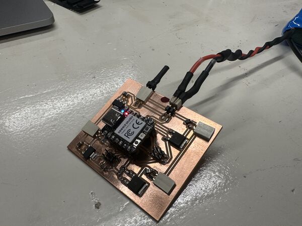
No I can safely turn on/off the PCB AND the RP2040 works!!!
Remark: eventually the on/off switch will be replaced by a pogo pin on the outside
Oh and I really like the heat gun
ESP32S3 power problems
Appearantly I tested until now powering the ESP32S3 using USB and that gave power to the underlying AI vision module as well. Now I misread and thought that the Grove wwould power the ESP32 but it doesn't.
Yes the PCB produces 3v3 for the Grove AI module which runs on 3v3
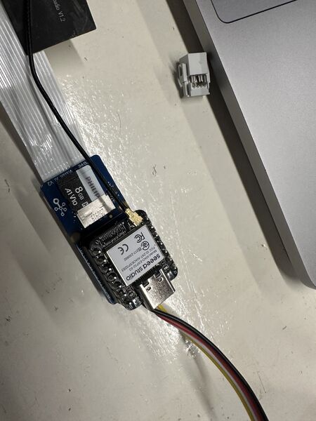
Adding the ESP32S3 on top of it does NOT turn the ESP32S3 on
powering the ESP32S3 with 5v from the RP2040 does work
and powering the grove with 5V? YES that works well
BUT .. when the Grove AI module is powered by 5v it does NOT provide 5v to the ESP32S3. That only happens when I power the Grove AI module using USB-C
so time for a small trick ... 5v from the RP2040 and ground from the grove cable. YES works
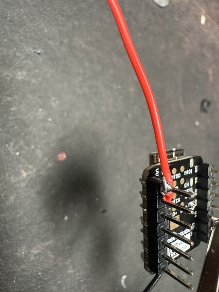
So I made this small wire directly soldered on the 5V pin of the ESP32S3
the 5v comes from the RP2040's 5v pin
then connected it and it worked
Remark: I also tried to solder 2 wires at the bottom of the ESP32S3 and power it with 3V3; that didn't work. It would blink briefly and then restart. It really needs 3v7.
Putting it together
Now with the power problem solved it was time for the finishing touches.
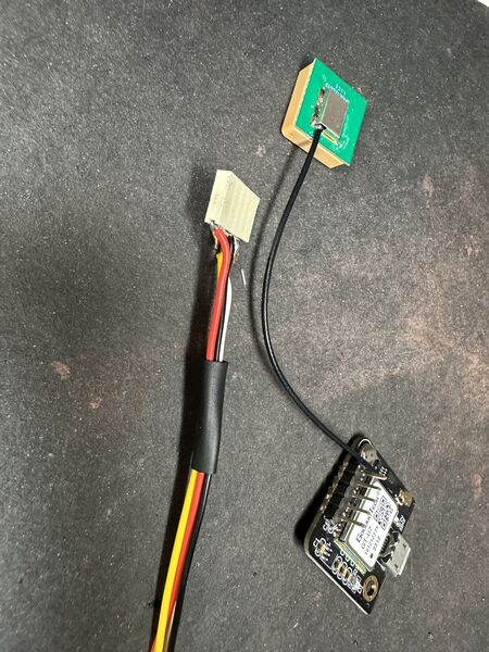
soldering the GPS module and made a cable
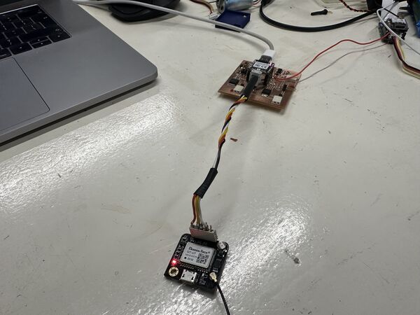
which worked
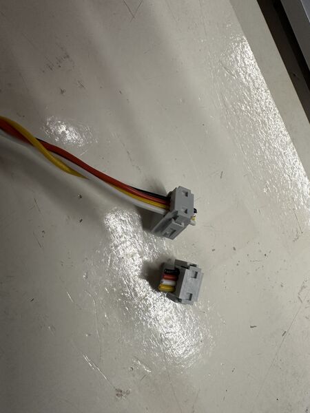
getting info was hard because I switched one cable
but the cable fix worked
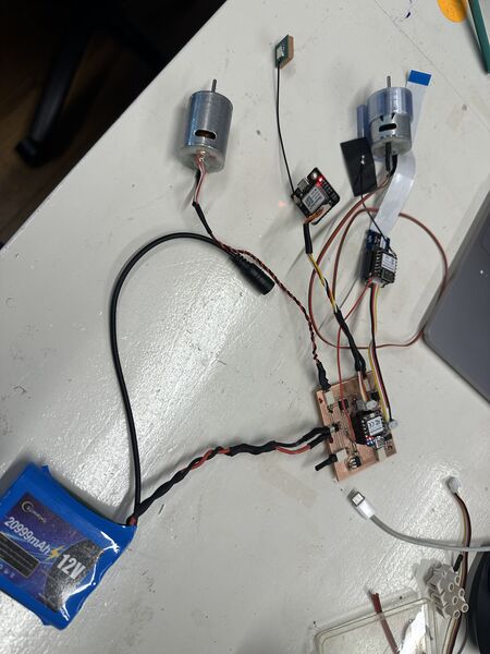
time to put it all at work at the same time
Everyting powered by the 12v battery; motors on for 60 seconds and 2 seconds off
Network issues
I was very happy with the result; until I notices that my network connection with the Wifi server dropped and reconnected again. Also weird messages like "your password is wrong" but when I hooked it up to a computer it wasn't???
Ok so yes there was one code issue. Appearantly in the code of the ESP32S3 I waited for the serial USB connection to come up which of course never happens when you are not using USB.
So at the end of the day I had a working PCB board but only the ESP32S3 just didn't get enough. Why? It was connected to the 5V of the RP2040 which got it's power from a voltage regulator that was maxed to 1A.
Back to hull design
I had some small fixes I wanted to make
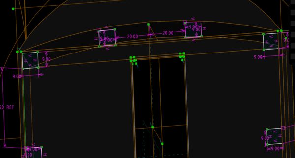
make enough room for the 4.75 diameter for the inserts
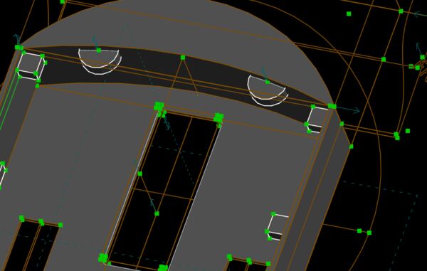
created 2 new placeholders at the front because I expect some water there
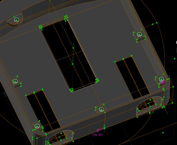
adding the holes for the inserts
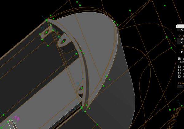
tweaking and tuning to take away material to make an edge at the front as well
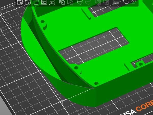
So looked good in SolveSpace but PrusaSlice showed some holes because there were intersecting edges
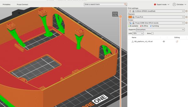
I could not get the new edge to work. I had problems with so called intersecting edges which I can usually get away with. But now I didn't know how to solve that. So I returned back to the original front. Main priority is getting my duck in the water and test it.
Back to the desing of the lid
On Friday morning, now that the hull was printed, I redesigned the lid
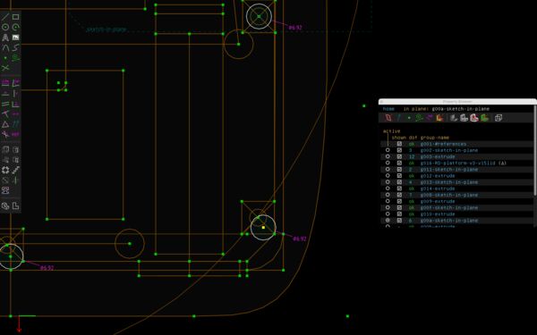
Need hole with a diameter of 4.7; as my printer does a tighter job I changed it to 4.75
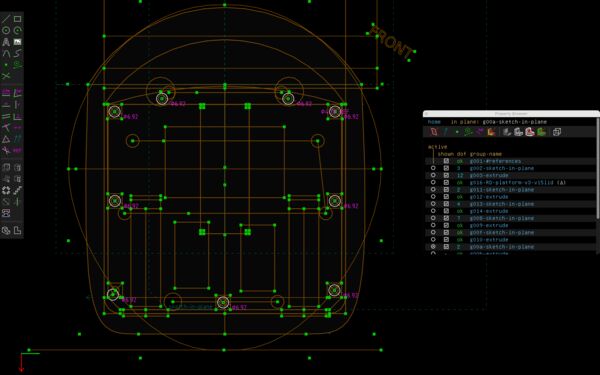
added more attachments point to make sure I can seal it
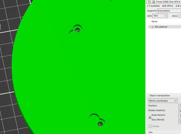
Looked good in Solvespace but PrusaSlicer should be the possible reality
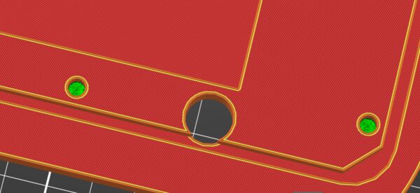
And this one
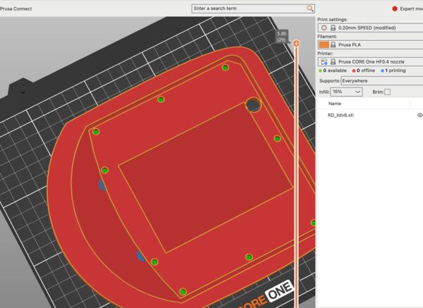
Finally I started to print this one
Waterproofing
At the end of Friday I took the results of my prints sofar.
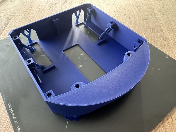
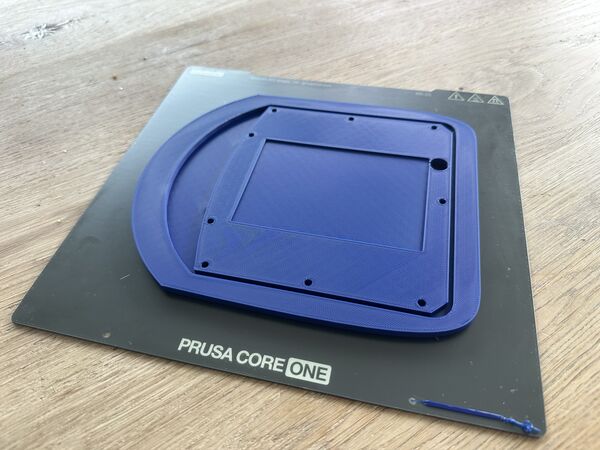
I sanded the lid until the fit was not too tight
Then I soaked both of them and the battery holder in Dichtol to make them water proof
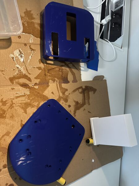
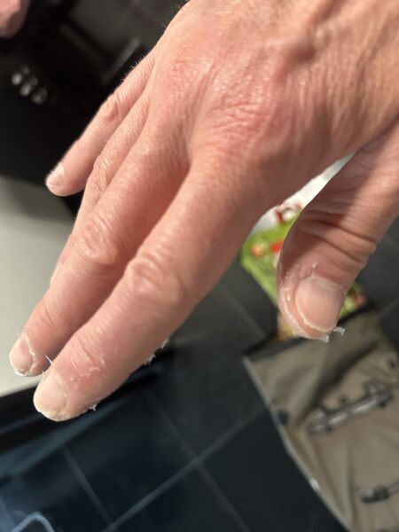
Next time I will wear gloves
The next morning I found it like this
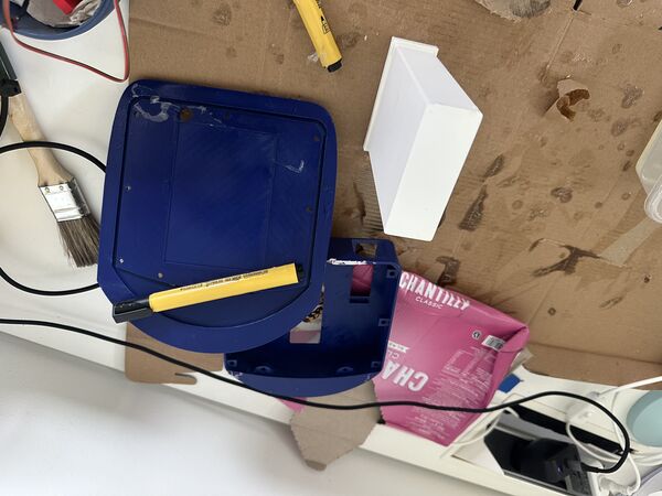
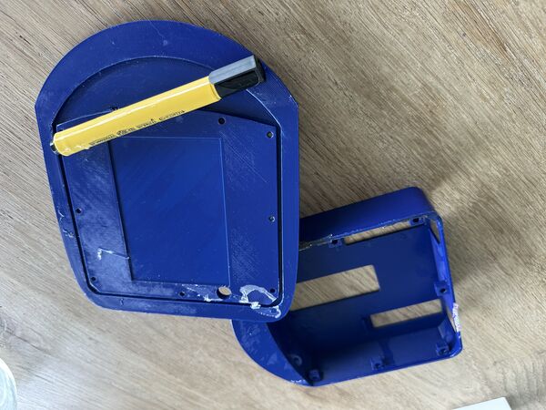
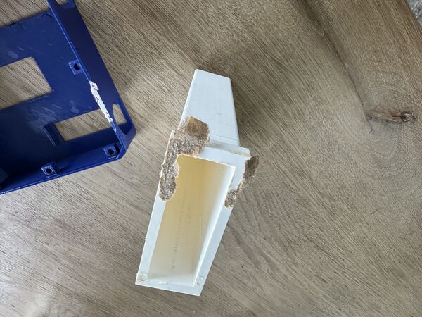
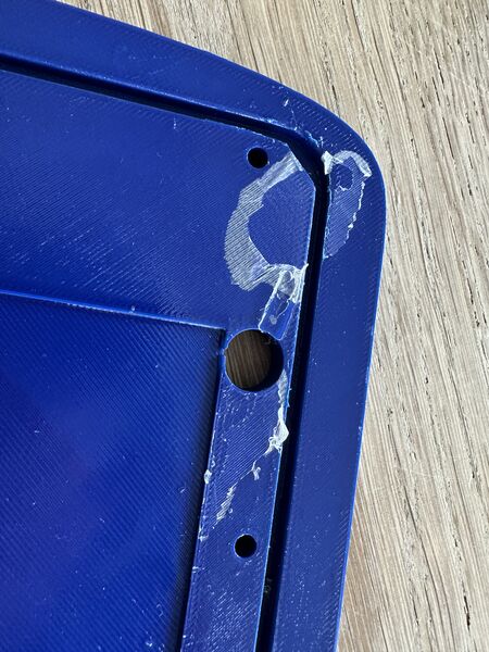
Another lesson learned is to NOT dry it on paper.
From power issue to possible shortcut
My main taks for today was to find out how to improve the power to the ESP32S3. My theory was that every Serial.println somehow caused an issue ... Henk didn't think so. So I just did some simple checks again:
First I powered the ESP32S3 via the USB of my laptop. Everything was fine and I could connect my phone to the Wifi network "RD3000". Then I just switched power source to the power bank. Same deal it worked.
Then I switched back to 12V battery using the PCB. Appearantly it all worked. Huh? Was there no problem anymore? Nope ..look again. My phone was not able to keep the connection and reloading the home page. Also the ESP32S3 showed it's startup red led once in a time. Which would explain the network dropping out; it was rebooting probably because of lack of power.
Note
According to the website of Seeedstudio the ESP32S3 itself draws around 40mA, and when using Wifi around 100mA.
Ok but how much was it drawing on current right now. So I played around with the multi-meter and found that both voltage regulators worked fine; showed 3v3 and 5v. But how about that current? Well long story short at one moment I put 12V directly on the 5V pin of the RP2040 and the ESP32S3 which was, at that time, connected to the RP2040.
I thought that everything was basically dead ...
So I retested all components like the Grove AI module, the ESP32S# and the RP2040 using direct connection with my laptop via USB. They all still worked. Ok!
Then I saw why my PCB didn't work anymore ... I had burned through the GND trace. I fixed it with a small blak wire.
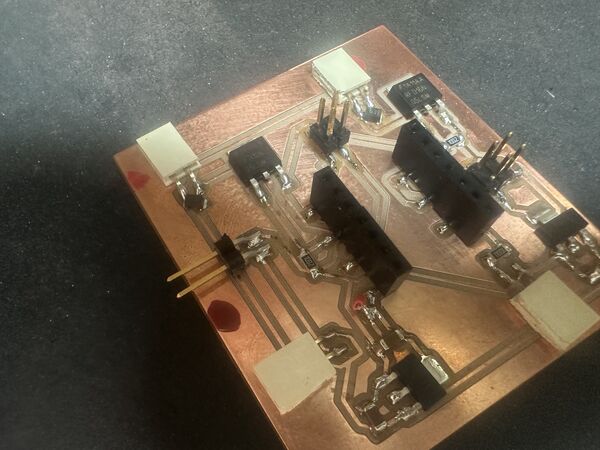
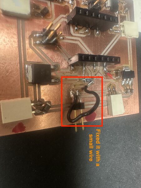
Then retested my PCB which still worked also. Then reconnected the RP2040, the GPS and the motors. It all worked!!!
Note
The idea is simple ... your multimeter has to become part of the circuit in order to measure current. By doing this the wrong way ... well .. bad idea. So I found this video which told me stuff that I kind of knew. Difficult part was being part of the circuit.
I finally hooked up a motor and used that to make the multimeter part of the circuit. It showed 0.7A of currrent being drawn from the battery at 12V.
So with all that back to my problem from this morning ...
I still want to power the esp32s3 seperately ...And in my search found this guy who created a mini-drone using a battery powered ESP32S3. And there it is, a battery of 3v7 ... So that is what I need not the 3v3.
For now I stick to the solution of using the power bank to power the ESP32S3 and the 12V battery to power the rest.
Back to communication
So more in the afternoon I had the following setup ...
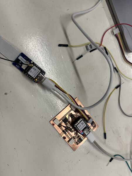
By powering both the ESP32S3 and the RP2040 via USB I could activate the serial monitor and see that the RP2040 actually did get messages from the ESP32S3 via the cable.
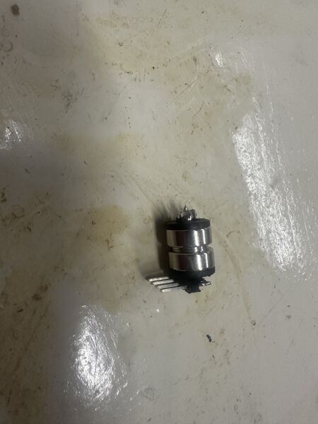
At the end I did manage to solder at least a part on the pogo pin as it has to go inside of the hull
Back to the motorholders
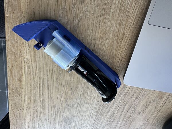
the last version I have; try to fit it with the latest hull design
I updated the design of the motorholders slightly.
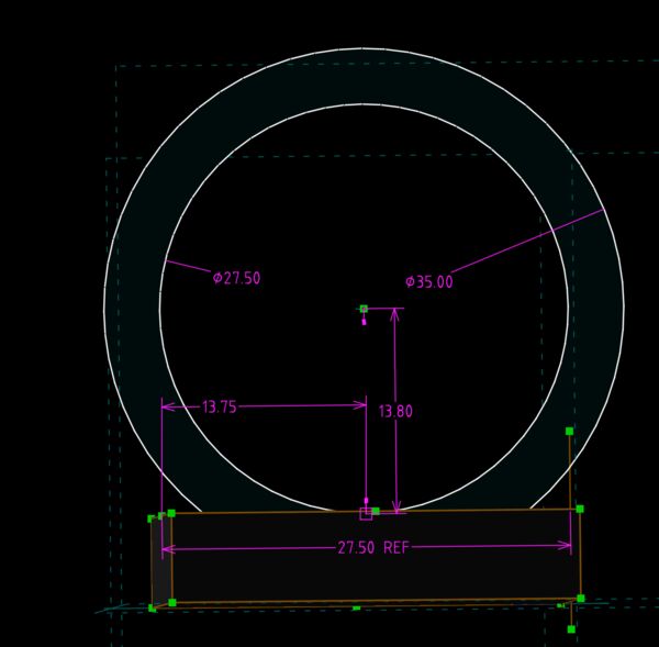
Increased diameter of the outer ring so that it's more part of the base/ foundation. This should increase it's strength when then motors spins. Also increased the thickness of the base so that I can fixate the base to the wall instead of the base of the plaform
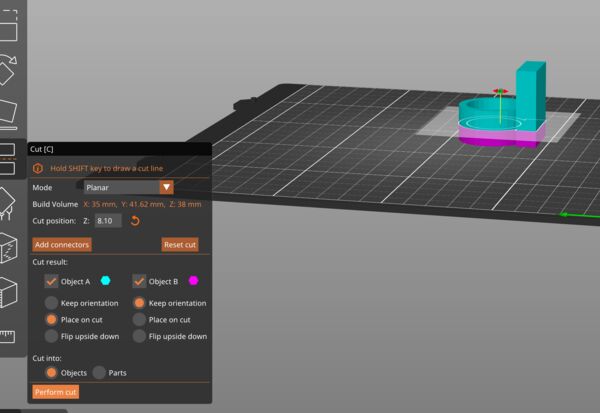
To test I'll just take a portion
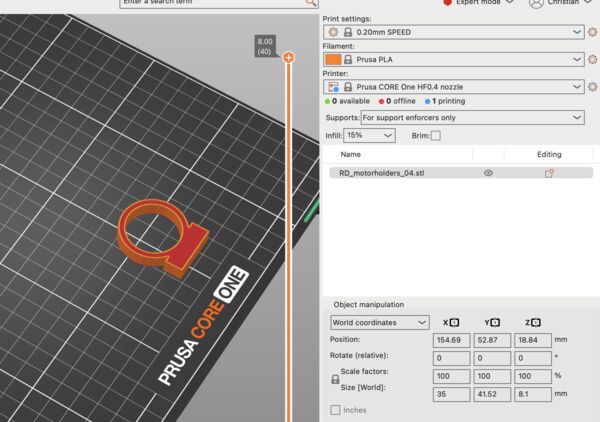
So that if I'm wrong I spare some filament and time waiting for it to finish
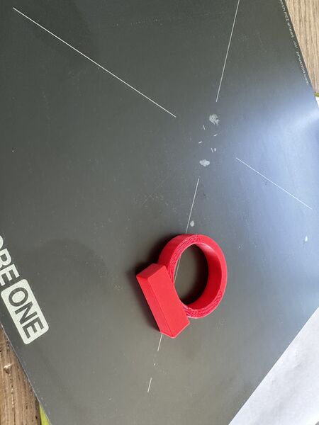
Came out fine but it appeared to be too wide; it would lift the motor's axis and it would not touch the inner hull
Then increased the base just a bit and reduced the diameter to it's original size
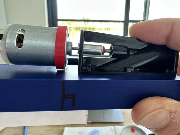
But now at the base of the axis there is still some room
So added another 1mm and ...
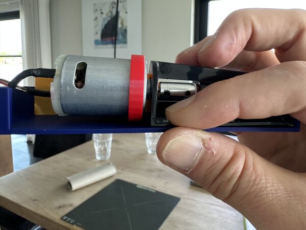
that looks perfect; but just needed a small addition of 0.5mm
Based on that I printed the final version twice
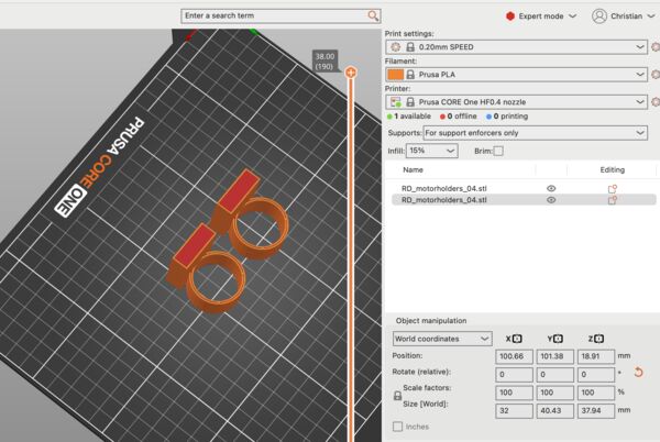
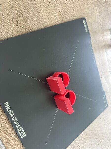
Back to the nozzles
Actually nothing to do here but print them in the same red color
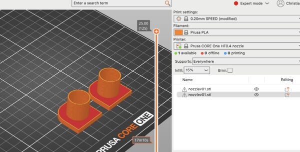
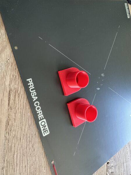
System integration
I want to show all the components that are needed and how they fit together ... So I got all the materials that I need and laid them out
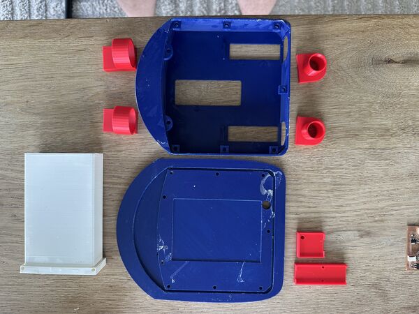
3D printed material
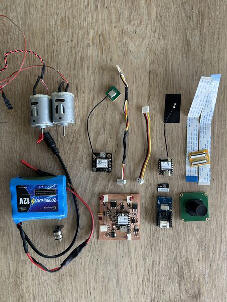
electronics
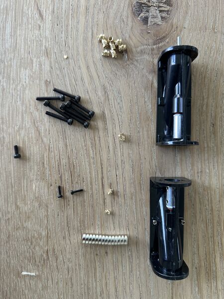
waterjets, insert and bolts
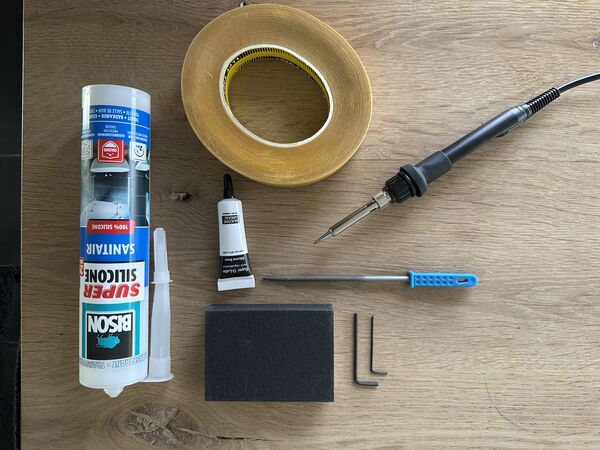
tools/ other
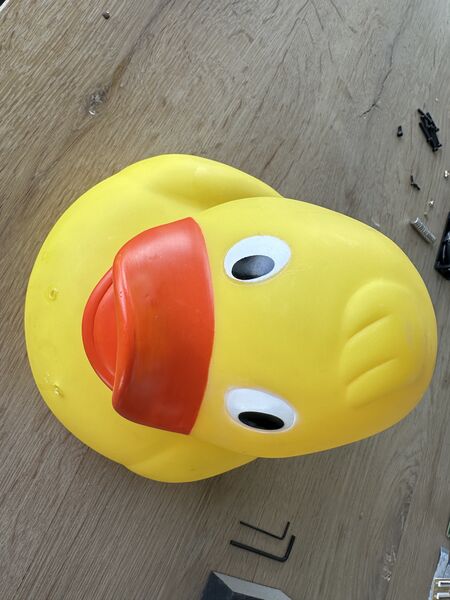
and finally the/a duck itself
Then tried to pre-assemble everything and found some minor issues
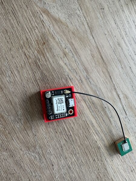
I discovered earlier that the GPS holder was ok but that the insert needs to move just a bit to the left.
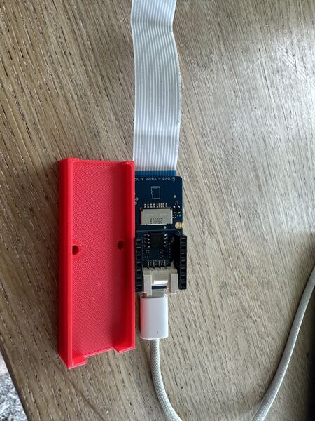
And to let the flow of cables run smoothly I decided to adjust the holder for the Grove AI / brain part.
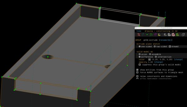
Back to SolveSpace
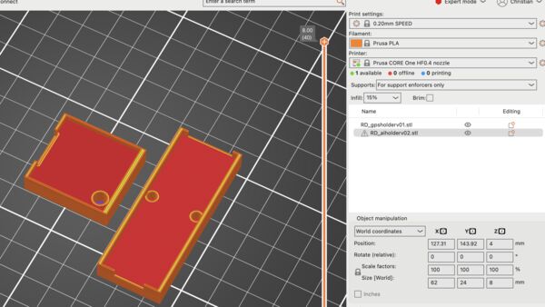
Print both of them again
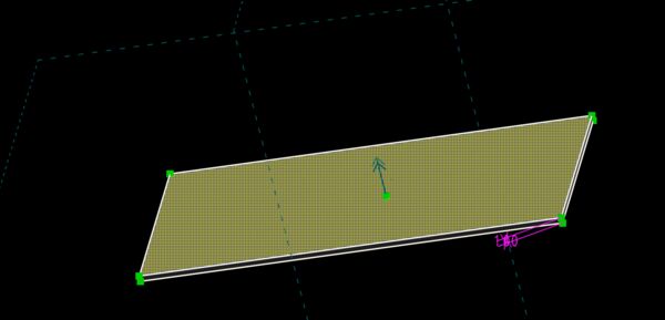
Including a new part to fill up the inside of the lid
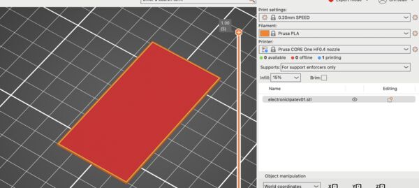
Just a small plate of 1mm thick
Assembly preparation
Time to apply silicone to the insight if the lid and attach the battery holder to the hull
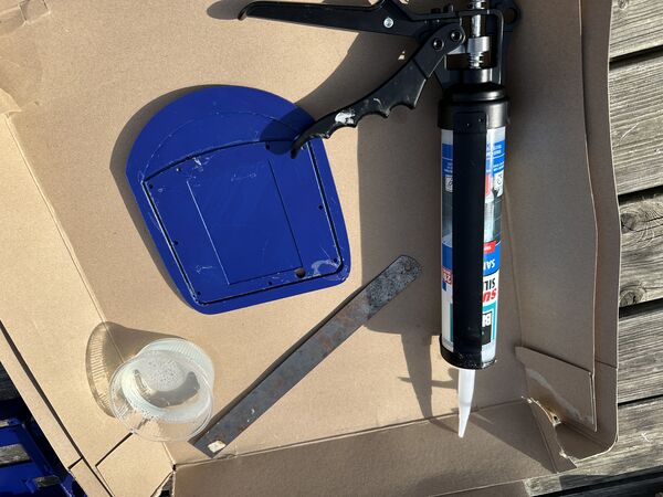
Using fast drying transparent Acryl silicone (2hr to make it waterproof; 24h to make it stress proof)
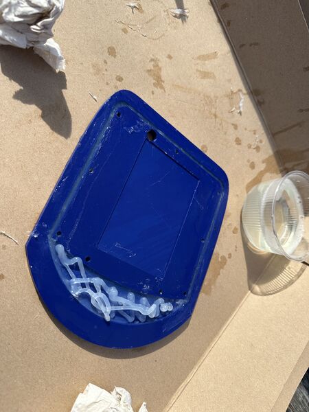
there is no neat way to do the front; just add and adjust with my fingers
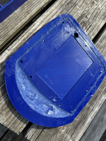
It looks ugly but I hope it works
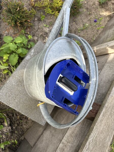
Use the wait of the powerbank to keep it in place while drying
I learned from this that it would have been better to fixate the battery holder at the end as it will be more difficult to work on the hull.
Next morning I decided to fixate the water jet using fast drying glue or glue pistol. The main reason is speed! I want to put the duck in the water as fast as possible. I can always apply extra sealing with silicon once it's fixated.
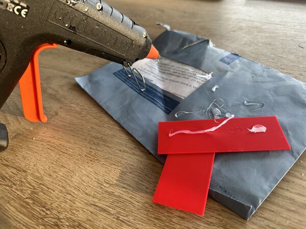
Showed me that it's fast, sticky and, if needed, I can get it off afterwards
So I laid down the warterjets and, assuming that they could not move anymore, found that it was almost impossible to add the motors later. This means that I'll have to pre-assemble the whole waterjet-motor-motorholder at once. And it also means that my idea of fixating the motorholder with tape at the back doesn't work; there's no room afterwards.
Also when position the base to the side, if not done right, the outer ring is still to narrow so it will weigh on the motors axis and prevent a smooth operation
On top of that, the base almost touches the inside of the lid; needs to be smaller
But I also noticed/ remembered that the waterjets can be fixated using small bolts
This would be nicer as I can attach more strongly and detach if needed easier
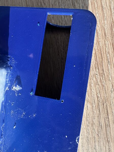
I therefore took a 1mm bit, scratch the surface and drilled the hole
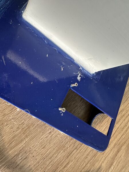
That could actually work
Ok then ... now let's see how it all fits together. But then I found some serious issues because of the fact that, for now, the electronic components will not fit at all now because I still need the powerbank; there's simply put not enough space.
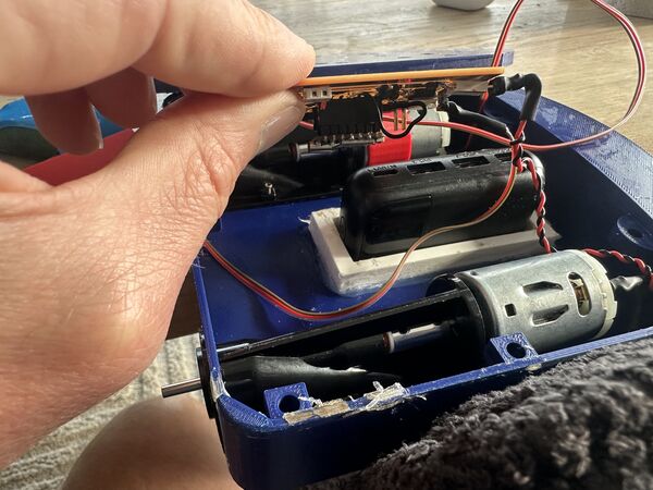
I did not plan for this; that's why I wanted to get rid of the powerbank and use a 12V battery
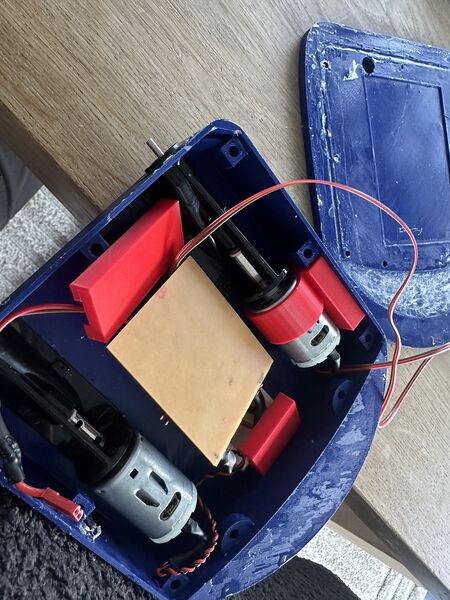
This was the idea, no power bank then it fits
Other smaller adjustments I need:
- the wiring in general needs to be more flexible so it can easily be tucked away
- the holder for the AI needs be reduces in length; just use the bare minimum space I need
- the male connectors to the motors should be in a 90 degree angle; now they have to be bend
Adjustments to be made:
- extend the outer circle of the motor holder with 1mm
- reduce the footprint of the base of the motorholder
- at the time use some glue at the top of the base to fixate it
- use small bolts that go trough the hull to attach the waterjets
- then use silicone to close any leaks
Note
The main reason for the powerbank to be there is that I need 5v for the ESP32S2. I redesigned to use only the 12V battery which would give me more space.
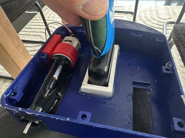
It can't put the 12V on top because then I can't have a USB-C cable from the power ban
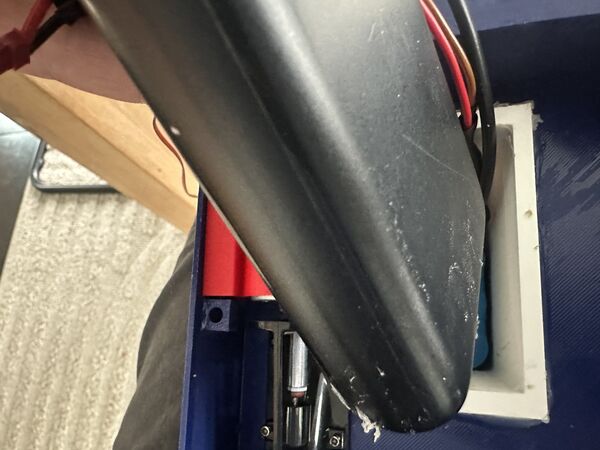
And vice versa
Besides that ... enlarging the batteryholder does not fit my 3d printer
So nothing to integrate yet ... back to printing first = small adjustment. I therefore started a new print containing:
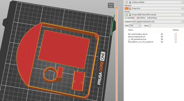
- newer version of the electronic plate
- newer version of the motorholder
- newer version of the Grove AI holder
- special version of the hull to later test the lid
While printing the 3D printer made a lot of noise. I thought it were the belts or something but during larger movements the noise was gone. So I looked at what it was doing but I didn't see any filament coming out. Jaiks ...it appeared that my filament was entangled at the side
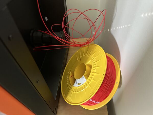
Next time check this before printing
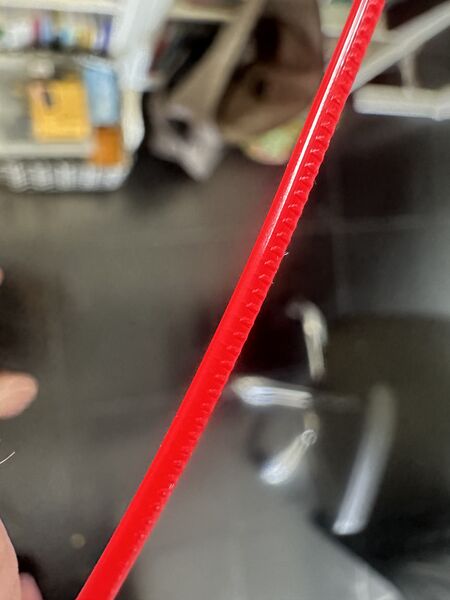
Marks from the extruder
The results
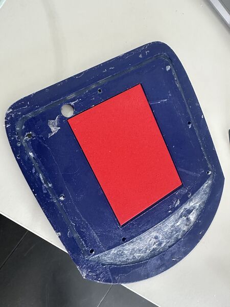
Fits like a glove
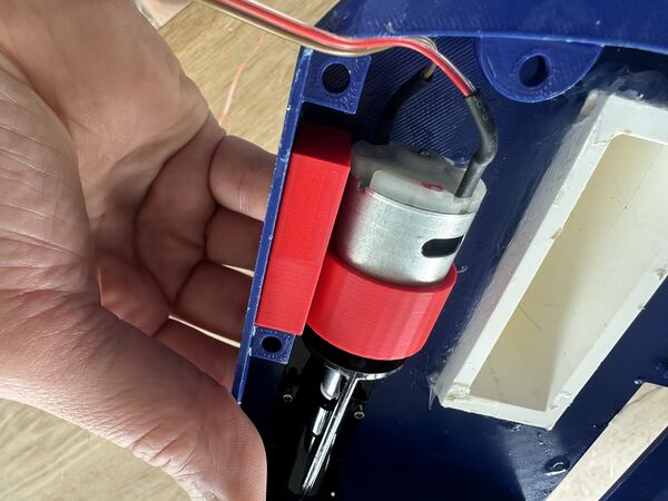
Perfect now
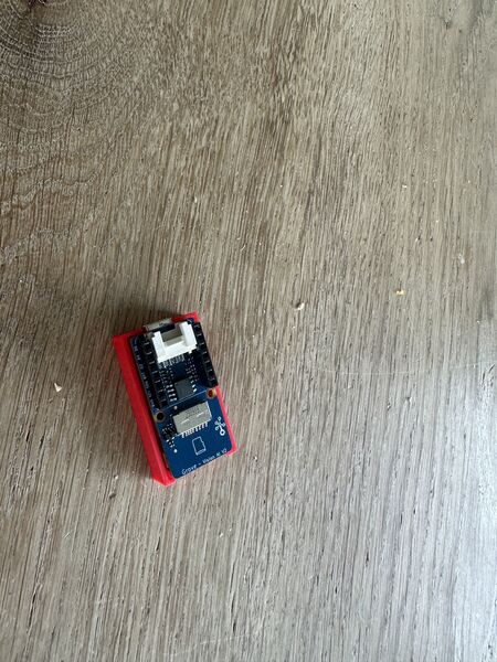
Yes also ok now
Coding
Besides making the duck float, it needs software.
GPS
I remembered that there is a library to interpret NMEA codes = what is spit out by the GPS sensor. Searching in Google for arduino library gps gives me links to:
So TinyGPSPlus runs on all types of Arduino boards and claims to be lightweight. It also claims
Like its predecessor, TinyGPS, this library provides compact and easy-to-use methods for extracting position, date, time, altitude, speed, and course from consumer GPS devices. However, TinyGPSPlus’s programmer interface is considerably simpler to use than TinyGPS, and the new library can extract arbitrary data from any of the myriad NMEA sentences out there, even proprietary ones.
When I look for it in the library manager I also see other variants like TinyGPS which is now in it's 13th release. TinyGPSPlus is in its 1st release. Looking at the example code TinGPS should give be LATITUDE and LONGITUDE. And it also gives me speed and course; stuff that I need. Also NeoGPS looks promising as a light weight variant with a lot functionality.
TinyGPS latest update was 7 years ago; TinyGPSPlus was 2 years ago. So in that case I prefer TinyGPSPlus for now.
Looking into an example called KitchenSink I like this piece of code
static const double LONDON_LAT = 51.508131, LONDON_LON = -0.128002;
double distanceToLondon =
TinyGPSPlus::distanceBetween(
    gps.location.lat(),
    gps.location.lng(),
    LONDON_LAT,
    LONDON_LON);
double courseToLondon =
TinyGPSPlus::courseTo(
    gps.location.lat(),
    gps.location.lng(),
    LONDON_LAT,
    LONDON_LON);
This suggests I can also calculate the course to a new destination (not being London of course).
Tank steering
Well the word tank is something I saw earlier on. In fact steering with 2 waterjet is in fact the same as steering a tank. I make some assumptions:
- there's a general speed settting (none, silent, low, medium, fast, max)
- using frequency of 20Khz and 8-bit resolution (this is from earlier experience) to use PWM
- from experience ... both motors start to turn when a value of around 30 is set so the actual range is [30,255]
- this means:
- 0 = stop
- 30 = silent
- 60 = low
- 120 = medium
- 180 = fast
- 255 = max
- straight ahead means both motors get the same speed setting
- if the duck has to go left it means reduced power on the left motor and vice versa
Scenario's:
- duck is set to fast and has to go left --> left/right motor = 120/180
- duck is set to low and has to go right --> left/right motor = 60/30
- duck is set to silent and has to left --> left/right motor = 0/30
Importantly ... whatever the power on a motor it has to increased or decreased gradually. This will be easier on the structure/ platform/ hull. The electronics are protected by a diode.
Back to converting 12V to 5V via USB-C
The assembly pre-test made me aware that I really need to get rid of the powerbank; I can't use it; not even for aa concept unless I want to redesign the hull ... Nope! Idea stays the same. By powering the ESP32S3 with 5v via a USB-C connection it will a) run a smooth Wifi connection and b) will power the Grove AI module as well.
At our FabLab I found a very small board that has a USB-C output and 12 through-hole pins.
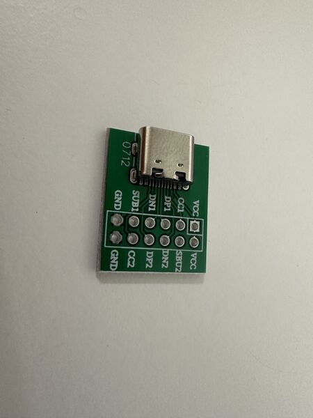
Lot of new abbreviations here like CC1, SUB1, etc
My guess is that it's a standard inventory thingie .. But I could only find something from AdaFruits in the list that looks similar. Reading the related datsasheet it points to a more general datasheet about USB-C and its terminology.
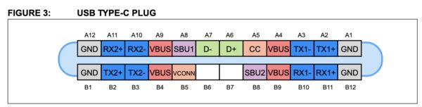
The USB Type-C connector has 24 pins. Because of its reversibility, the pins are arranged in a mirrored configuration. There are a total of 6 differential pairs in a full-featured cable assembly.
What I understand from this:
- The CC1 and CC2 pins are critical for basic USB Type-C operation. They deal with detection of cable attachment and removal, orientation detection, basic USB Type-C current capability advertisement (all communication regarding power delivery occurs over CC wire)
- The SBU wires are lower speed signal wires that is allocated for
Alternate Modeuse only (these are the SUB1 and SUB2 on my board) - D+/D- are meant for USB2.0 only
- I need to connect both CC1 and CC2 so that the ESP32S3 will get power however the cable is flipped
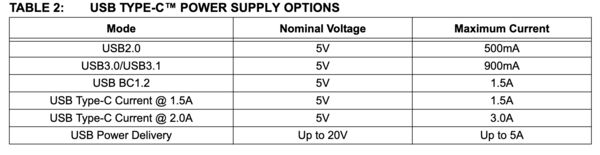
Using a basic setup using USB2.0 it will support 5v/500mA max which should be enough for the ESP32S3 (as the Grove module get's its own 3v3)
Another good article. This article also makes clear that, regarding the C1/C2 pins I have to be carefull. Because I can act as a power source (= advertiser) or a device that draws power. As I'm a provider I need to use 56kOhm resistors. This is also acknowlegded by this article.
So to summarize:
- create a small PCB that uses a voltage regulator to convert 12V to 5v (using the same one with a max current of 1A)
- Connect the GND of the USB-C breakoutt board to the GND of my PCB
- Connect the 5v output from the voltage regulator to the
VCCon the USB-C breakoutt board - Both CC1 and CC2 need to be connected to 5V as well BUT in between each there needs to be a 56kOhm resistor
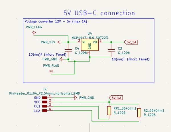
This means I have to make a split of my 12v source or solder it on the existing PCB
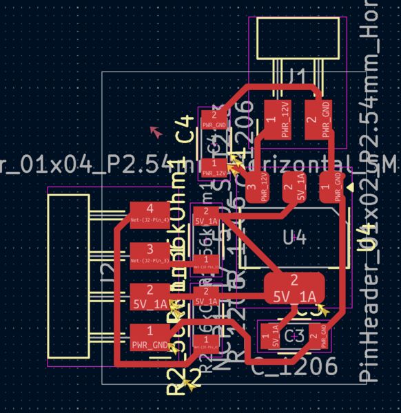
PCB 1.9cm x 1.6cm .. idea is to not use the male headers buut solder wires directly on them and then onto the USB-C breakout board
The next day I changed it a bit. My idea is that the 12V power source will directly connect to this PCB which well then be hooked up to the other PCB (throughput). That way I can basically keep the power and this converter inside the batteryholder.
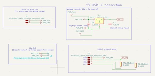
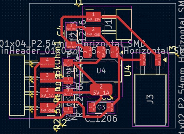
I took 4 times to mill it .. using increased cut depth settings starting at 0.004 all the way up to 0.008inches
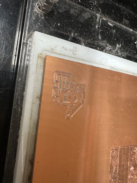
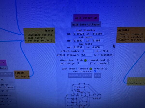
Used a cut depth of 0.008inches even and did that twice
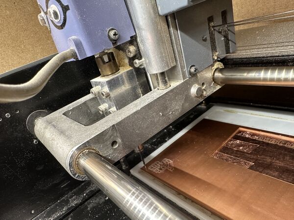
Getting somewhere
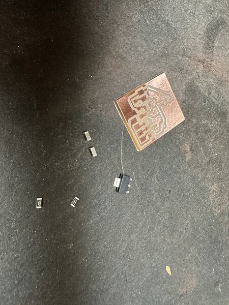
Yes I did remove last pieces by hand but it's now ok
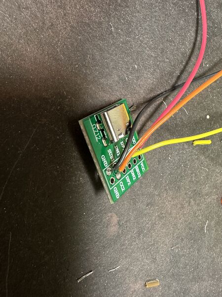
Then soldering the USB-C brake board
Note
My PCB required 56kOhm wich I thought we had in our Fablab. However we had 49.9kOhm. So I decided to first go for this value. In the datasheet of USB it says that there's an amount of tolerance.
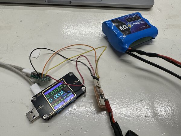
Luckily it worked right away
Then connected it to the ESP32S3 which was also very happy. Nice
Back to waterproofing the lid - hull connection
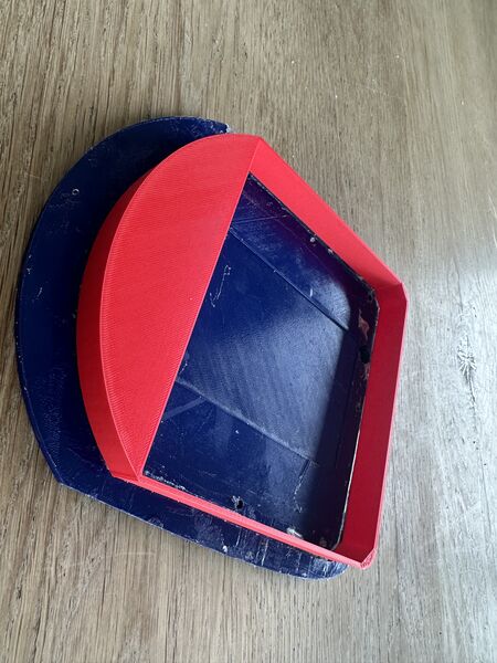
Although the print succeeded it does bring forward another problem
I tested the sealing of the lid by pressing on it very hard; it leaves too many gaps; this is not going to work; ships ...
However ... I wasn't paying enough attention
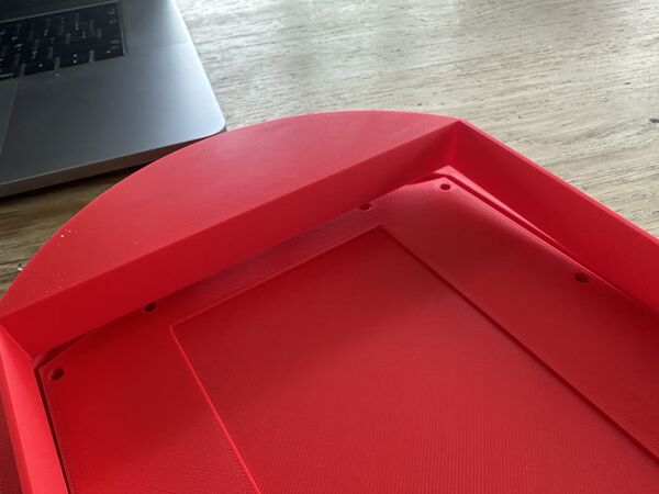
I took the wrong part of the hull to test it ... so yeah that's why it doesn't fit
Anyway ... still need some solution to keep the water out from the top. I talked with my son about it and he mentioned elastic; etc.. So the next morning I just starting doing some small experiments
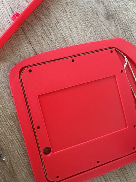
thin rope
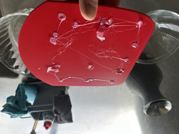
seal all the other hole first
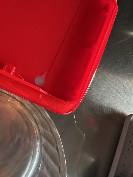
Took around 1.5 hours before it came out
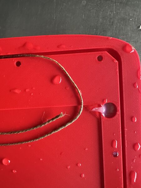
So yeah it holdes the water out until it's soaked
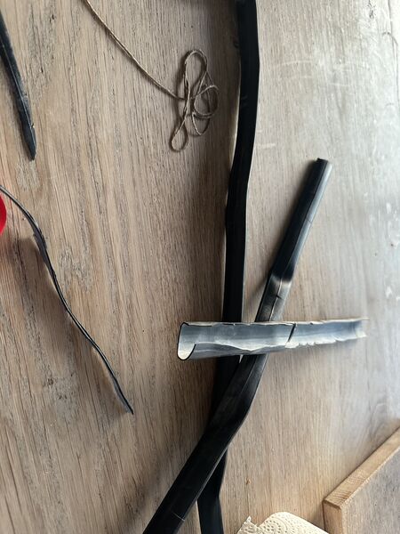
what about the inner tube from a racing bike?
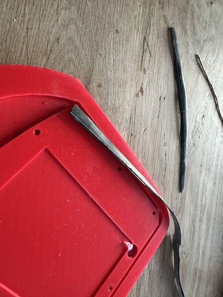
Difficult to cut small pieces and it was too thick
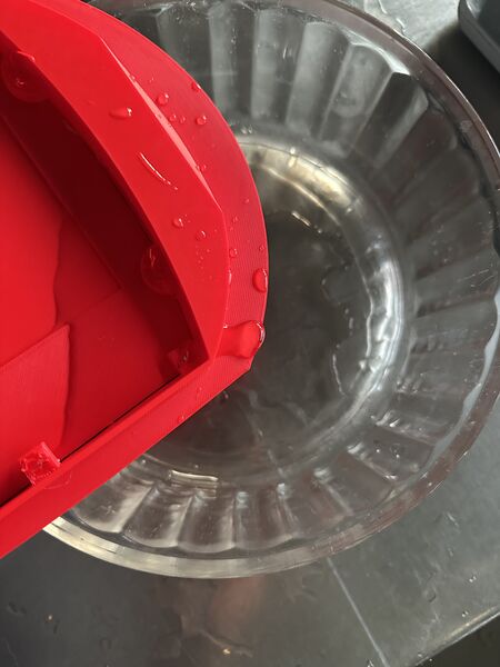
Water came out very fast
Of course rubber will work but then I need to change the design of the hull; make the space between the lid and the hull wider; cut the rubber in thinner pieces; etc... No tools and time for that. Onto vaseline.
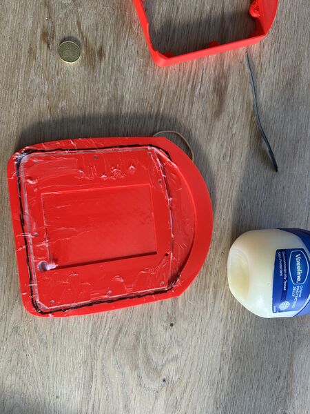
Used my finger to put the vaseline in the gaps
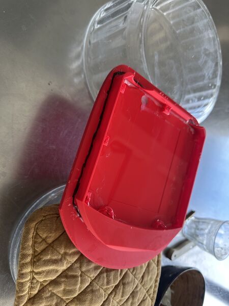
Same setup as with the rope
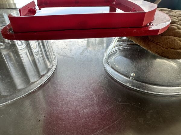
Still no water coming out after a longer time then the rope
Yes vaseline it is for now. Is this a permanent solution? No. I would like to make a mold and use a cast of silicone to make a very thin ring but that's on the options list for now.
Testing GPS
I included the TinyGPSPlus library and tested my GPS sensor ...
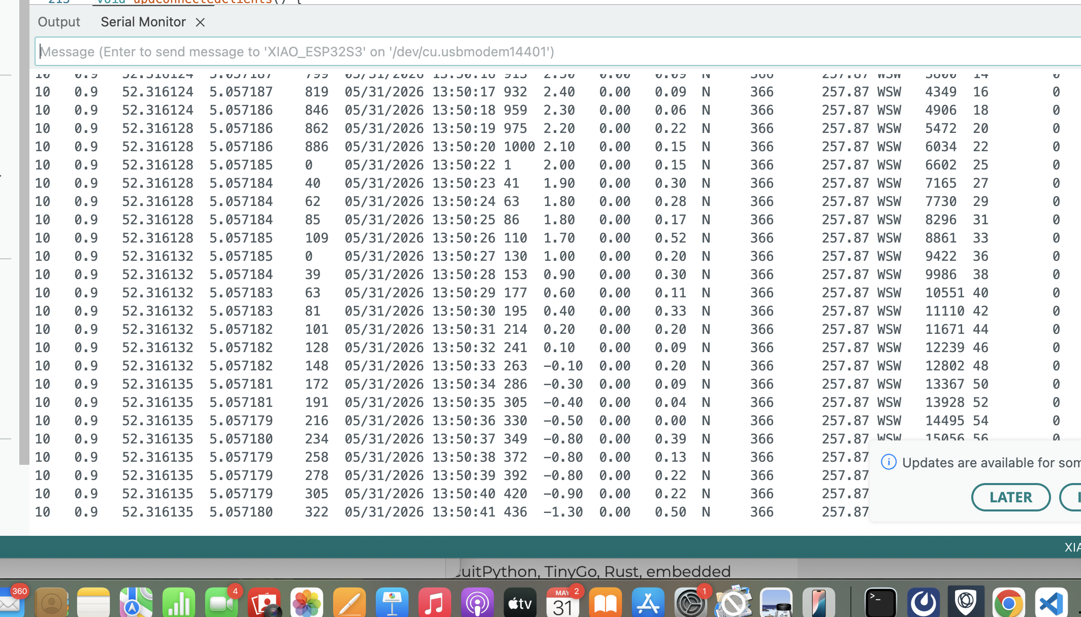
I changed the code a bit and went on the water with a boat and tested it. That at least was fun to do and it showed me that it can work.
Making the stand
My idea is to make a stand to display my duck but also make sure it doesn't fall over. There will be a base around the batteryholder and in front a contour of the duck with the name engraved.
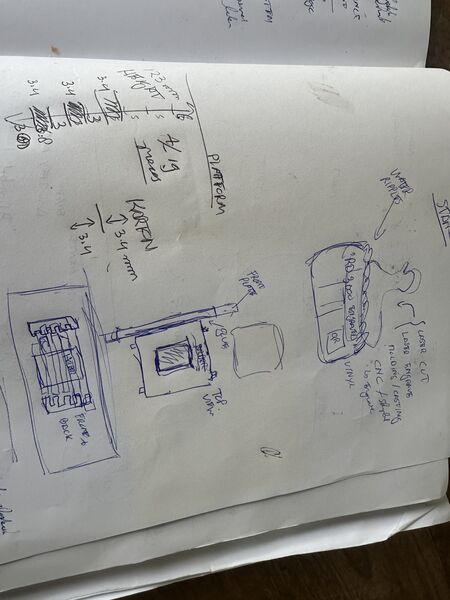
The base is not a problem as I can use Solvespace to export it as 2D plain SVG; this is what I need in LightBurn what we're using to control the CO2 laser and yes I need the laser to cut it from carton. I have a lot of scans from the duck so I choose a side view. The trick is to convert it to a SVG file with a contour not just the image.
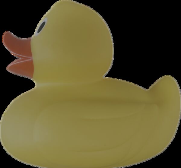
step 1 was a trick to use my iPhone to make a sticker out of it; just the duck
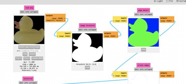
then to use MODSPROJECT.ORG to use it's image tools to create the SVG ... however that didn't work
Remark: I used this conversion tool from Shutterstock to create a contour SVG from my duck
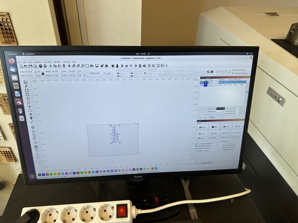
LightBurn to set the speed for the cuts to 100mm/s with a min power of 20% and a max power of 30% (thanks Remco for refreshing my memory)
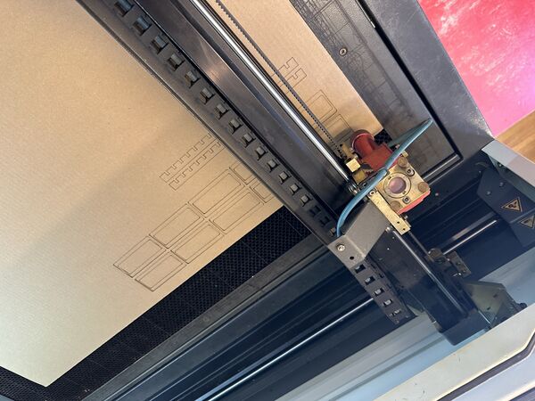
Quick and easy
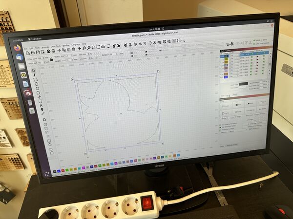
Duck has several contours of which I only activated the outer one. I used speed 160mm/s with the same power settings.
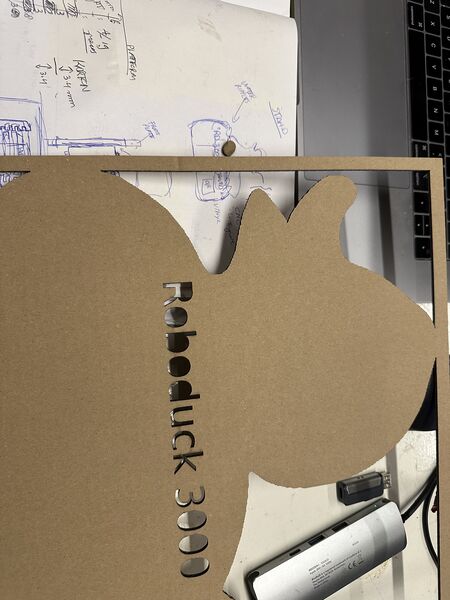
Nice .. although the letters should have been engraved not cut
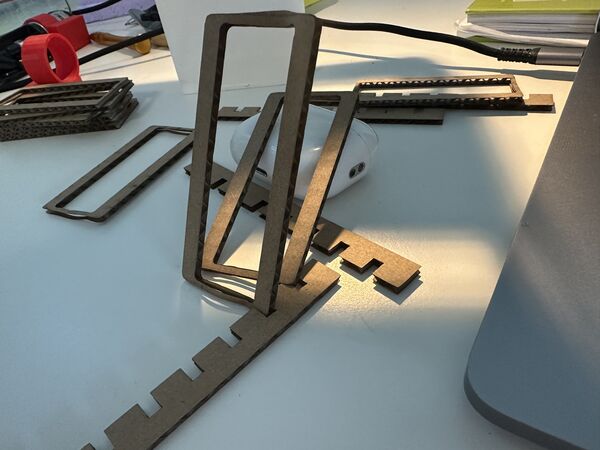
It worked but it feels a bit small
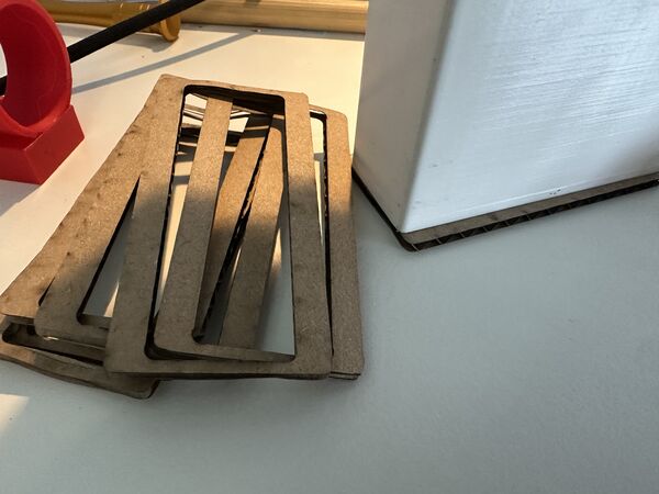
And at home I found it doesn't even fit
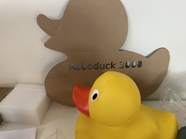
Well it's a start
Back to assembly
Time to put it all together (again).
Mounting the motors
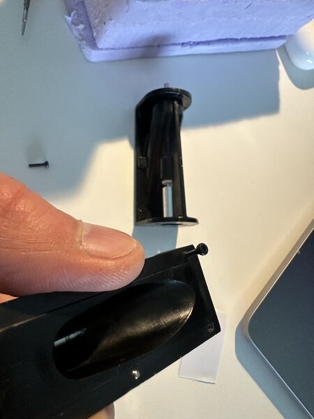
Switched to M2 bolts to fixate the motors because the imbus key is easier to use than a small screw driver. It all took some while because it's hard plastic and I had greasy hands from the experiments
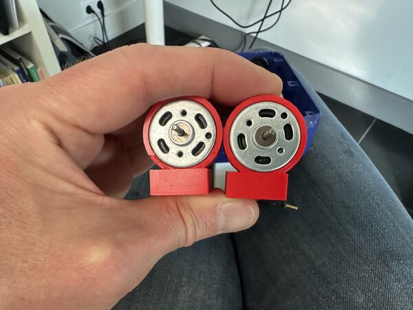
Ah ... surprise .. the motor mount are different .. I made an error when adjusting the design the last time
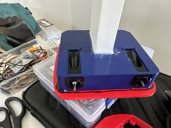
But they are now tighten ... need to apply some silicon kit now to make it waterproof
Then another problem arose ... I couldn't close the lid anymore .. because of the rings of the motor holders. So I had to make a new lid with a bigger area with a depth of 2mm this time.
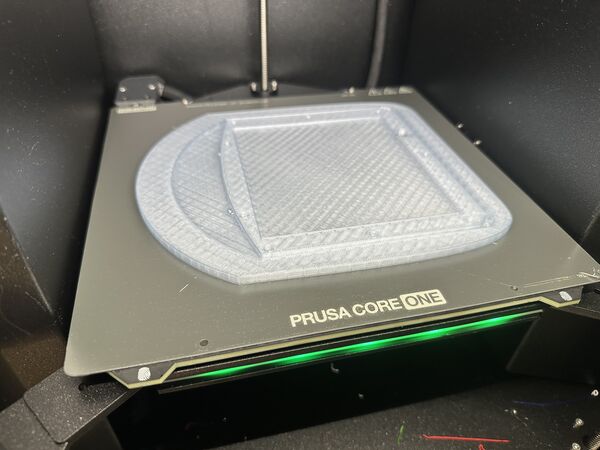
For flexibility reasons and to try something else I used PETG Transparent Blue filament
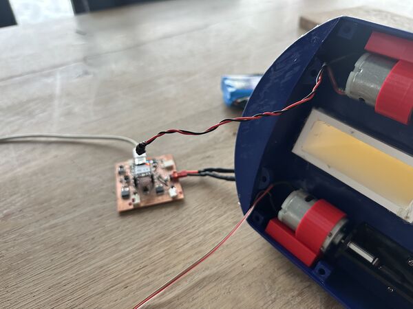
Trying out the motors I found that one of the two doesn't run smoothly.
Meaning that it gets more resistance than the other. This means that one motor starts turning at a value of 80 (from 255) and the other one at 170. That's not ok to go forward with. I have to fix this first.
First I did some tweaking with the impellor and using some extra grease. That helped a bit but didn't solve it.
Then I found out that the motor's axis was not in perfect alignment with the waterjet's axis
So my approach is to really level the axis of the motor. For that I need a new part ..
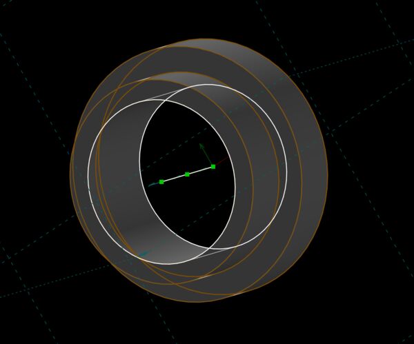
Solvespace design
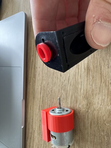
came out fine
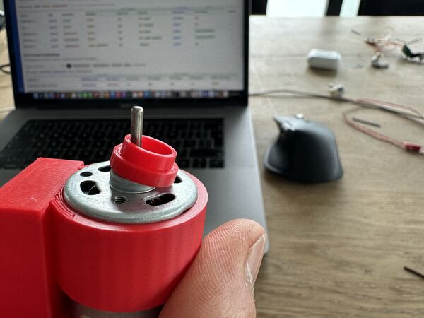
but it was too small for the motor
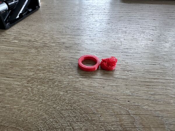
second version was even worse
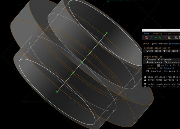
third design
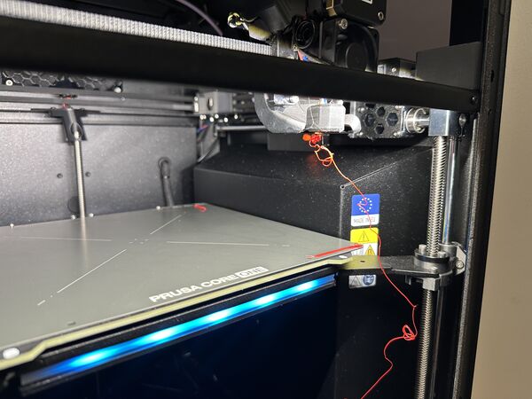
third version had to be done again
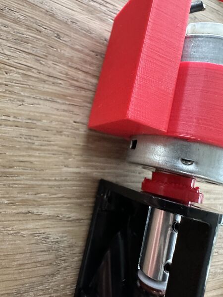
but finally it was good
Mounting the nozzles
Then it was time for the nozzles at the back.
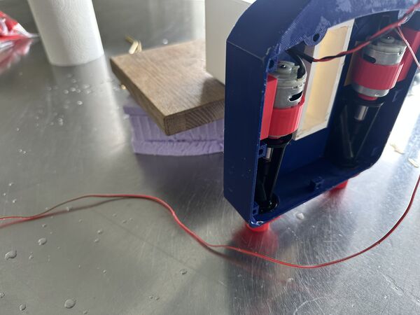
Again used silicone and basically glued it to the back
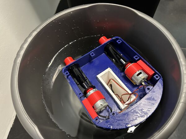
After two hours test in a bucket of water
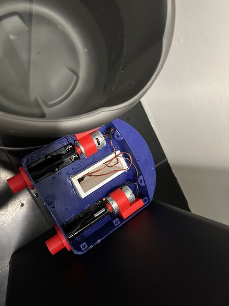
Which did not end well after 1 hour or so; the water creeped in very slowly and it tipped over; motors in the water as well
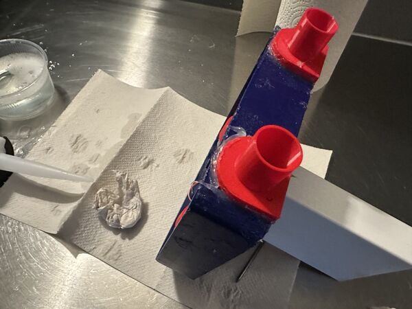
Put on extra silicone to test it again
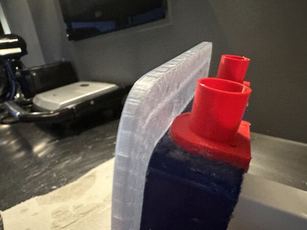
But then got a scare because the lid doesn't fit anymore; the nozzles are in the way
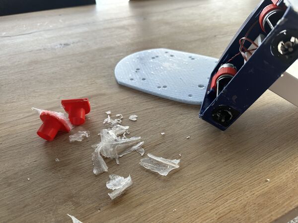
Next morning removed the silicone
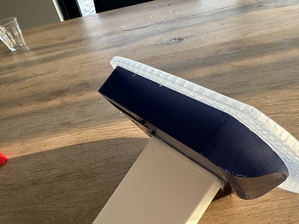
It is just 1mm or so but the lid needs to be closed as much as possible
So this means that I need to create slightly different nozzles and reapply the silicone again.
Week 20
Programming
I ended up yesterday with a adjusted UI and code for the ESP32S3 (brain) and the RP2040 (navigation unit). But because my hull disappeared under water I had to look into that first.
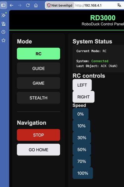
Added speed choices besided the left and right options
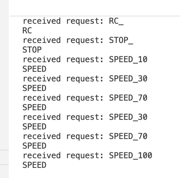
And these are received by the navigation unit as well
I worked a lot on this and in the end I got it working that an user could use the option RC to pass on commands like navigate left and right.
Assembly
In parallel I made the hull waterproof again and added nozzles upside down
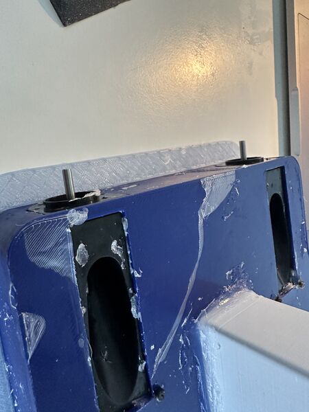
while removing the nozzles some sealing came off
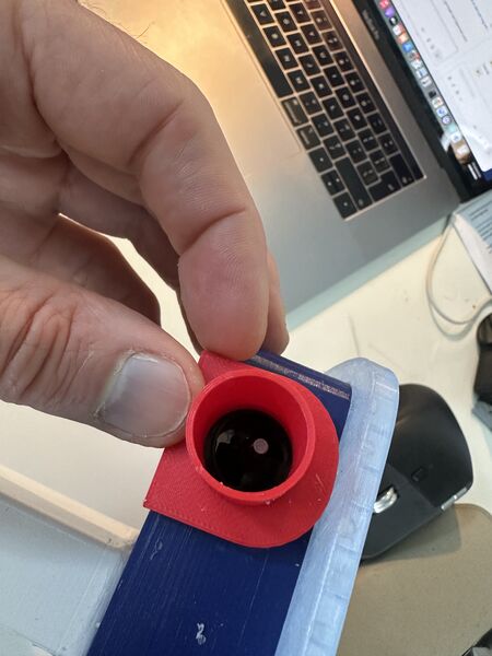
the intended way would have lifted the lid
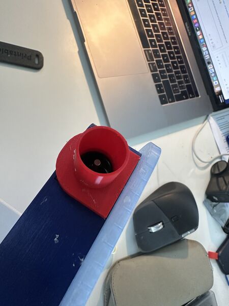
Not intended but upside down just works
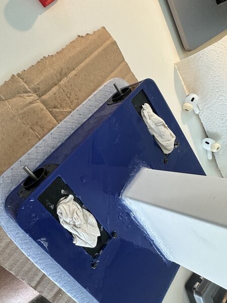
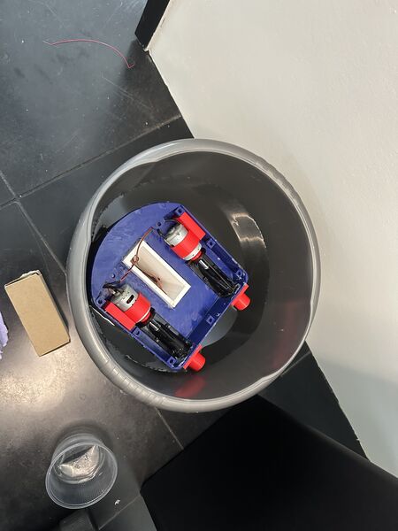
But after a small water test I was confident that it would now be ok to continue this way. I then added some of the magnets using heat from the solder iron and laid out all the components.
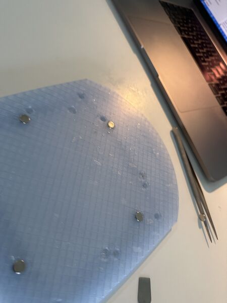
I hooked everything up and then nothing. Huh? Ah yes I still commented out the code to actually write the analogue values to the PWM ... And then? Still nothing. Ok now I don't understand.
Back to programming
I hooked both the ESP32S3 and the RP2040 again up to my machine and see that they communicate using the same code that was installed previously. Maybe the motors are broken because they took some water yesterday. So I did a quick motor test from yesterday but luckily they work. So what's the problem then?
I added some Serial.println() and they stalled somewhere around updating to pin out 3 ... well if that is the case then no wonder that the motors are not doing anything .. 3 is much too little.
Maybe it's because the handling of the event takes too long. So I2C pokes the RP2040 again and restarts? I have to lookup some code and fine tune this. I don't know yet
Back to the stand / display
Tomorrow I want to cut a newer version of the carton stand. So I updated the design
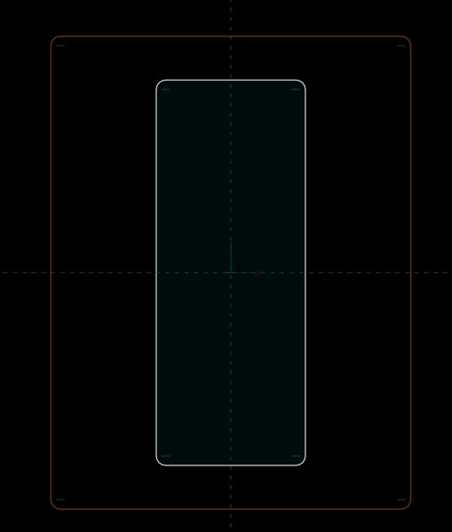
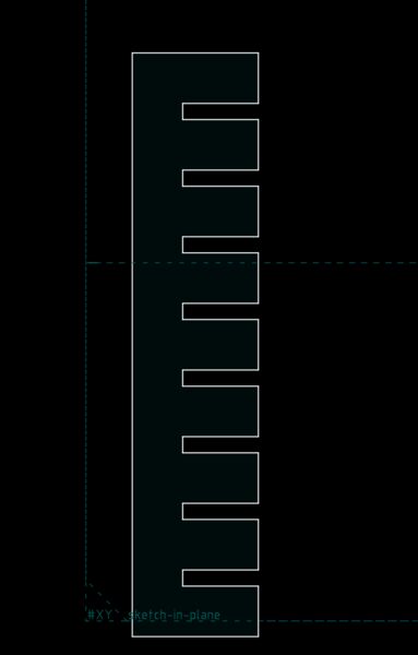
I looked up my settings for engraving during week 03 and found this note from myself
included her engraved name (200 mm/s, 15% max / 12% min power for clean filling).
Yes that's what I need to engrave the name RoboDuck 3000 onto the side.
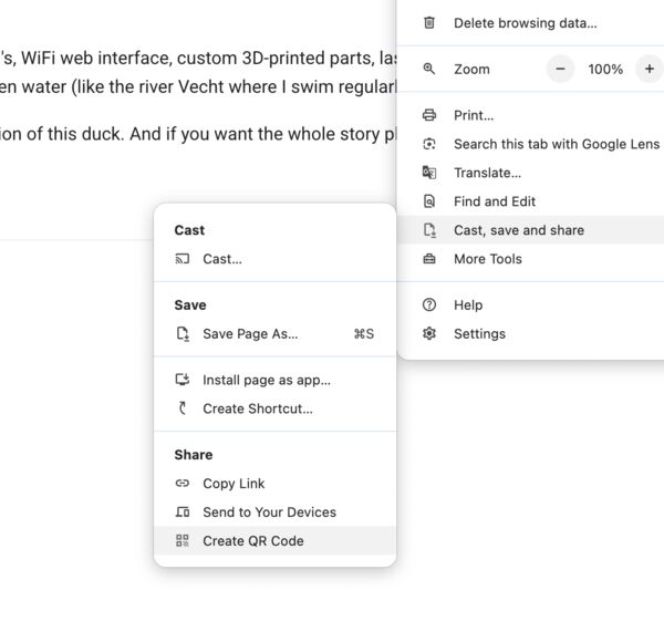
The extra that I want is also include a QR-code (engraved) that points to my final project. According to this article, Chrome actually has a built-in feature for this.
So I used my link and it created this

I tried it with my phone and it works
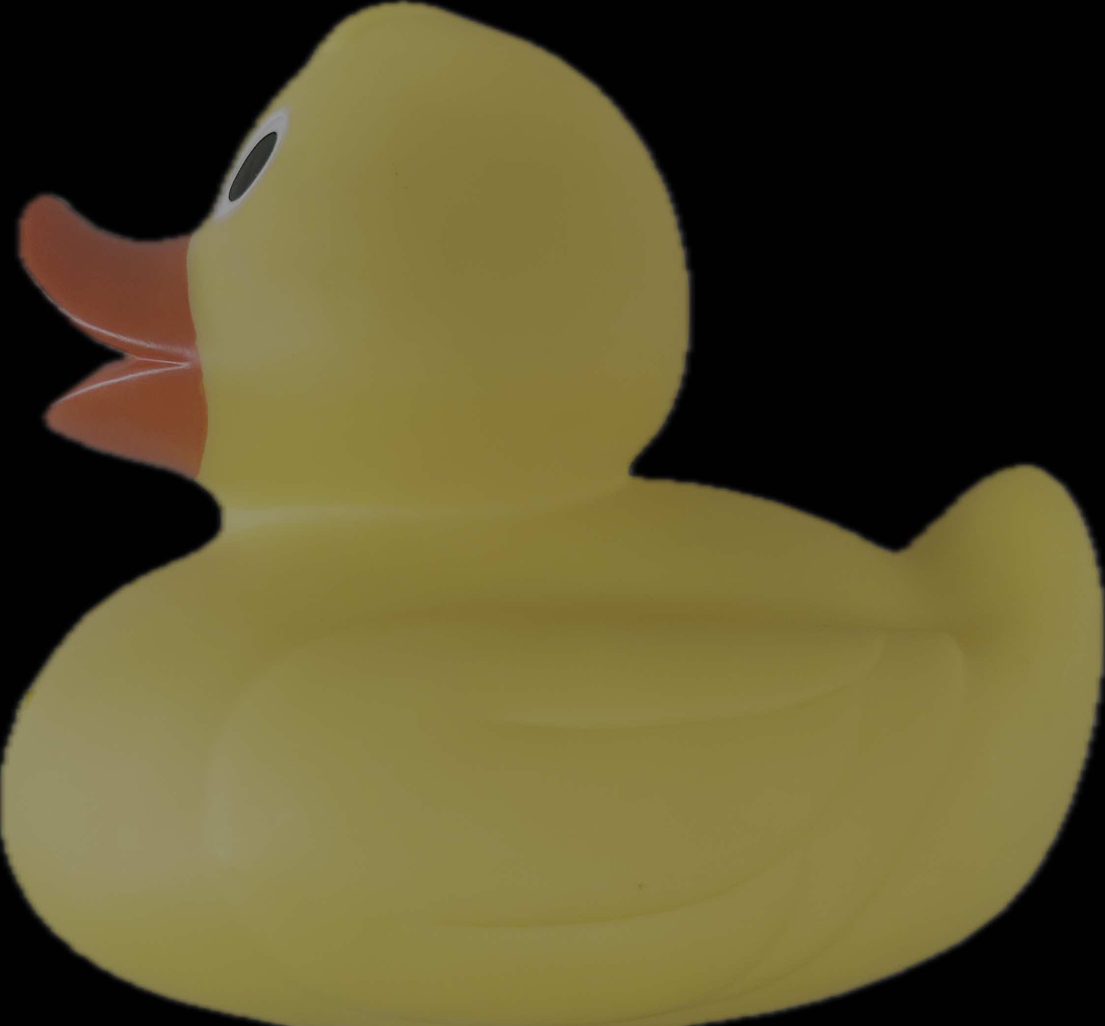
Back to the image of the duck of which I just want the contour.
I looked at this video that could help me out. First I took the SVG I had (with all the vectors inside) and opened it in Inkscape. So my idea is to selected the unwanted vectors and throw them out. But my computer is just too slow for Inkscape I think; or in combination with a file of 12Mb. It takes me ages before I see anything.
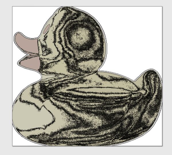
Like the last time I'll therefore do the editing in Lightburn tomorrow and just deactivated the unwanted path's; no time now to dive deep into this.
Next day I went to the Waag to try another set of cuts.
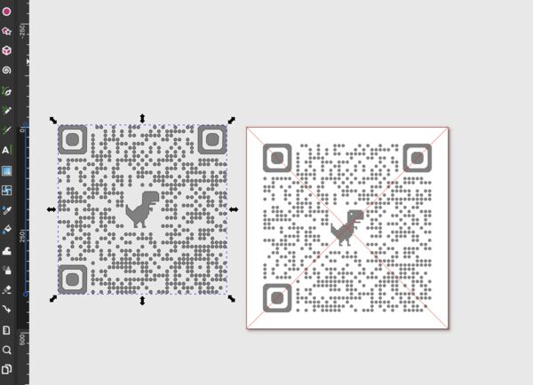
This time I managed to use InkScape to make a SVG out of the QR-code PNG using https://askubuntu.com/questions/301540/export-image-as-svg-in-gimp.
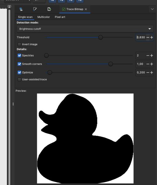
Why not try the duck again like this; yes works
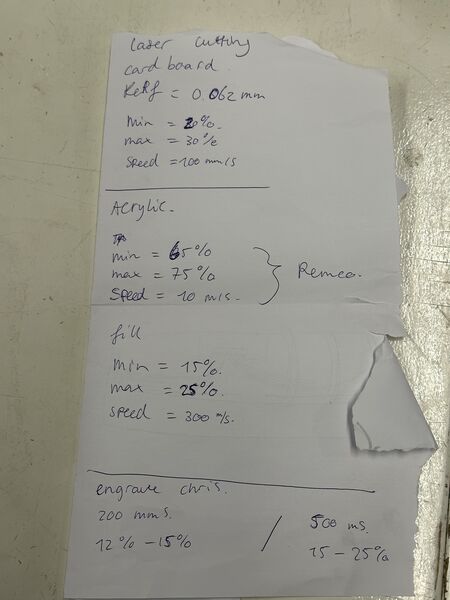
As the others also used the laser cutter that week Heleen wrote down all the settings including for Acryl
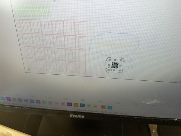
QR-code; lots of little dots
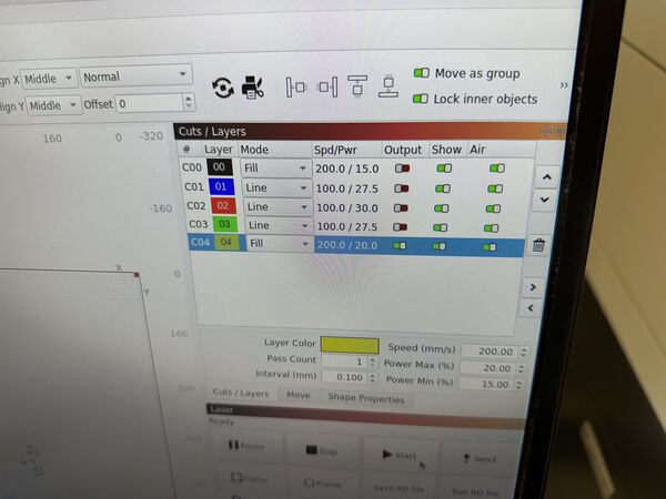
Used a fill and ranged the speed from 200 to 300mm/s with power between 12% and 25%. Anyway too little power below 20% the laser won't work. So increased power and then also increased power. I ended up with 300mm/s at 25% max. But in total I tried 6 times so actually I should do this one more time and use one setting
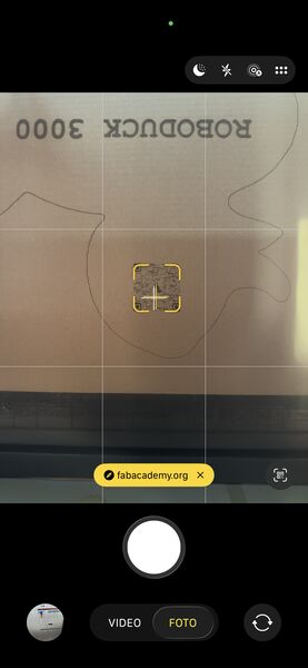
But it works
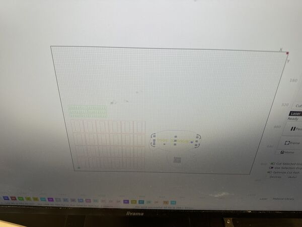
With the text I started as Line cut instead of Fill ... oops ..
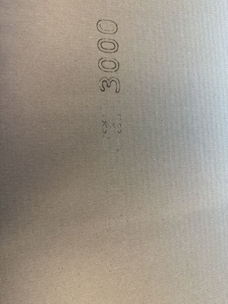
So I was glad I had set the power very low and could try it again
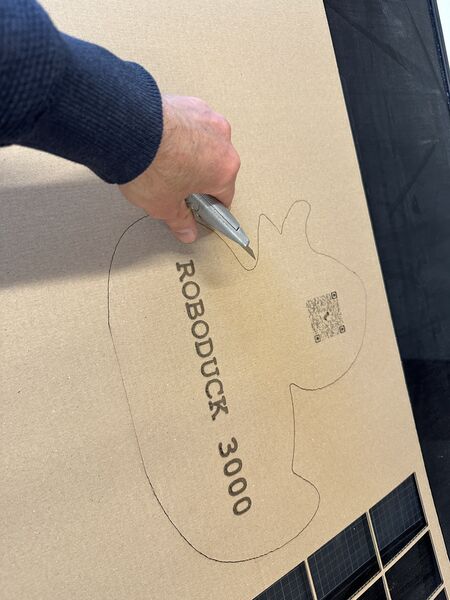
But the second time I used Fill at 250mm/s 25% max power with lowest 20% power. This worked really well
Back the sealing
I'm printing a very thin piece of lid (1mm groove) that I want to fill with silicone (and some kind of release agent). Then I want to make a contour and see if that actually is small enough to fit inside the lid to make a seal without vaseline.
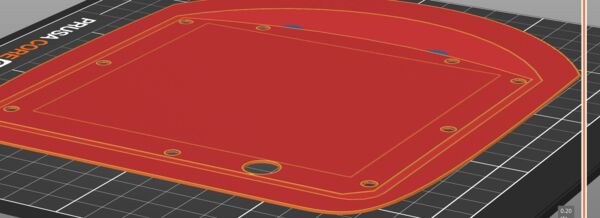
Using the same lid and use PrusaSlicer to cut it. But it still takes 1h38m (I guess because of the area anf the amount of detail).
I had to stop this job as it made a lot of noise. This time not an extruder problem but bad edges. So the area was very rough; like the printer had to throw with paint.
So redisigned a special lid for this with a base plate and 1mm thick; took me some time.
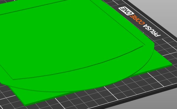
Made a new desing in Solvespace with a 1mm plate under it
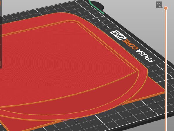
That should work
And it did.
Casting
The following morning I used it with a bit of vasline as release agent to make a seal of silicone.
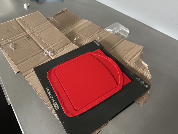
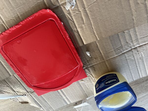
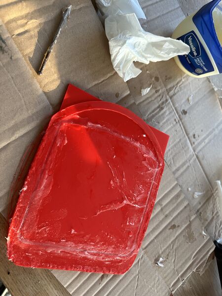
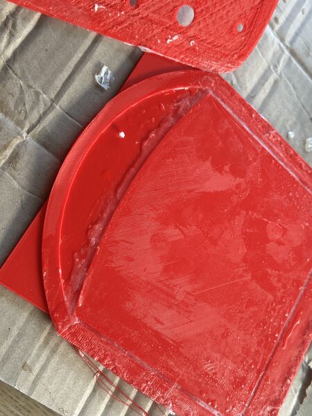
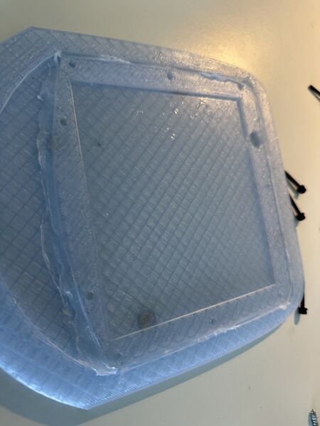
Added it to my lid
Back to one-pager
I spent time on choosing images and video's; still remaining are the ones from my action camera
Back to programming
Once my duck is on the water I don't want to open and close it all the time to update code or whatever. So I even before going into the water I reviewed/ checked / added code to really test the UI, the I2C structures, the stability and the tank steering etc.. And that actually was fun but also took me some time.
My whole idea, despite the I2C, UI etc.. is that tank steering means that going to the left reduces the power on that motor and vice versa. As I found that both motors' starting point differ from eachother and I want to gradually increase/ decrease PWM this was challenging. Also because full throttle (direction 0) doesn't mean a value of 255 on the pins; because the user can also adjust the amount of speed.
Soon I had some kind of algorithm but found that I got timing issues. This was because, when executing a PWM loop, I did this inside a I2C event. How did I found out? Well first I saw that the Rp2040 would not respond anymore after 3 steps and then Grok told me I asked Grok to check my code and gave me a couple of tips.
First of all use a kind of semaphore (boolean) to flag that I2C deliverd a new command and just store the message in that moment. Then in the loop check this flag and execute the command. While in the loop make sure that I'm not interrupted using nointerrupts. In the code I've put links to documentation that gives more detail about this
Other strange behavior I got was with Wire.requestFrom() (send by the ESP32S3). There I would ask for 20 bytes and even when the RP2040 would send only 4, 5 or 6 it would always fill it up to 20 bytes. So YES would be seen as YESYESYESYESYESYESYE (20 bytes). I did not programm this and according to the documentation this should not happen. Asking for 20 bytes does not mean I have to get 20 bytes; less is also good. So Grok suggested to request always 4 bytes and let the RP2040 send back either ACK_, RDY_ (instead of READY_). That eventually worked as well.
No time yet for GPS though ... but the UI worked solidly.
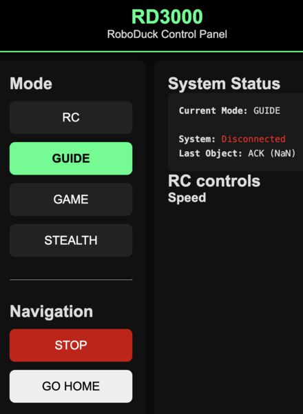
Back to system integration
Of course I now wanted to see that the motors would turn when I asked for that; time to put it to the test.
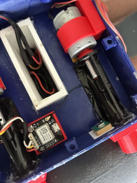
Started with the GPS sensor; nicely tucked away in the corner
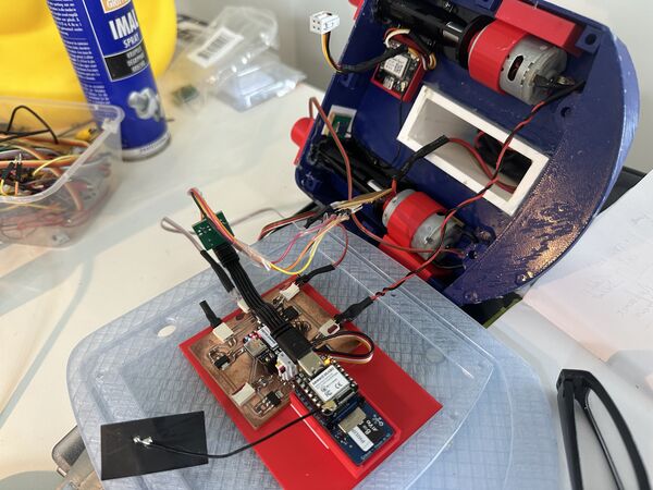
Ended up with this; but nothing. Somehow when both are connected via the computer and the PCB they communicate but using the 12V power supply no I2C communication anymore?
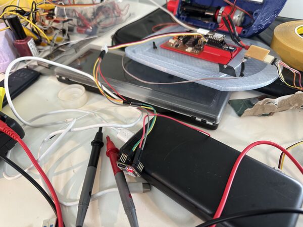
So I debugged it using hard wires from the RP2040 to the ESP32S3 and that still worked (RP2040 had power from the computer) = command came in from the ESP32S3
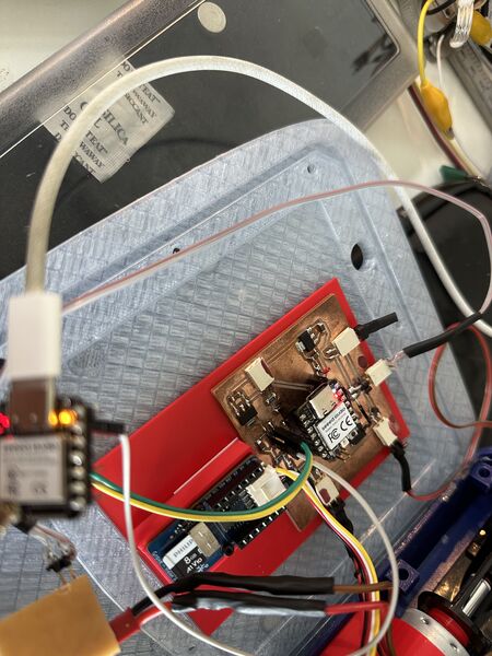
Turned around, the RP2040 on power supply and the ESP32S3 with power from the computer, that worked also BUT still with hard wiring.
Then I noticed somethingg strange, that when the ESP32 is connected first and then RP2040 is turned on the RP2040 actually won't turn on? So something is going on here which I don't understand yet.
And, when the GROVE is NOT part of the chain it all works? Also don't know what happens here. Because the Grove gets it's own power from the PCB (3V3) and closes the I2C? Is this an address thing?
Anyway I took a PCB I already made and used this to connect the RP2040 with the ESP32S; so the Grove is now out of the equation (for now).
Let's turn it on! Hmmm nothing ... Why won't the motors turn on? Then I found the most basic bug. In my motor test software (which run again flawlessly) I used the right pin numbers but forgot to set them in my new navigation code as well.
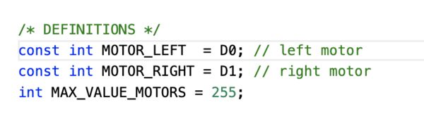
Correct
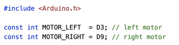
NOT correct
After this ... lift off!!
Back to wiring and making things nicer
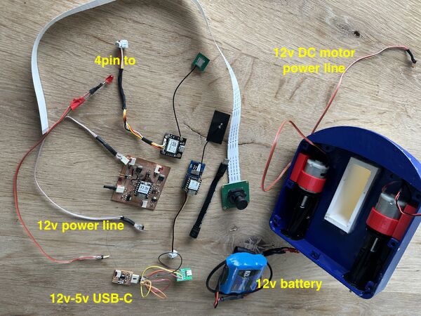
So this has to be in a little box; you see the wires I made
I found that I needed a bit more flexiblity on some of the wire because to fit them all in I need to bend them. Heleen pointed me to a toolset Henk had given her to not solder wires but basically squeeze them into a female header or male pin.
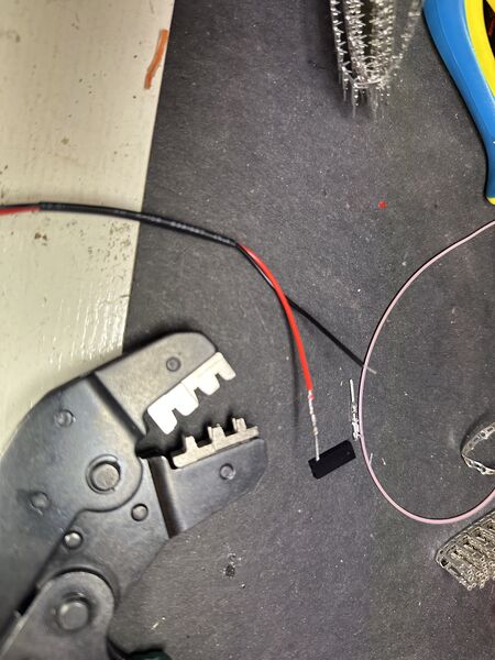
Just use this tool
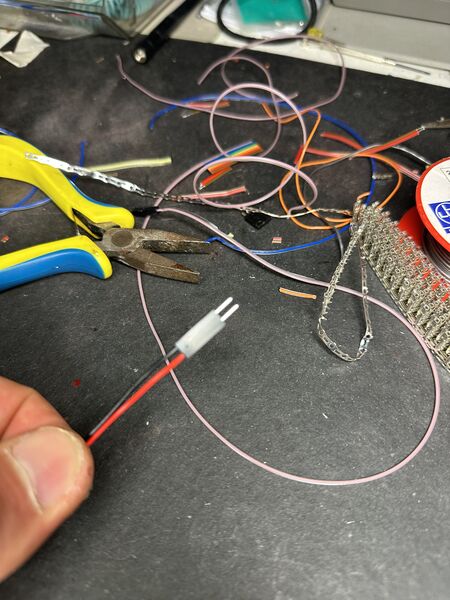
And voila
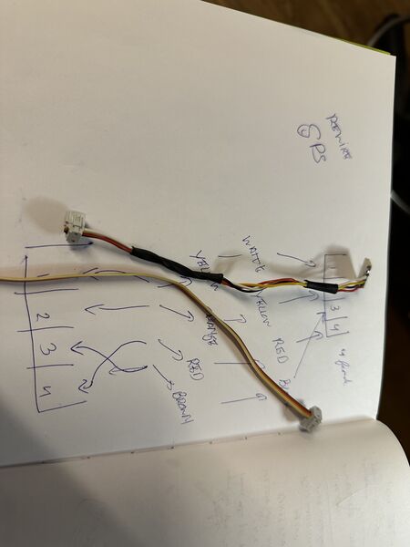
Used it to replace the existing GPS cable
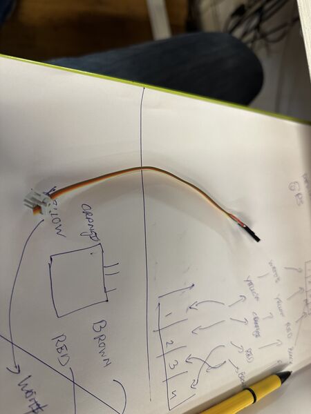
And to replace the USB-C to 12V cable
I really like this tool . It looks so much nicer
Back to 12-5v casing
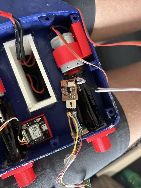
This very usefull converter was never meant to be there .. but putting it all together today ... it's fragile and I want to put something around it.
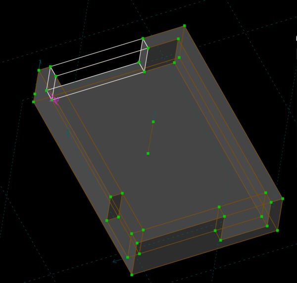
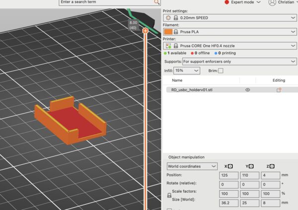
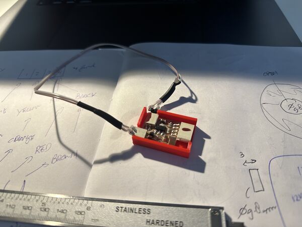
Then used that part as the base to design a small intermediate plate and the box for the USB-C board. After printing used small double sided tape that I cut to put it together
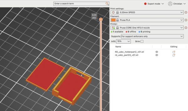
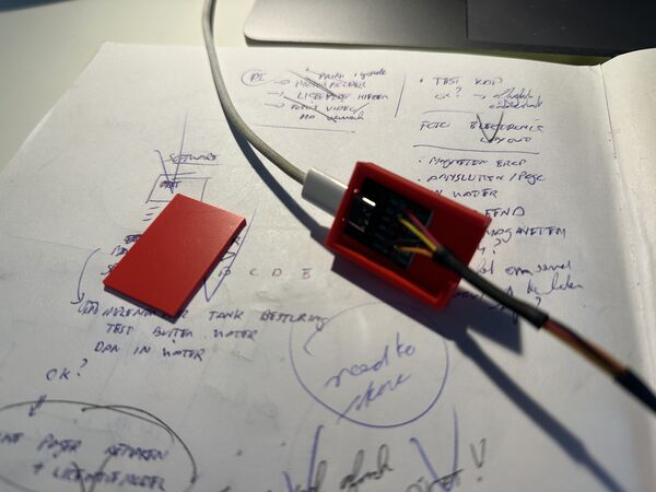
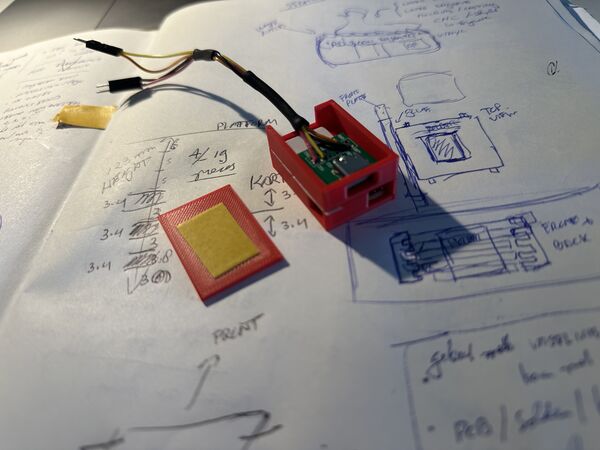
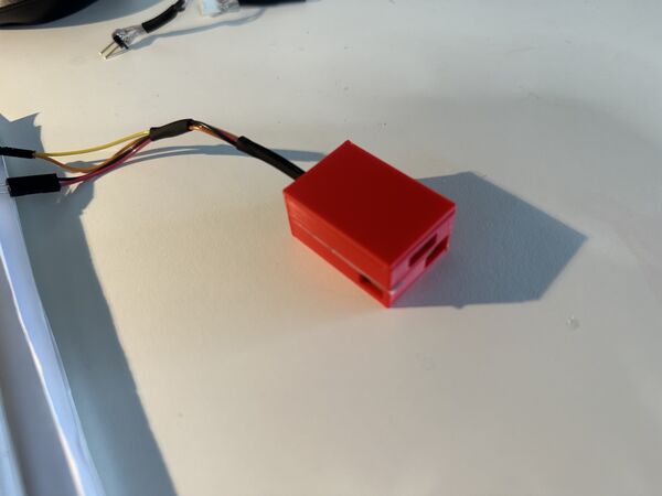
Balancing the duck
It's time to make sure the duck sits on top. For this I need to know where that is.
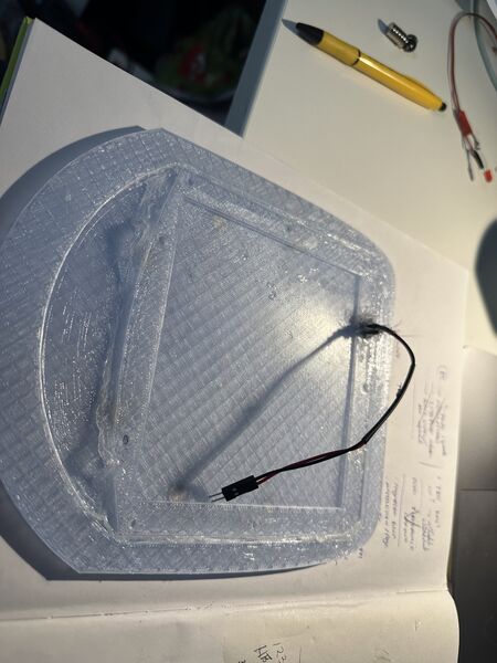
Added the pogo-pin
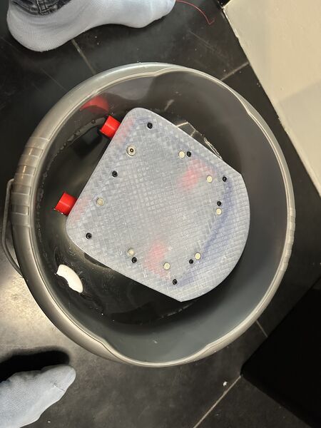
Used a bucket to see it float with the lid for the first time
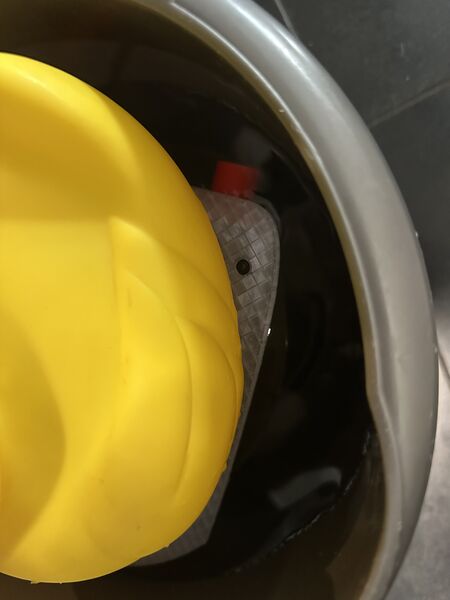
Let the duck sit on it and find the right spot. Question though is how to mark those on the bottom of the duck?
What worked good is that the smaller hull (intentional design) is now already a bit underwater. So I don't need oranges anymore for weight.
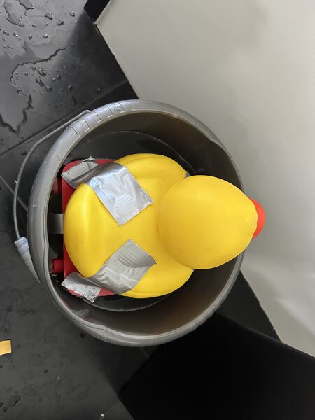
Used duck tape with a small piece of lid (1mm thin) that was loosely on top of the real lid. I would take it out of the water and the use the small lid to drill holes for the magnets.
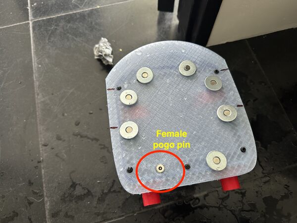
Idea is that the lid has a magnet and that the duck has a magnet with a spacer. That way the duck can move a little (because of the spacer) but still stay in position
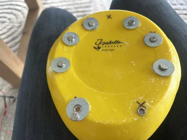
I ended up with this in the end. Sequence was a) insert in the duck to make sure the magnets doesn't fall into the duck b) space around it so that the duck can move around a little and c) magnets itself with super glue
System integration for go live
Well the software is ok for now and now the duck can stay on the lid I did some final checks and modifications and put it all together again
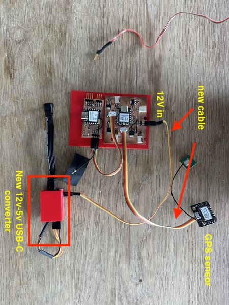
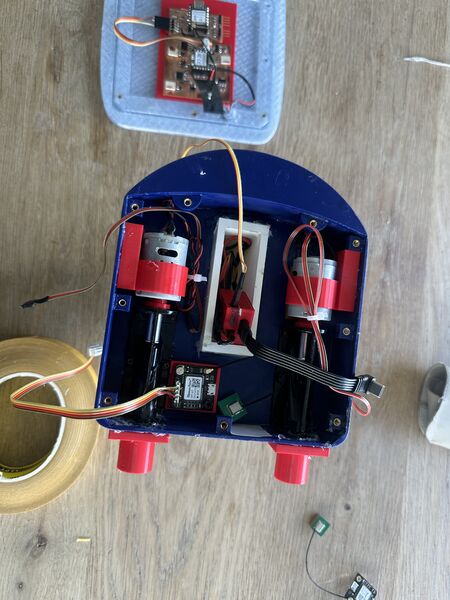
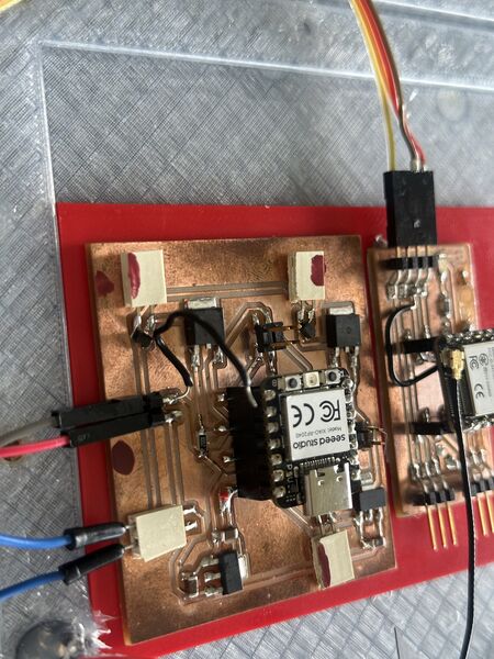
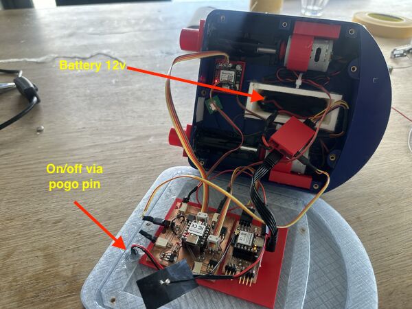
GO TIME!
Everything set let's go
To make sure I would get no water in I used vaseline again; last test showed that this very reliable.
Soon after I put the duck in the water the right motor turned off which was curious; then almost no power on the left motor which also surprised me. So I took it out
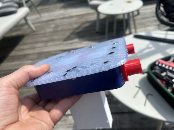
looks normal on the outside afterwards no visible leaks
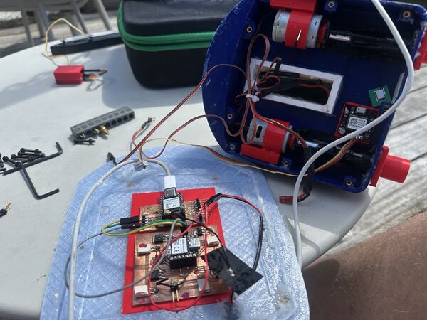
but completely soaked at the inside
Analysis
So that was very disappointing. I was able to have some control but soon the right motor was not doing anything anymore and then the left could only make it spin around. The next day I noticed a couple of things after I let it dry:
- bolts were already rusty (cheap quality apperantly)
- some of the nuts were a bit elevated (so I think I pulled a bit tooo hard and/or the attachment was to weak; none of them was loose though)
- battery was now only producing 5v and something. So this was basically the main reason everything broke down I guess
- when connected to my computer the RP2040 and ESP32S3 were still functioning; have to test them further though
PREPARING FOR 2nd GO
I fixed up the inside, like cleaned it, pushed back the inserts with a solder iron, gave the motor axis some extra grease, glued the GPS antenna to the side and glued a bit of the motor wiring to make some space.
Then tried to power everything on again which seemed fine; except for that smell. That was a bit worrying. The Wifi still worked and so did the startup page. But when giving it commands to power the motor nothing happened. I knew that the motors were still working because I tried that yesterday. So either the MOSFET's were gone or something else?
I therefore decided to first run the motor test program on my RP2040 to see what would happen. This even works with no 12v attached. I uploaded the program , which worked fine, but then no output on the serial monitor? After a couple of tries I just hooked up the ESP32S3 and that one worked fine. And a ESP32C6 and that one worked as well. Ok, I guess the RP2040 is gone then. To be sure I hooked up the motors but nothing happened. Well the RP2040 is probably broken (or just the hardware serial) and/or the MOSFET.
I therefore decided to take one of the Xiao ESP32C and put the test motors program on that one. But it appears that some of the instructions were not understood like analogueWriteFreq and analogueWriteResolution. Therefore had to dig into the XIAO ESP32C6 PWM stuff. Seeedstudio offered a start with more info about PWM. Saying that there are 6 PWM channels mainly meant for LED's but can be used for other purposes as well. They referred to the producer of this chip for more info.
It appears there are special functions for LED's but that also the functions I use are known; but they have different parameters. Well that's easy. So I changed these instructions to point out the specific pins like
  analogWriteResolution(MOTOR_LEFT,resolution); // sets the resolution
  analogWriteResolution(MOTOR_RIGHT,resolution); // sets the resolution

  analogWriteFrequency(MOTOR_LEFT, frequency);
  analogWriteFrequency(MOTOR_RIGHT, frequency);
But nothing audible happened :sad:
To test at least something I took a small test program from the website from ESP32 to show a blinking led using the more sophisticated instruction set.
/*
 LEDC Software Fade

 This example shows how to software fade LED
 using the ledcWrite function.

 Code adapted from original Arduino Fade example:
 https://www.arduino.cc/en/Tutorial/Fade

 This example code is in the public domain.
 */

#include <Arduino.h>

// use 12 bit precision for LEDC timer
#define LEDC_TIMER_12_BIT 12

// use 5000 Hz as a LEDC base frequency
#define LEDC_BASE_FREQ 5000

// fade LED PIN (replace with LED_BUILTIN constant for built-in LED)
#define LED_PIN 0

int brightness = 0;  // how bright the LED is
int fadeAmount = 5;  // how many points to fade the LED by

// Arduino like analogWrite
// value has to be between 0 and valueMax
void ledcAnalogWrite(uint8_t pin, uint32_t value, uint32_t valueMax = 255) {
  // calculate duty, 4095 from 2 ^ 12 - 1
  uint32_t duty = (4095 / valueMax) * min(value, valueMax);

  // write duty to LEDC
  ledcWrite(pin, duty);
}

void setup() {
  // Setup timer and attach timer to a led pin
  ledcAttach(LED_PIN, LEDC_BASE_FREQ, LEDC_TIMER_12_BIT);
}

void loop() {
  // set the brightness on LEDC channel 0
  ledcAnalogWrite(LED_PIN, brightness);

  // change the brightness for next time through the loop:
  brightness = brightness + fadeAmount;

  // reverse the direction of the fading at the ends of the fade:
  if (brightness <= 0 || brightness >= 255) {
    fadeAmount = -fadeAmount;
  }
  // wait for 30 milliseconds to see the dimming effect
  delay(30);
}
Using the pin 0 on my board (where I wanted to attach the Duck's head light) that actually worked fine
Back to the original program I had for the RP2040 I rewrote it to use this instruction set ... But I couldn't get anything out of it. I caved (sorry about that) and asked chatgpt why it wasn't working. I could not give me real answers; well not anything that I did not already know (commong gnd, right pin, MOSFET's should be ok; etc). But it sugggested to use a full 3v3 on the pins to just see if I would get anything using this small programm
#include <Arduino.h>

const int MOTOR_LEFT = 21; // D3 AND for the RIGHT MOTOR I found that D9 = 20

void setup() {
  pinMode(MOTOR_LEFT, OUTPUT);
}

void loop() {
  digitalWrite(MOTOR_LEFT, HIGH); // MOSFET on
  delay(2000);

  digitalWrite(MOTOR_LEFT, LOW);  // MOSFET off
  delay(2000);
}
Running this gave a small tick from both motors. So yes there's is something happening and pin 20 and 21 are the right ones to use. Then I just put 3v3 on one of the motors from the ESP32C6' pin and the motor worked??? But why is digitalWrite() not working then? Ah of course according to SeeedStudio the 3v3 output is regulated by the ESP32C6 and can deliver 700mA; yes that is more than enough. However each pin can deliver much less; usually around 50mA max so that explains it.
Whatever I do now ... I need more current and therefore the MOSFET's ... so let's test that code again but now with the MOSFET's.
But it doesn't work. And when I measure one of the voltage regulators that supposed to convert 12v to 3v3 .. it measure around 11v5. So my guess that some stuff is broken and rebuilding the PCB etc would be the best option. Well then of course I would include the new USB-C schema as well. But for now, today, this is it with the board.
My conclusion sofar:
- The Xiao RP2040 is broken. It accepts new code somehow but it's serial communication is gone
- It's doable to swap the RP2040 for the Xiao ESP32C6 (I'm sure I will solve the coding) BUT without a working MOSFET I'm never going to really get the power out of it and I think the MOSFET's are both gone anyway
- While checking the PCB for further issues I found that one of the voltage regulators (12v - 3v3) now gives 11v ??
- The good news is that the ESP32S3 actually still works; anyway the Wifi and the serial communication
But I've to admit that my second go is not going to happen. Because just doing the same PCB again is a waste of F1-material. I would then like to include the additional 12v-5v USB-C converter and get rid of the 3v3 anayway. I would also change the layout so that wires run more smoothly.
Final thoughts
I was reviewing all the photo's / video's and said to myself "we did a lot". And with that I mean "we did so much in such a short amount of time". Amazing, even for me. So to end in good spirits I shortly reflect on my journey.
What went well
- Although difficult from time to time, I managed to keep my sanity and stayed true to the idea of spiral development throughout. I killed my darlings on numerous occasions and that kept me hitting deadlines.
- Reusing an existing rubber duck was a good decision. It saved time and gave my idea something to work with; also a purpose to envision this duck on the water
- The web interface/ wifi works surprisingly well, even when I did a test whereby I submerged the ESP32S3 a bit under water.
- The use of magnets to keep the duck in place and make it easy to take it off again
- The pogo pin is crap quality but the idea is good
- Decision to go for 2 motors was worrying but tank steering appeared easier then I thought
- Also using Dichtol to waterproof the outside printed parts; that works very well
- Using as a C4-model helped me design a good architecture
- And doing all the tests ... they were time consuming but helped get more insight and make decisions
What was challenging
- Primarily water proofing ... very time consuming .. Especially the lid / hull connection. Vaseline works kind of but is messy.
- Power stability issues (brown-out and power bank shutting down) caused me several setbacks and forced me to iterate on regulators and wiring. I had fun learning but again took time
- 3D design in general was a thing that I was scared of. But somewhere in the last 5 weeks "het kwartje viel" (the pennie dropped?). I suddenly understand
it. So in the beginning 3D design was more time-consuming than anticipated — especially boolean operations and getting the hull shape right around the waterjets and battery. - Debugging the code / communication / getting the right PWM on the motors ... it all took more time than expected
- But getting near the deadline and still not have had a chance to get into the water with my duck ... that was really mentally challenging.
Overall lessons
Is there something like overall lessons after 20 weeks of hard work and feeling like being in a continous rollercoaster? But if I look back on the reason why I started this (getting to know more than just software) I think that I really learned that "it is possible to almost anything by yourself".
Besides that:
- test/ fail early is the only way
- assumptions are the mother of all f...ups
- kill your darlings
- system integration is where the mess starts
- make it nice!! (I get that now)
- I know so little
Want to make this yourself? See Summary and do-it-yourself