Week 16 – [System Integration]
Dates worked: [May 6 - May 13, 2026]
Time invested: ≈ 69 hours (spread over 8 days)
Extra info
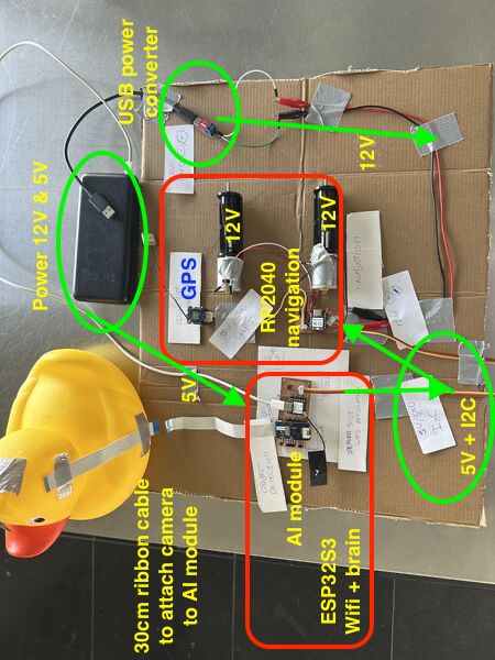
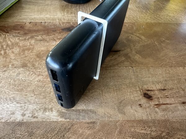
Based on feedback from my global evaluator I want to add some extra info regarding power converter that is part of the system design. Please see this small board. Using it's dip switches one can use a powerbank that has USB-C output and convert it into either 5v, 9v or 12v.
My inital idea was to use the powerbank as weight/ keel and use the normal USB-A connection to supply 5v to the microcontrollers and provide 12v to the motors using this board. However I later found, in week 18, that the power bank turned off during low-current tests. Also found that the power bank can either deliver 5v or 12v; not both at the same time. In week 18 I therefore switched to use a separate 12V battery with step-down regulators for stable 5V/3.3V supply. More in depth description final project blog - week 18.
Quick summary of my week
This week I finalised/updated the C4 system diagram (context + containers), redesigned the hull v3 in SolveSpace with proper water-jet inlets and battery keel, printed and tested multiple iterations of the battery holder and rear hull section, and clarified the communication protocol between the ESP32-S3 (brain/WiFi) and the RP2040 navigation board.
I also ran real-world tests with the water-jet pumps and started thinking about packaging, strain relief, and “does this look like a finished product yet?”.
I think this falls under sprial development, and I really liked to make the mockups but had frustrating CAD sessions. I do think the overall design is more coherent now.
Requirements & objectives
I believe I have fully met the learning outcome: Define and apply system integration to my final project.
- [x] Made a plan for system integration (updated C4 diagrams + subsystem descriptions).
- [x] Documented the plan with CAD, sketches, cardboard mock-ups and photos.
- [x] Implemented most of the methods of packaging (connectors, cable routing, Dichtol waterproofing)
- [x] Documented the system integration (not only this week but also seperate pages in my final project section)
There was no group assignment this week.
Learning outcomes demonstrated
Looking at the learning outcomes for this week:
- I defined the overall architecture using the C4 model (Context + Containers).
- Translated high-level subsystems (Navigation, Object Detection, Brain, UX) into electronic components with connections and communication protocols.
- Iterated physical integration of the water jets and the power bank through 3D-printed prototypes; and a bit of water test
- Paid attention to “finished product” aspects: rounded edges, strain relief thinking, neat cable routing, and a hull that no longer looks like “a box with a duck on top.”
- Documented trade-offs (e.g., why I moved from one PCB to direct Grove connection, why two water-jets instead of one).
All evidence can be found in this week and my final project documentation to which I've linked
My week – how it actually unfolded
Day 1 - [Wednesday - Regional / Global session]
In the morning I basically updated my documentation.
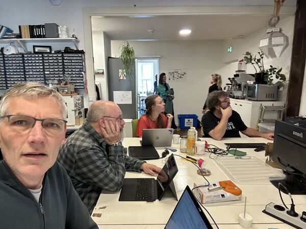
At the FabLab Henk talked briefly with us about our upcoming week and only 4 weeks to go before our final projects have to be finished. After that we had regional reviews.
Global review
Neil had help from Fran - student from 2013 who's taking up the reviews together with Jogin (student 2017). Like many others I've seen a couple of video's from Fran describing live at the FabAcademy. He apparantly returned as a 'viewer' student again in 2024.
Take aways:
- Take time to test your assumptions. For instance torque of motor could not be enough if you want to move a lid
Neil mentions: "Connector needs to be inside the board; otherwise solder will brake when there's force put on it"
- Spiral not serial development
- Work back from the schedule; not forward!
Global class
Neil: "System integration describes all the elements in the system and how they come together"
Main take aways: This class is mainly about possible failures
Design
- presentation from Jan about how to make almost anything useable
- BOM: plug-in for Kicad
- HOWTOONS cartoons on how to do things
Packaging
- Wiring is frequently cause for failure. Shows example were student designed the routing of the wiring
- Surface finish; for instance instead of just 3D printing
Testing
- Quality assurance is preventing defects (creating more space around the traces)
- Quality control is defect detection
- Shake it; drop it
- Burn-in is run it for a day!
So a lot of ways but I will remember Neil's remark "A good way to test something is to take it apart and put it together again."
Failure modes
Stress curve: for moving parts you want to know where the elastic limit is
- Don't use sharp corners but rounded ones to reduce stress
- You always want some sort of strain relief on a cable so there's no stress on the wiring
- Make sure you can connect cable only 1 way
Components
- Motors go out if you go beyond the load, temperature, current they can handle
- When a magnetic field collapses it tries to retain it; this causes the current to flow the other way. So to protect your circuit use a flyback diode
- Power the wrong way you can blow up; use a diode
Put a resistor between a component and a pin of the MC to reduce the flow of current. So we used this before to protect a LED (outgoing) but it could also be that there's a sudden spike coming towards the pin; then it will protect the MC
Power
- Voltage drops when supply can't handle the current (I saw this last week when the AI module turned and the ESP32S3 had to little power; it rebooted; brown-out; of course we also saw examples of this during our output week)
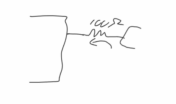
- Wiring acts as inductors!
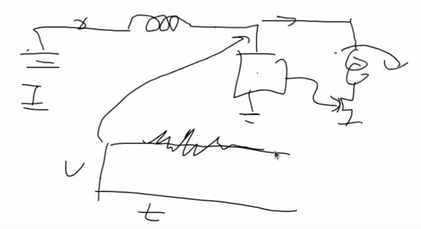
Voltage should be constant but when the motor turns on it jitters. Solution is to add a capacitor next to each important component of around 0.1 and 100mF next to eachother ... the little one will get rid of the noise .. the big one will make sure the power will remain the same
During the lecture I thought my final project; I've added those there
Day 2 - [Thursday]
Started at home to write down some idea about my final project.
Then we had a local meeting to go over our final projects with eachother.
Although I felt like everybody is getting more nervous, it was actually nice to take some time and share our thoughts.
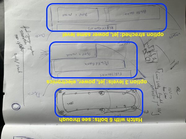
Before local session on Thursday I had a couple of ideas to place the components. My concerns are still a way to open/ close the hull to charge the battery and placement of the power bank relative to the water jet for stability of the duck.
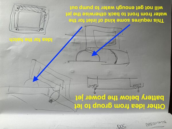
Preferably I would like to lower the battery but the water-jet needs water; so placing it below the jet would be very difficult I thought. Henk/Remco suggested to create some kind of tunnel and place the battery below that tunnel. Remco showed me what they meant.
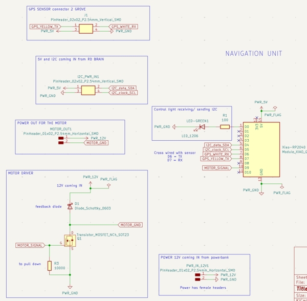
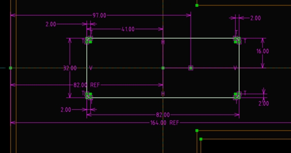
Afterwards I worked on the design of the PCB for the navigation module and, in the process, already did some work on cables.
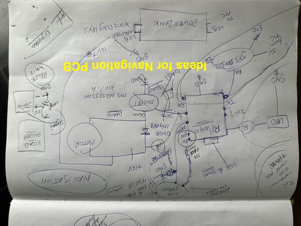
Design for navigation unit that controls micro servo, DC brushed motor and get's input from GPS sensor
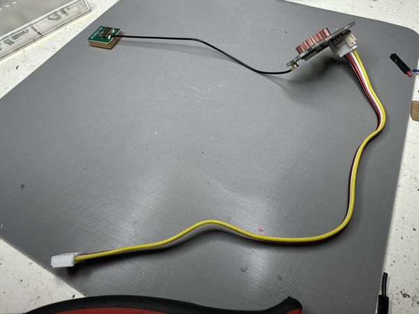
GPS sensor use a special grove cable that has different measurements than the male pin headers we used before
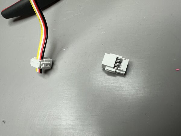
I thought of using the same type of connector we used for our group assignment. No soldering needed
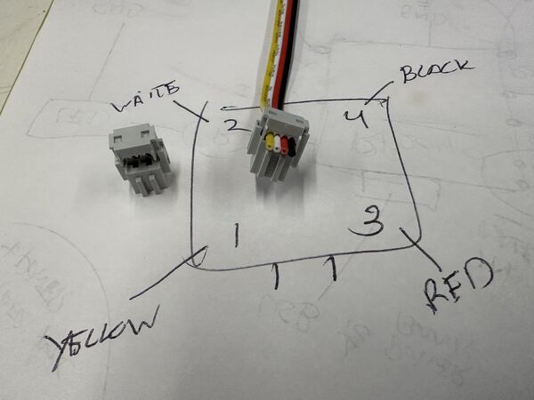
Need this in Kicad later on
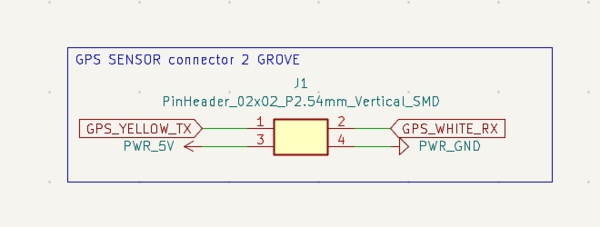
Connector in Kicad
End of day in Kicad
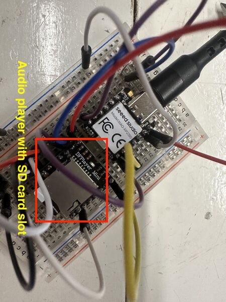
Remco worked on his sound engine. He uses a special module for this. Maybe I'm going to use it too
Note
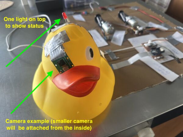
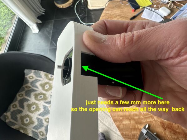
Henk suggested to place the camera inside the duck from the back of it's head. His tip: make a 45 degrees cut so you can put it back easily again.
In the evening I drew more sketches for my hull design.
Day 3 - [Friday]
Update my documentation from yesterday first.
Working backwards
Created a process flow for myself (based on experiences sofar) how I want to work towards the final presentation.
This also helped me to create a workload as issues in GitLab
Make something usable
I wrote down some tips from Neil that I transferred to my final presentation page. But in between I also took a look at the presentation of Prof. Dr. jan Borchers about how to make almost anything usable. Idea behind is that now I can still change my design if needed.
The presentation itself had no notes but I got a pretty good idea of it's intention. Based on what I read I've raised some questions for myself
User - task - context
Let's work backwards and look at my intended modes of operation:
- Wildlife/ stealth mode — it goes quiet and observes wildlife/ takes photos without disturbing the scene
- Game mode — it actively chases and tags swimmers with a cheerful quack
- Swim mode — it swims steadily in front, maintaining perfect distance to lead the road
In order to prevent RoboDuck (RD) from swimming to Tokyo it needs to know within what boundaries = geofence; can be told during startup. For now this can be hard coded.
Somebody has to tell it how to behave once it's in the water.
Context: If the user wants to be chased = game mode or swim with it, then RD will most probably be operated by the person that is going into the water as well. I'll call this person swimmer for now. This person might be still dry or not, but it means that, given the current UI, it has to be done outside the water. My concern is now if this will be ok; nobody wants to loose their phone in the water or something.
If RD is operated by someone that stays outside the water and let's others have all the fun, then the current UI will still be sufficient.
Context: If RD is meant to just act like a duck and do it's thing, then operating RD can be done with no problem at all as the user does not enter the water him/her self.
So this means I have to come up with another type of UI later on for swimmers how themselves want to operate RD before, during a game
Gestalt principles
I had to look this one up. According to this website
the 9 Gestalt principles are essential for designing user interface layouts. Proximity, similarity, enclosure, and more guide the eye, turning visual chaos into clarity.
Ok so this sounds like a rabbit hole for me right now in which I don't intend to dive. From previous experiences on projects I know this is a profession by itself.
Avoid modes
Ah yes I've modes of operation. So no avoiding there but I will make it clear to the user how to select a mode and what it means in the UI
Principles of least surprise
Also looked this one up.
POLS is a guideline that says any should operate in a manner that surprises the user as little as possible... This rule minimizes the learning curve of a product to improve user convenience.
Ok, I'll keep that in mind.
HOWTOONS
Love it. But how I create something like that I don't know. And I guess it will take me a lot of time. So no. I'll boringly just write down how to assemble the duck once people have the parts.
BOM
I already started a BOM.
Neil referred to a Interactive HTML BOM generation plugin for KiCad, EasyEDA, Eagle, Fusion360 and Allegro PCB designer which I'll put on my list of todo things.
Day 4 - [Saturday]
Started with the battery holder. Decided to let it all the way down instead of just a bit. I remembered from sailing boat design that a full-keel sailboat is good for long journeys as there are heavier and less maneuvrable. So waves hitting will not do much. As my duck needs to maneuvre I decided to go for a normal keel; meaning it's much smaller and goes more down.
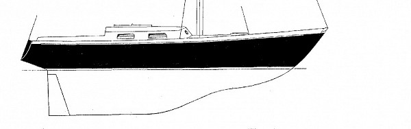
Good design for long journey where you go in one direction most of the time.
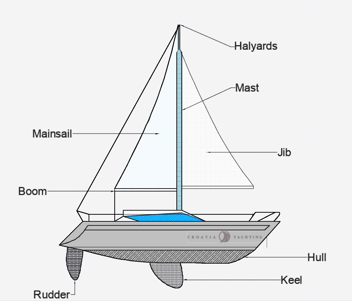
Easier to maneuvre
To summarize this whole day ... it was mostly frustrating.
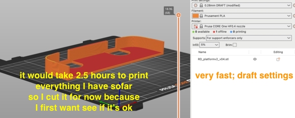
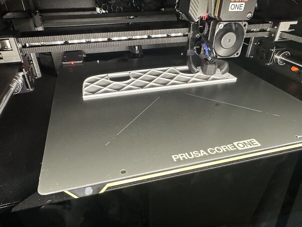
At the end of the day I managed to print part of the battery holder (to measure if it is ok) and a piece of the hull at the rear end.
The reason it's only a very little piece is because of the fact that the filament in my printer blocked; it curled in such a degree that it made a knot. So after fixing this the printer continued 5mm above the actual object. My guess is that the printer took some time before detecting the problem and that it therefore thought it was continuing at the same place. Sorry no photo's this time. I was too hasty to get my print
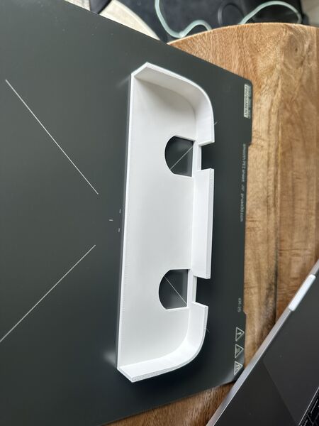
But anyway this fits very nicely
Might a bit too wide but let's wait and see. Two powerjet's and a battery in the middle should be no problem
Day 5 - [Sunday]
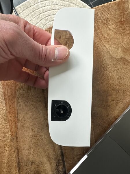
Started with a small test of the current v1 design with the motor. Now that I've attached the nossle outside to the waterjet I still want to see how the flow of the water will be.
running at 6V it worked until it didn't anymore; the motor shut off
Second try lasted longer; again only 6V
What I learned from this small test:
- alignment of the axis of the motor and the shaft should be near perfect to prevent friction
- going for 2 waterjets is still a good idea as one might just be not enough
- the inlet does not necessarily have to be just beneath the bottom; it's now working as well while there's a distance of 3mm between the water and the inlet
- Last settings (0.25 SPEED; 10% infill; PLA) might be enough already to print the hull
Then onto working backwards again.
I visualised my workflow/ process
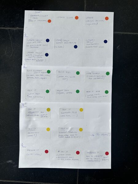
Read from top to bottom; colors represent categories of work
So regarding the colors:
- Orange: relates to what (scope) and why
- Blue: design of what I want to accomplish
- Green: build according to design
- Yellow: test what I've built according to what I want
- Red: make it presentable
Then went through each step and wrote down same and new ideas on a post-it and categorized them.
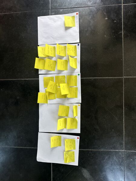
most stuff still regarding design and built
Note
I've written down these post-it's as issues so that I can track them Kanban style
During a brake I thought about the design and had some questions:
- My plan was to have the AI module
talkto aESP32C6and connect that one to theESP32S3. But why not link the Grove AI module directly to the ESP32S3? It willonlydo Wifi with some user interaction and ask questions/ send commands to thenavigationmoduel. It saves me a PCB, soldering and space inside the platform. - Thinking about global class comments about
let users see what mode it's inI think it is a good idea to put a big neo pixel in the top of the duck's head. I can probably use this to show modes of operation using different colors(?)
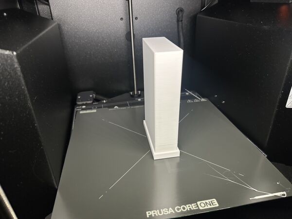
Then went on to design the battery holder and printed that. To summarize it took me a while. At one point I was already printing and just in time stopped that process because I forgot to design a bottom.. The end result was satisfying though.
Day 6 - [Monday]
I started the day with trying to model the waterjet in 3D to import it as assembly (like a part) in the design of the hull. Goals was to model the holes for the nozzles at the back. But what went fast yesteray didn't go at all today... ARGHHHH
Good intention
Well getting nowhere this way
Based on earlier checks I already knew that the height of the read end was good enough. So why not just model it straight into the hull design; do it all at once: the hull, placement of the waterjet holes, motors and the keel. But after an hour I just stopped. Somehow SolveSpace and I are no friends today.
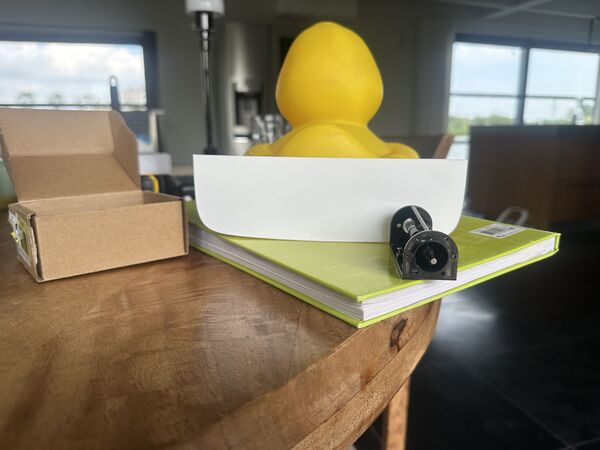
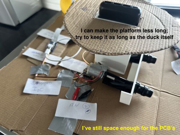
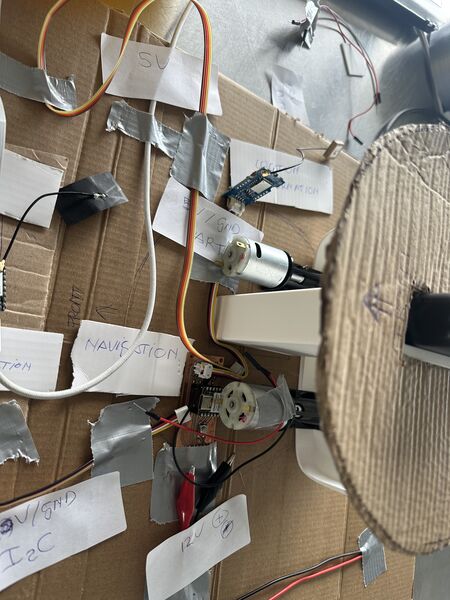
Ok skip it for now, maybe I need visual examples to help me model it. I therefore took some carton and draw the duck on top of it and positioned the power bank and the 2 motors.
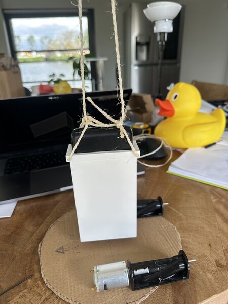
finding the center of gravity for the power bank holder
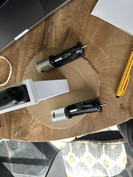
put the motors near the center of gravity as well
Ok at least this gives me more of an idea. Let's first finish this weeks assignment then ...
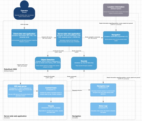
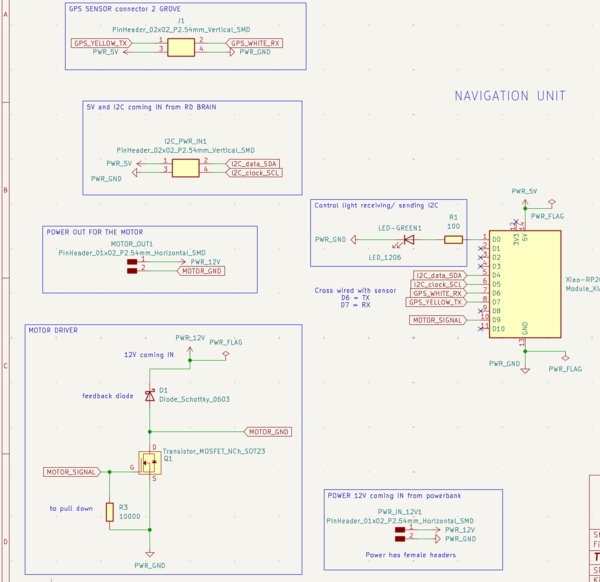
Following my proces I updated my C4-model first; part of my system design.
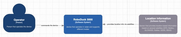
After updating the system's architecture I also rewrote the sub systems and what they should do; including a startup sequence and communication protocol
Then I layed it all out which helped a lot. First thing I found was that the ESP32S3 was directly attached on the Grove AI module. So this means that getting another connection to the outside means I need to find a solution = I have to create a PCB for it.
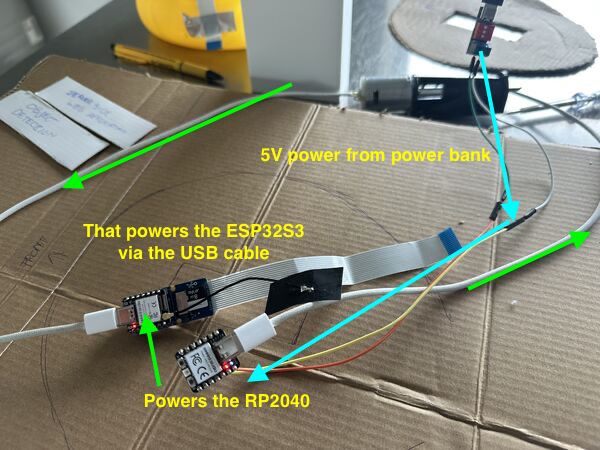
I tried to connect RP2040 and the ESP32S3 via USB and power the RP2040. The ESP32S3 actually got power as well
So that's nice, I can just communicate Serial via USB between the ESP32S3 and the RP2040. Just like with my computer right?
Well the internet is a bit grumpy. It's a bit more complicated apparantly than I thought at the moment. Probably not that difficult but for the moment stick to what I know. I'll therefore use a seperate PCB on which the ESP32S3 gets power from the power bank and provides power to the navigation module (via a special cable with 5V, GND aand I2C) and interacts ith the vision AI module via UART.
Smaller camera has been ordered. For the light I want to use a neo-pixel.
The RP2040 gives power to the 12V DC motors and gets its own 5V power from the ESP32S3 (including I2C)
Grove - ESP32S3 two RP2040
I wanted to know more about serial via USB and soon came across the term USB CDC. And from thereon I dove into a small rabbit hole from the maker of the ESP32 series. So yes, I probably can do this. Meaning power the ESP32S3 via a USB cable connected to a RP2040. BUT ... this means another library and diving into new technology that I don't know yet. Hmmmm ...
Then I took another look at what was right in front of me. When I stick the ESP32S3 on top of the Grove AI module pinout I can use the standard grove cable (red, black, white and yellow) to power the RP2040 and communicate via I2C. For this I did a small test using an older PCB that I hard wired to the red/black from the grove cable and yes and lit up.
Note
According to this article the cable provied 3V3, GND and I2C. And according to SeeedStudio info about the RP2040 the 5V input is actually converted to 3V3 for operation. So no problems here at the moment.
So I updated the mockup
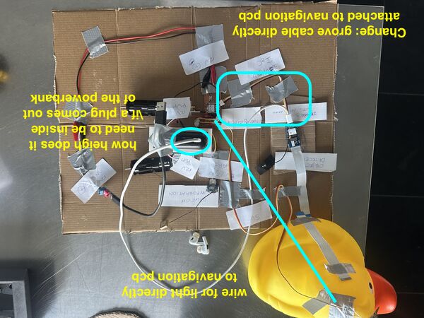
This means I now have to design/mill 1 PCB for navigation.
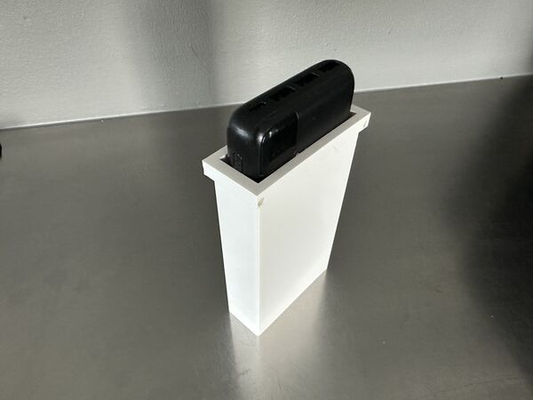
And I checked the required height inside the platform.
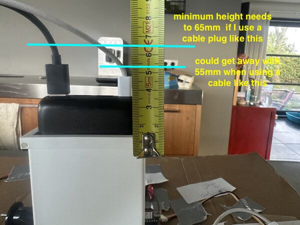
so when the power bank sticks out inside and you put a cable into it I need at least 55mm height inside. That is using the cables I have.
Storing images
Another question I had was how I could use the AI module to store images. I know I can use the invoke command and set a parameter to true. But then it only safes an images when the invocation was successful.
Well yes and no. I can set the treshold ... so I could say when it's 20% a person than save the image. I can use this command once as a trigger or I can use an AT-command.
More info about the files can be found here.
For my scope this means that I will NOT support just taking images; like a cam-recorder
Day 7 - [Tuesday]
Yet another day in Zamunda (quote from Eddie Murphy's movie Coming to America). I use it to start the day with a smile. In Dutch we would say I started again "met goede moed. I first sat down and thought again about how to draw the openings for the waterjet at the back and below.
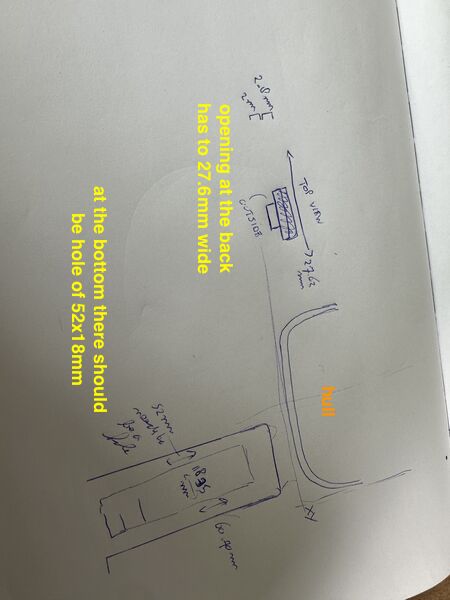
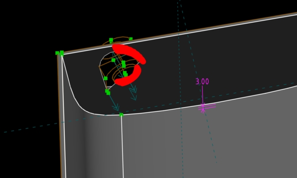
Even cut it in the hull I created a couple of days ago.
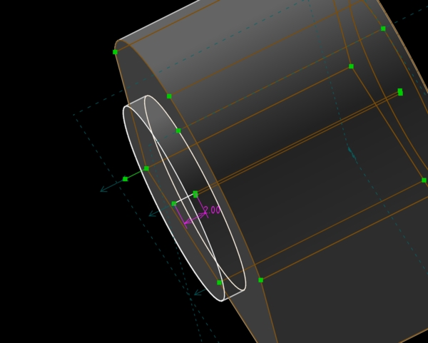
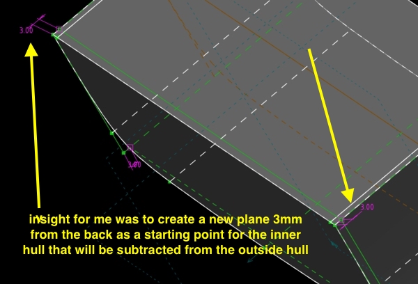
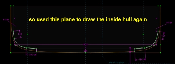
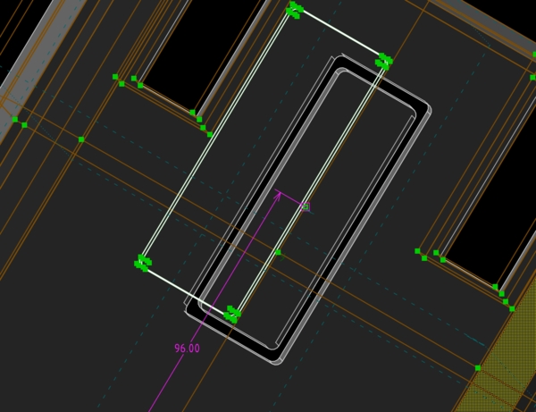
I can just start a new plane using a point and 2 line segments from that point. So I created these 3mm from the back of the outer hull ..
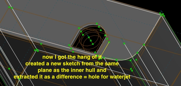
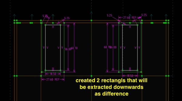
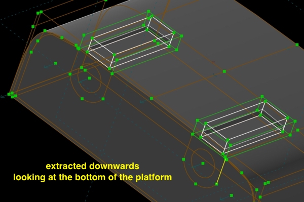
Then onto the openings = water intake at the bottom
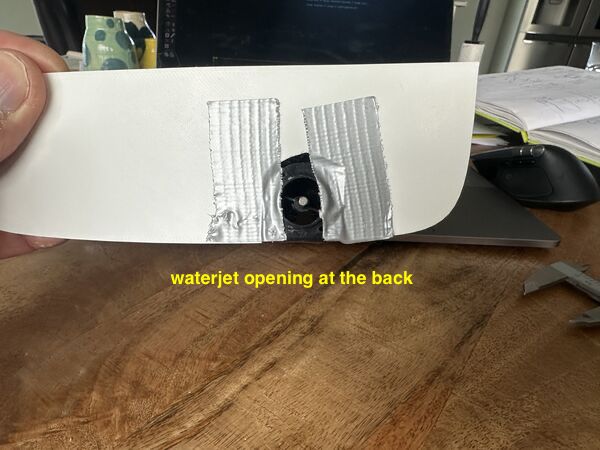
See what PrusaSlicer thinks of it
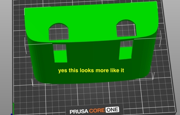
So how does it fit?
I'm very happy with this ... just a small tweak is needed.
So I put it into perspective of my mockup
Ok let's make room for the battery holder
adding it as assembly but it's difficult to position because it keeps floating in 3D
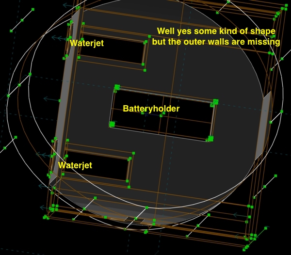
So I decide to just create the hole again; don't have to model everything of course because the batteryholder has it's own design
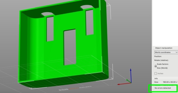
PrusaSlicer does not object; no errors detected
To get of the box I wanted to make it more like the duck's shape.
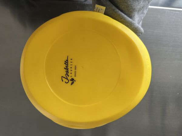
I took a picture from the bottom of the duck
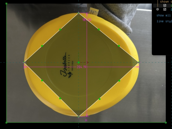
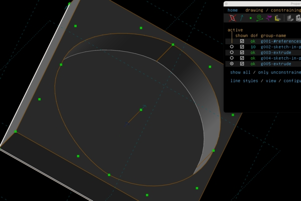
then imported it into Solvespace
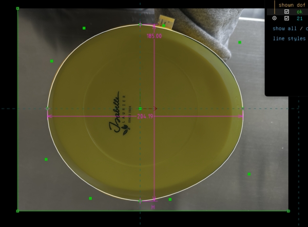
sketch the contour in 2D
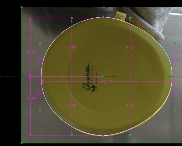
match it with the measurements of the duck itself
my idea is to extrude this shape and use it with a boolean operator in the hull's design to keep everything I had and just cut of the edges in the shape of the duck
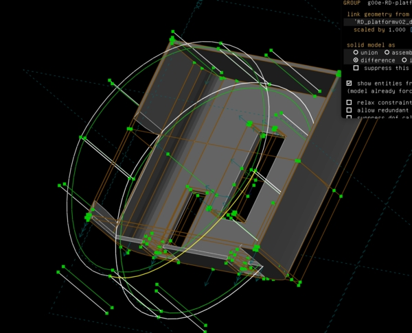
nice idea but it's doesn't work
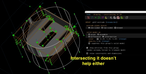
intersection ... nope
and again nope
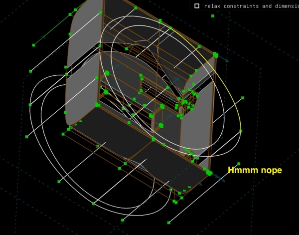
So I decided not to use an import of that object of the duck and draw something similar inside the design I already had; as a new sketch.
new sketch using some of the duck's outer measurements
I'm not getting were I want
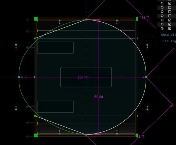
Decided to skip this and try using an outer ring and then wrap this around it
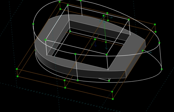
this looks ok but now I want the holder and water added to this
but first a bottom
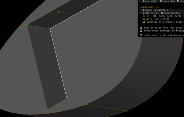
doing an in between exercise; try out; my idea should work
intersect this the object; and nope
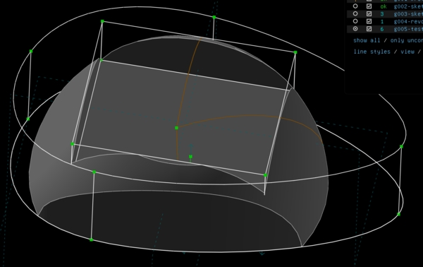
create a new base object
and again this is not working
So basically it took me 6 hours after having a based hull with holes for the jets and the batteryholder to getting no further at all. This is at least frustrating. I gave up for now; I need to get something done today.
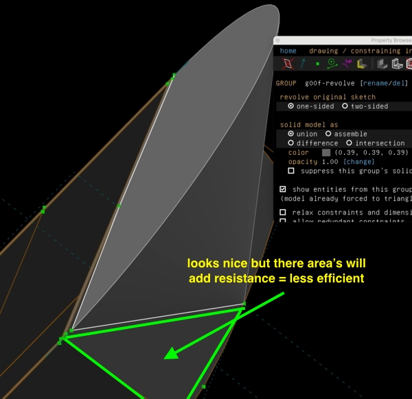
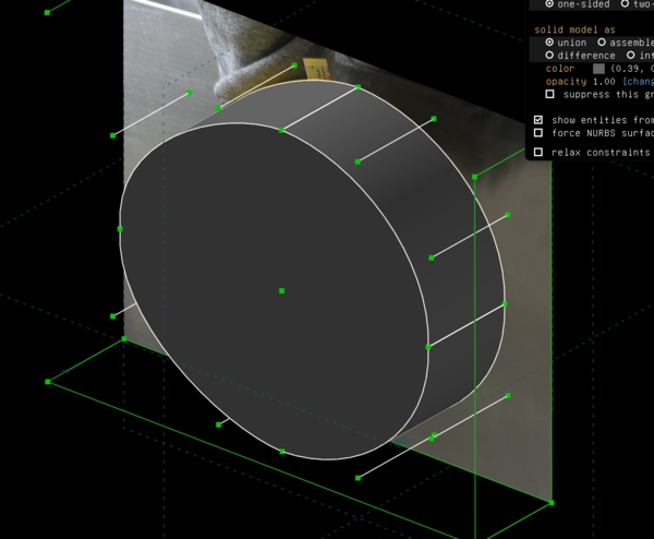
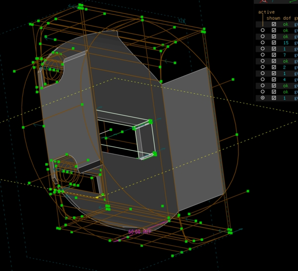
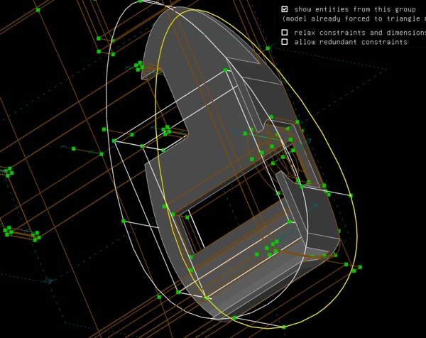
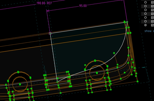
used a revolve around a 2D shape to add a piece of hull in the front
use a smoother shape maybe that is also lower
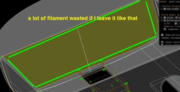
but now I'm left with these enormous blobs
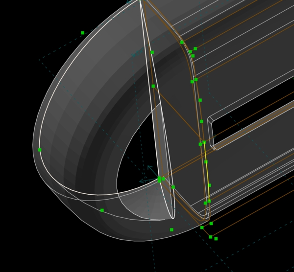
use a revolve from the inside to make it hollow
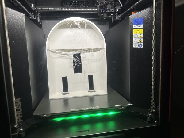
I finally ended up with this design.
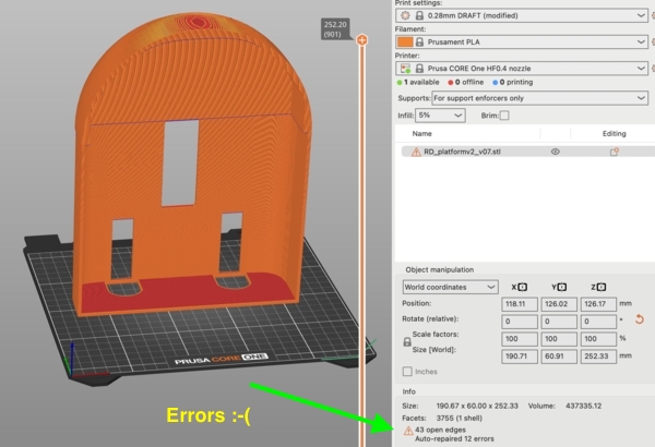
PrusaSlicer was ok but no too happy as there were errors to fix. This matcht a message in SolveSpace about self intersecting areas which I was too tired to find and fix
So before I went to bed the printer was working on it
Day 8 - [Wednesday]
Updating my documentation from yesterday first.
During the night I went out to look at the 3D print of the hull (which took nearly 4 hours)
the printer made it ... wauw
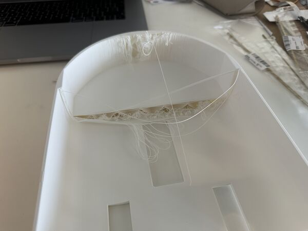
so overhang issues; clearly
BOM
Global class pointed to a plugin for KiCad to generate your BOM based on a schema. Happily I could just install it via the option Tools - Plugin and Content manager.
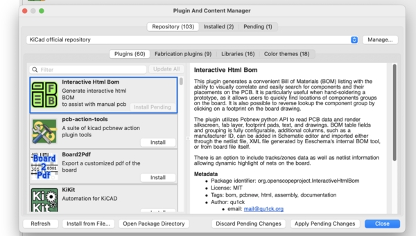
find it by name and install it
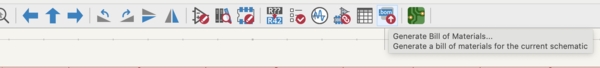
use the little button to activate the plugin
The exported CSV file was put in the same directory as the Kicad files. From there I used this website to convert the CSV file to Markdown table
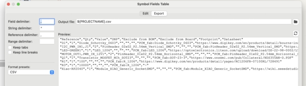
CSV file
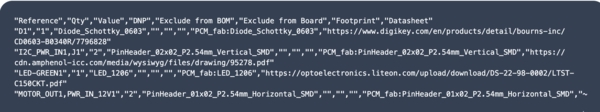
content of the CSV file imported
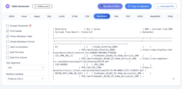
presented as a markdown table
I uploaded this first version to my BOM
Note
While using mkdocs build command to check my documentation layout I got
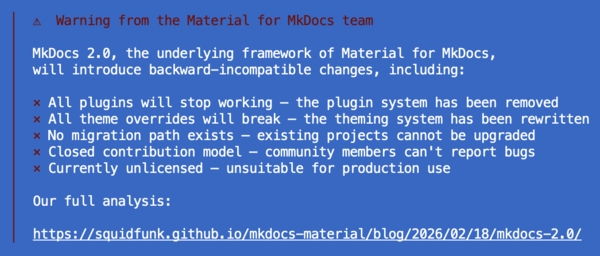
But I'm using v1.6 so I should not get a problem.
Files for download / replication
As everything I did is linked to my final project I made the updates there (like the BOM).
This archive contains the latest C4-model and design of the overall hull and batteryholder.
Problems & Solutions
SolveSpace’s boolean operations and geometry tools cost me many hours with self-intersecting sketches and floating parts. I tried to solve it by starting from the outside in, using simpler reference sketches, and printing separate test pieces for critical features. I have a hull but I'm not yet happy with it.
I printed a nice battery holder ring only to discover it had no floor. I quickly added a 3 mm bottom with rounded edges and reprinted it the same evening.
The printer works beautifully but I had some issues with knotted filament which caused a print to continue 5 mm too high. I cleaned the extruder, unwind the tanglment and just retried it.
Internal height was tight with a first version of the power bank and outcoming connectors. I lowered the battery keel and planned proper side routing for strain relief and protection against loosing the battery all together.
I also overcomplicated the architecture with an extra ESP32-C6. The mockup helped me see that I could use the Grove cable from the combo ESP32-S3 - AI module as power and I2C connection to the RP2040. This saved a PCB.
Reflections & Learnings
What Went Well
- The C4 diagrams gave me clarity and helped me spot unnecessary complexity (dropping the extra ESP32-C6 saved a PCB and possible headaches).
- Cardboard mock-ups and quick SolveSpace tryouts helped me discover centre-of-gravity and height issues before wasting filament. Also gave me more insight into the 3D aspects of the overall placement of things
- Real-world testing of the water-jet (even at 6 V) gave me confidence that the propulsion concept works
- Trying to take a step back and see the forest; draw were I could
- Although Tuesday was a very frustrating day with 3D design I'm much quicker now and not afraid anymore to use it. I already had ideas to improve my hull design but of course keep the spiral in mind.
What Was Challenging
- Well mainly 3D design like boolean operations and precise positioning in SolveSpace. — I lost several hours on getting a better duck shape and issues with self-intersecting meshes.
- Deciding where to stop iterating on the hull shape versus moving on to electronics integration and "just do this first"
What I Could Improve
- Probably lots of things but I think I took the right steps this time. I should keep watching those rabbit holes though.
Overall lessons
I’m reminded again that being forced to actually put pieces together shows the strenghts and weakness of my design. Not to forget it shows how much more I've to accomplish.
Link to Final Project
Well basically everything.
Acknowledgements
Thanks to Henk and Remco for the local brainstorming sessions and practical suggestions (tunnel/keel ideas, camera mounting angle). And to my family who, despite doing their own things, did see little of me.