This week's assignment was to develop an interface that communicates with input and output devices connected to an embedded board previously built.
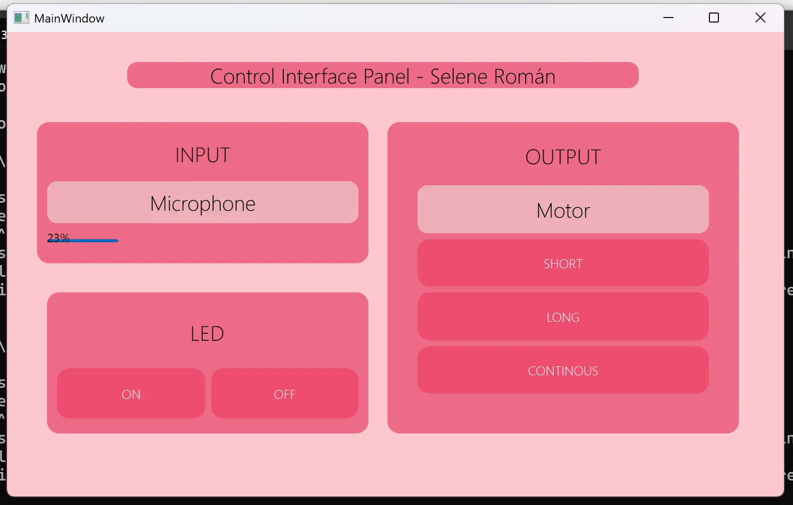
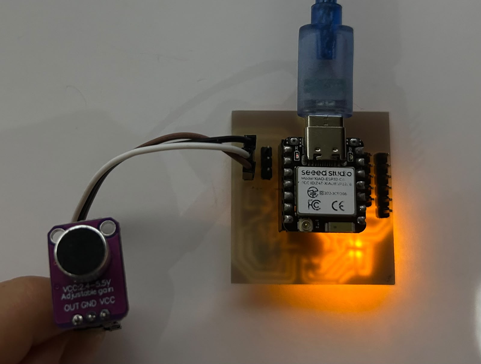
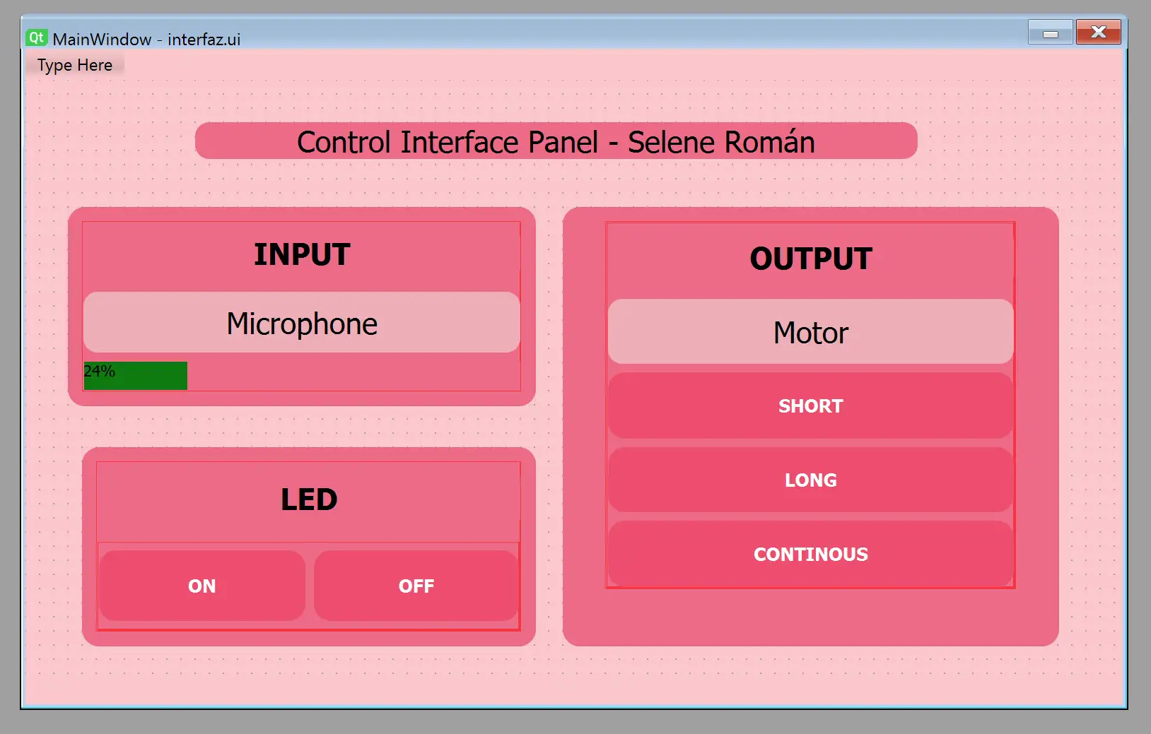
For this week, I decided to create an interface to monitor the noise level detected by my microphone as an input device. As output devices, I implemented control of a vibration motor module with three different vibration modes and added the ability to turn an LED on and off from the interface as a functionality test. I used a testing board that I previously designed and used in Week 11, based on a XIAO ESP32-C6.
Check here the group assignment for this week for more information about interfaces.
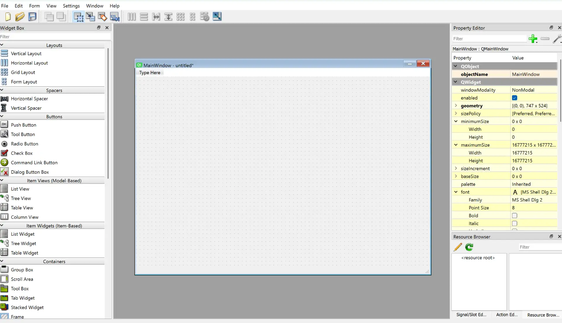
To create the interface, I used Qt Designer. Qt Designer is part of the Qt development ecosystem, a popular cross-platform framework used to develop applications in both C++ and Python through libraries such as PyQt and PySide. It provides a visual environment for designing graphical user interfaces, making it easier to create and organize interface elements without writing the entire layout manually.
The first step is to create a virtual environment on your computer. A virtual environment is an isolated workspace used for software development. It allows a project to have its own libraries, packages, and dependencies without affecting the global Python installation or other projects on the same computer.
python -m venv venvvenv\Scripts\activatepip install pyserial PyQt6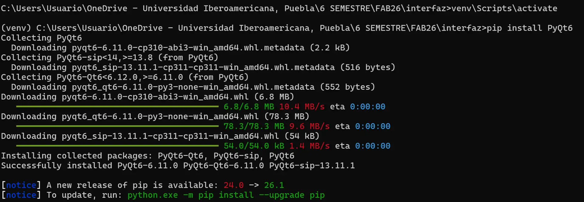
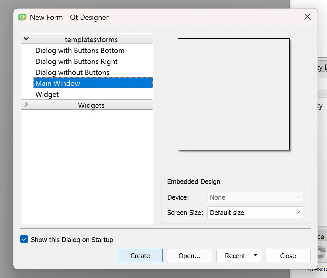
To begin creating the interface, open Qt Designer.
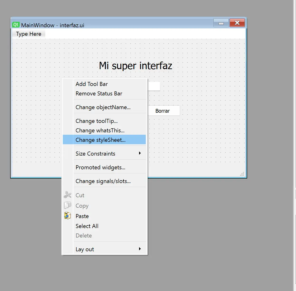
color: Changes the font color.border-radius: Controls the roundness of corners (expressed in pixels).QPushButton:hover: Changes the button appearance when the mouse hovers over it.QPushButton:pressed: Changes the button appearance when it is clicked.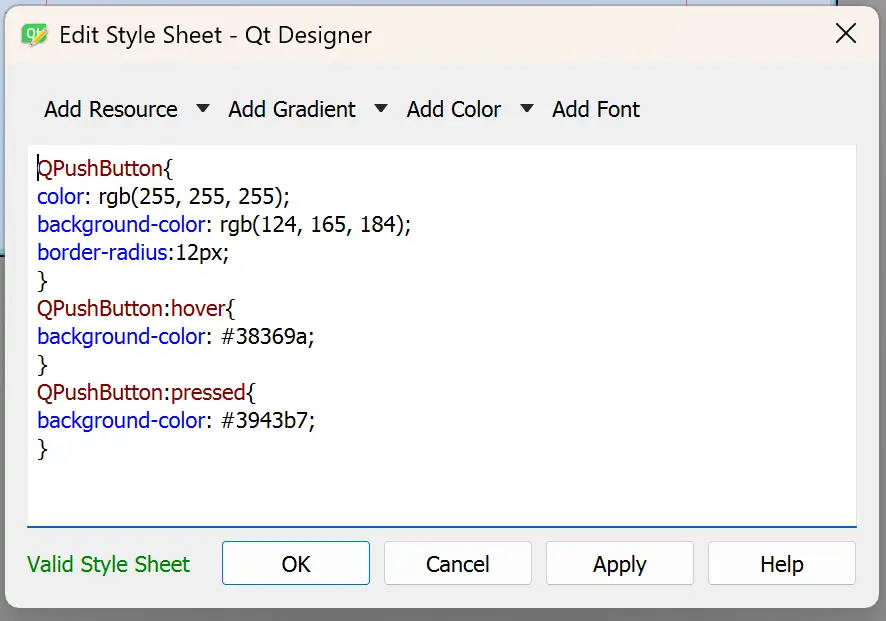
pyuic6 -x interface.ui -o frontend.pyinterface.ui) into a Python file (frontend.py) containing all the code required to recreate the graphical interface within a Python application.
This generated document handled the programming of the interface's visualization. Therefore, we need to create another document which will contain the interface's logic, since the converted file cannot be edited.
This is the main logic file of the interface. From this point, the programming of the application begins.
                from frontend import *

                class MainWindow(QtWidgets.QMainWindow, Ui_MainWindow):
                    def __init__(self, *args, **kwargs):
                        QtWidgets.QMainWindow.__init__(self, *args, **kwargs)
                        self.setupUi(self)

                if __name__ == "__main__":
                    app = QtWidgets.QApplication([])
                    window = MainWindow()
                    window.show()
                    app.exec()
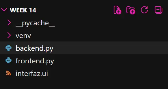
This is how your project folder should look, containing the virtual environment, the .ui file, and the two .py files.
Upload the Arduino code to your board to handle the logic of the input and output devices. To run the interface, execute the following command in the terminal:
python backend.py
The board will communicate with the interface through the COM port, allowing the application to send commands and receive data in real time.
                # Import the serial library used to communicate
                # with the ESP32-C6 through the COM port
                import serial

                # Import PyQt6 modules for the graphical interface
                from PyQt6 import QtWidgets, QtCore

                # Import the interface generated from Qt Designer
                from frontend import *

                # Main application window
                class MainWindow(QtWidgets.QMainWindow, Ui_MainWindow):

                    def __init__(self):

                        # Initialize the parent class
                        super().__init__()

                        # Load the graphical interface
                        self.setupUi(self)

                        # Store the currently selected motor mode
                        self.motor_actual = None

                        # Open serial communication with the ESP32-C6
                        self.esp = serial.Serial(
                            'COM3',      # COM port used by the ESP32-C6
                            115200,      # Communication speed
                            timeout=0.1
                        )

                        # LED control buttons
                        self.button_on.clicked.connect(self.led_on)
                        self.button_off.clicked.connect(self.led_off)

                        # Motor control buttons
                        self.button_short.clicked.connect(
                            lambda: self.motor_toggle("SHORT")
                        )

                        self.button_long.clicked.connect(
                            lambda: self.motor_toggle("LONG")
                        )

                        self.button_cont.clicked.connect(
                            lambda: self.motor_toggle("CONT")
                        )

                        # Create a timer that continuously checks
                        # incoming serial data from the ESP32
                        self.timer = QtCore.QTimer()

                        self.timer.timeout.connect(
                            self.leer_serial
                        )

                        # Execute every 50 milliseconds
                        self.timer.start(50)

                    def led_on(self):

                        # Send command to turn the LED on
                        self.esp.write(b"LED_ON\n")

                    def led_off(self):

                        # Send command to turn the LED off
                        self.esp.write(b"LED_OFF\n")

                    def motor_toggle(self, modo):

                        # If the selected mode is already active,
                        # turn the motor off
                        if self.motor_actual == modo:

                            self.esp.write(b"MOTOR_OFF\n")

                            self.motor_actual = None

                        else:

                            # Send the selected motor mode
                            self.esp.write(
                                (modo + "\n").encode()
                            )

                            self.motor_actual = modo

                    def leer_serial(self):

                        # Check if serial data is available
                        while self.esp.in_waiting:

                            # Read one line of data
                            linea = self.esp.readline().decode(
                                errors='ignore'
                            ).strip()

                            # Look for microphone values
                            if linea.startswith("MIC:"):

                                # Extract the numeric value
                                valor = int(
                                    linea.replace("MIC:", "")
                                )

                                # Update the progress bar
                                self.micro.setValue(valor)

                if __name__ == "__main__":

                    # Create the Qt application
                    app = QtWidgets.QApplication([])

                    # Create and show the main window
                    window = MainWindow()

                    window.show()

                    # Start the event loop
                    app.exec()
                // LED connected to pin D2
                #define LED_PIN   D2

                // Vibration motor connected to pin D0
                #define MOTOR_PIN D0

                // Microphone connected to analog pin D1
                #define MIC_PIN   D1

                // Variable used to store incoming serial commands
                String comando = "";

                // Enumeration used to define the available
                // vibration modes for the motor
                enum MotorMode {

                MOTOR_OFF,    // Motor disabled
                MOTOR_SHORT,  // Three short pulses
                MOTOR_LONG,   // Three long pulses
                MOTOR_CONT    // Continuous vibration
                };

                // Store the current motor state
                MotorMode motorMode = MOTOR_OFF;

                void setup() {

                // Initialize serial communication at 115200 baud
                Serial.begin(115200);

                // Configure LED and motor pins as outputs
                pinMode(LED_PIN, OUTPUT);
                pinMode(MOTOR_PIN, OUTPUT);

                // Ensure both devices start turned off
                digitalWrite(LED_PIN, LOW);
                digitalWrite(MOTOR_PIN, LOW);

                // Configure ADC resolution to 12 bits
                analogReadResolution(12);
                }

                void loop() {

                // Read commands coming from the Python interface
                while (Serial.available()) {

                    char c = Serial.read();

                    // A complete command is received when a
                    // newline character is detected
                    if (c == '\n') {

                    comando.trim();

                    // Turn LED ON
                    if (comando == "LED_ON") {
                        digitalWrite(LED_PIN, HIGH);
                    }

                    // Turn LED OFF
                    else if (comando == "LED_OFF") {
                        digitalWrite(LED_PIN, LOW);
                    }

                    // Activate short vibration pattern
                    else if (comando == "SHORT") {
                        motorMode = MOTOR_SHORT;
                    }

                    // Activate long vibration pattern
                    else if (comando == "LONG") {
                        motorMode = MOTOR_LONG;
                    }

                    // Activate continuous vibration pattern
                    else if (comando == "CONT") {
                        motorMode = MOTOR_CONT;
                    }

                    // Stop the motor immediately
                    else if (comando == "MOTOR_OFF") {

                        motorMode = MOTOR_OFF;
                        digitalWrite(MOTOR_PIN, LOW);
                    }

                    // Clear command buffer
                    comando = "";
                    }

                    else {

                    // Build the command string character by character
                    comando += c;
                    }
                }
            }
                // Variables used to find the minimum and
                // maximum microphone values
                int minimo = 4095;
                int maximo = 0;

                // Measure microphone activity for 50 ms
                unsigned long inicio = millis();

                while (millis() - inicio < 50) {

                    int lectura = analogRead(MIC_PIN);

                    if (lectura < minimo)
                    minimo = lectura;

                    if (lectura > maximo)
                    maximo = lectura;
                }

                // Calculate signal amplitude
                int amplitud = maximo - minimo;

                // Convert amplitude into a percentage (0-100)
                int level = map(amplitud, 100, 3200, 0, 100);

                // Keep values within valid limits
                level = constrain(level, 0, 100);

                // Apply a smoothing filter to reduce noise
                static int levelFiltrado = 0;

                levelFiltrado =
                    (levelFiltrado * 8 + level * 2) / 10;

                // Send microphone level to the Python interface
                Serial.print("MIC:");
                Serial.println(levelFiltrado);

                switch (motorMode) {

                    // Three short vibration pulses
                    case MOTOR_SHORT:

                    for (int i = 0; i < 3; i++) {

                        digitalWrite(MOTOR_PIN, HIGH);
                        delay(200);

                        digitalWrite(MOTOR_PIN, LOW);
                        delay(200);
                    }

                    motorMode = MOTOR_OFF;
                    break;

                    // Three long vibration pulses
                    case MOTOR_LONG:

                    for (int i = 0; i < 3; i++) {

                        digitalWrite(MOTOR_PIN, HIGH);
                        delay(1000);

                        digitalWrite(MOTOR_PIN, LOW);
                        delay(500);
                    }

                    motorMode = MOTOR_OFF;
                    break;

                    // Continuous vibration for 3 seconds
                    case MOTOR_CONT:

                    digitalWrite(MOTOR_PIN, HIGH);
                    delay(3000);

                    digitalWrite(MOTOR_PIN, LOW);

                    motorMode = MOTOR_OFF;
                    break;

                    // Motor disabled
                    case MOTOR_OFF:

                    digitalWrite(MOTOR_PIN, LOW);
                    break;
                }

                // Small delay before repeating the loop
                delay(50);