The objective for this week was to make and test a microcontroller development board that you designed. This involved creating a PCB using one of the various methods available in our laboratory: milling with the Roland SRM-20, laser engraving with the xTool F1 Ultra, or using a vinyl cutter with the Brother machine.
For this task, I used the multipurpose PCB that I previously designed in week 6. I chose to work with the Roland SRM-20 because PCB milling is an excellent technique; this machine is capable of handling all the necessary processes: engraving the traces, drilling the holes, and cutting the board shape. Additionally, I will also demonstrate the creation of a flexible PCB made using the vinyl cutter.
Here is the PCB I previously designed in week 6, in case you want to see a bit of the workflow where I created it. I made some small changes, as I needed to adjust the trace width to 0.5 mm to make it possible to manufacture on the Roland SRM-20.
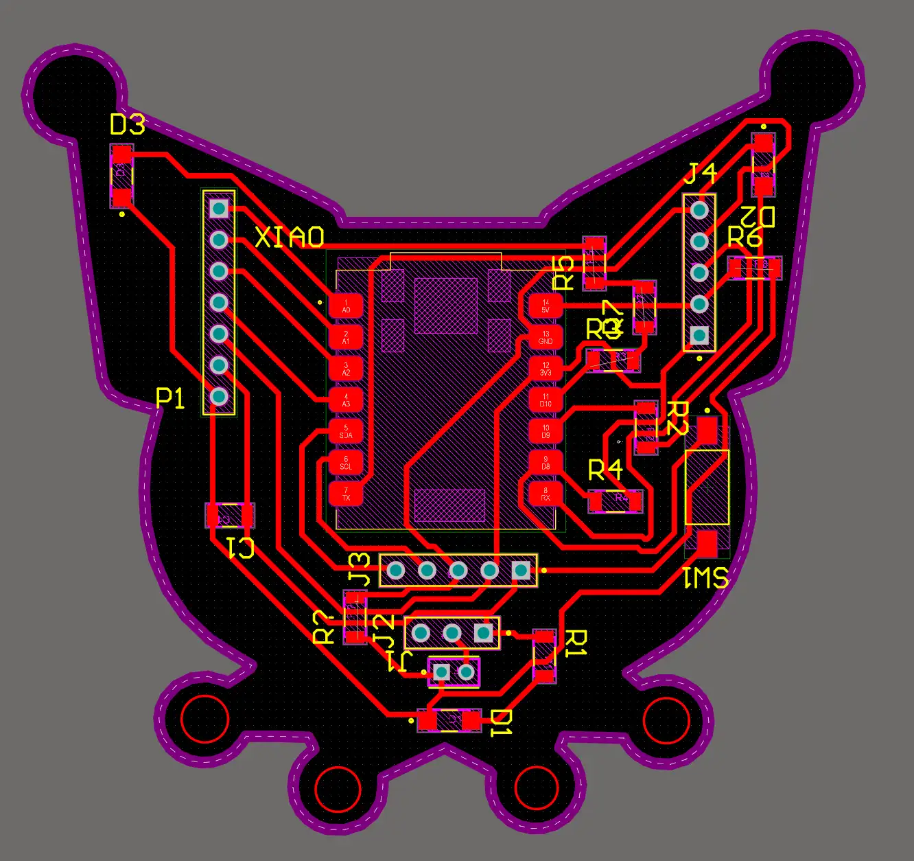 Fig 1. PCB
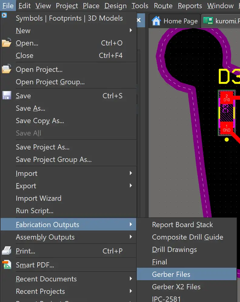
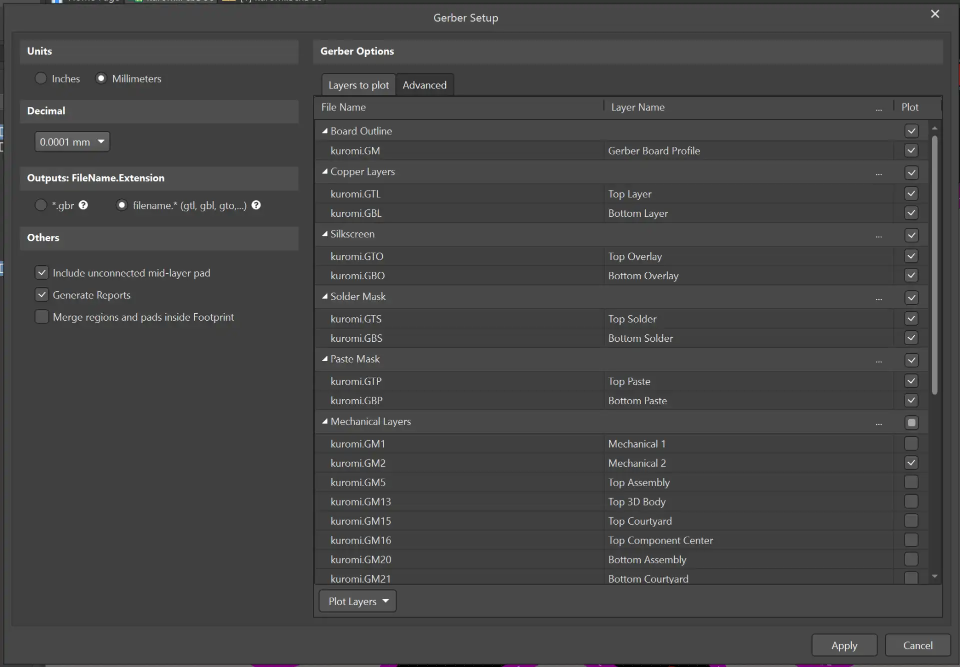
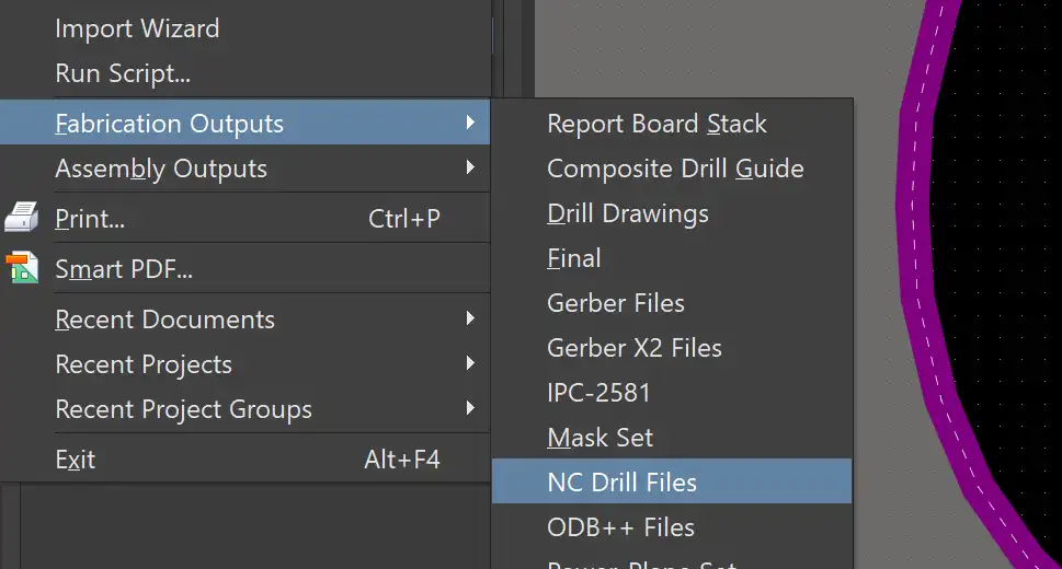
To generate the manufacturing documents for producing the PCB on the MonoFab, we need to export the Gerber files from the software where the PCB was created. In my case, I use Altium Designer.
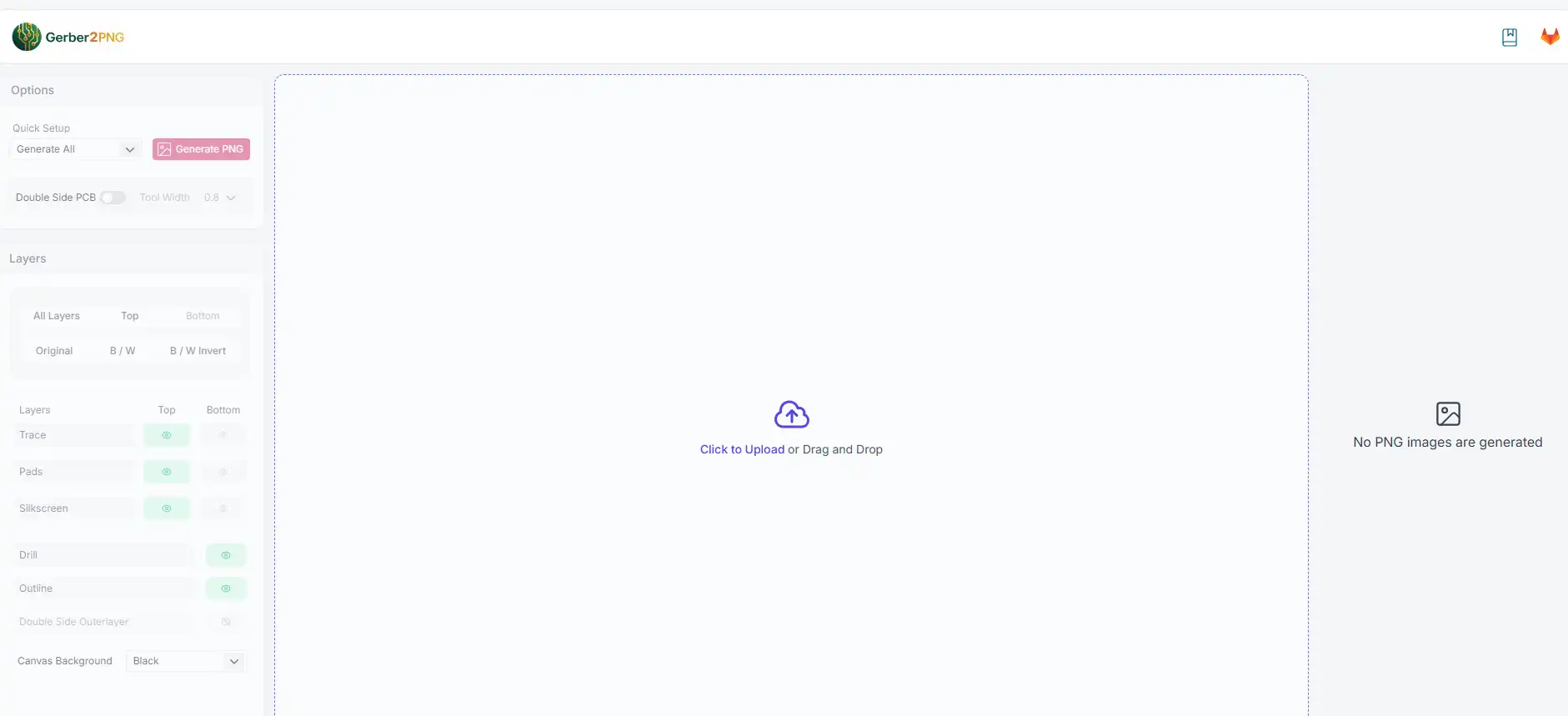
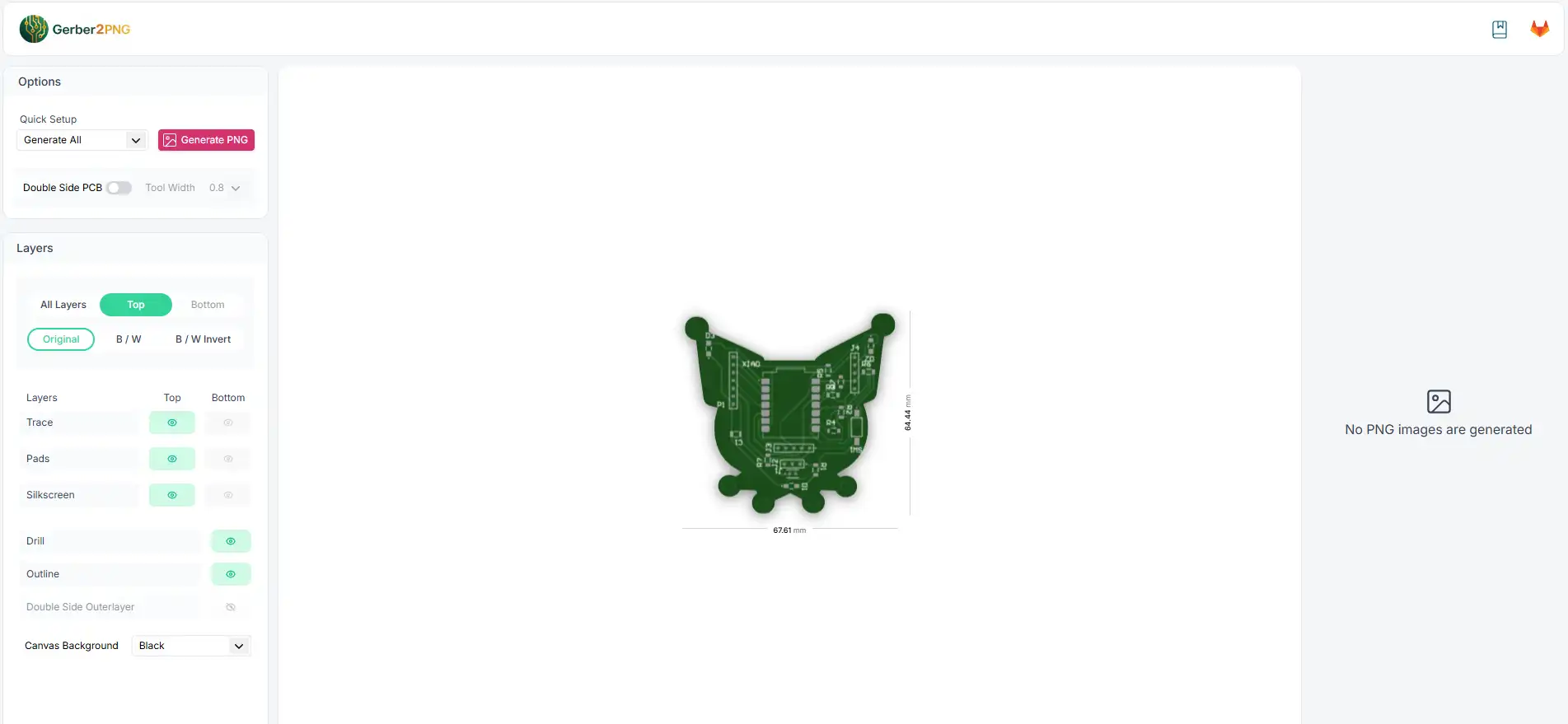
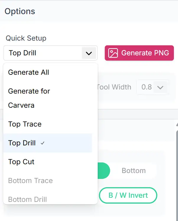
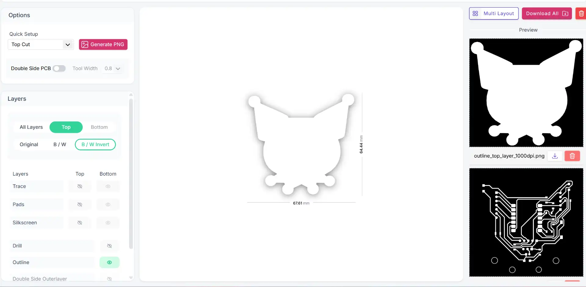
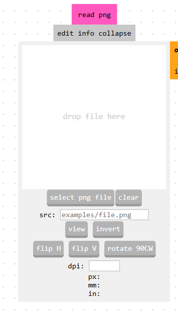
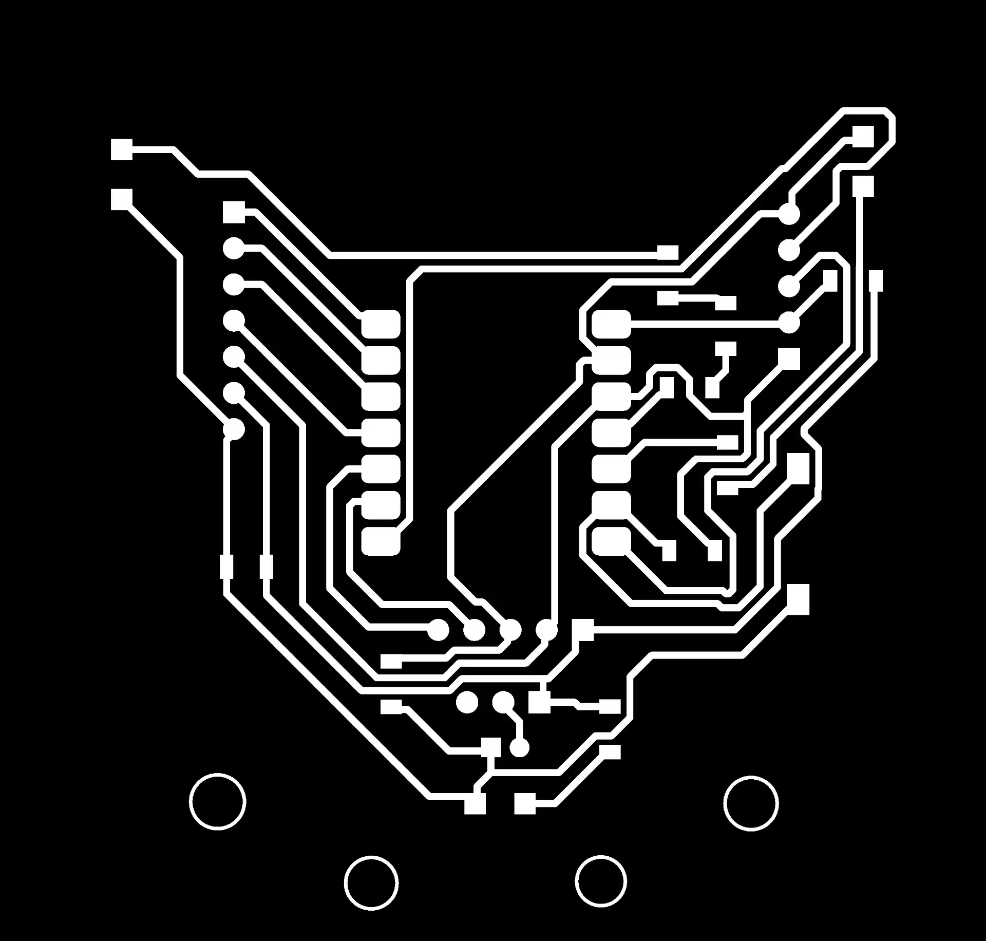
Here are the results of the PNG files I generated.

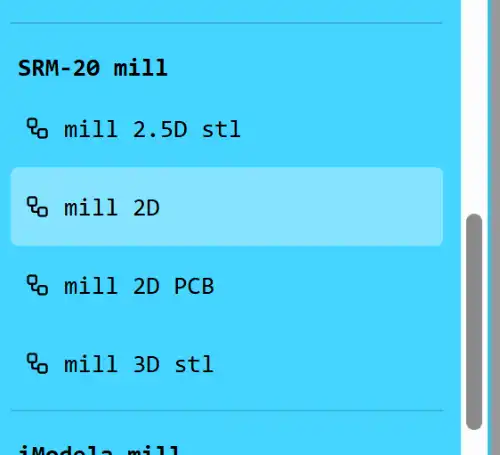
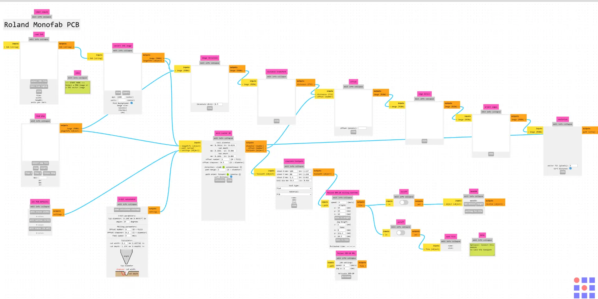
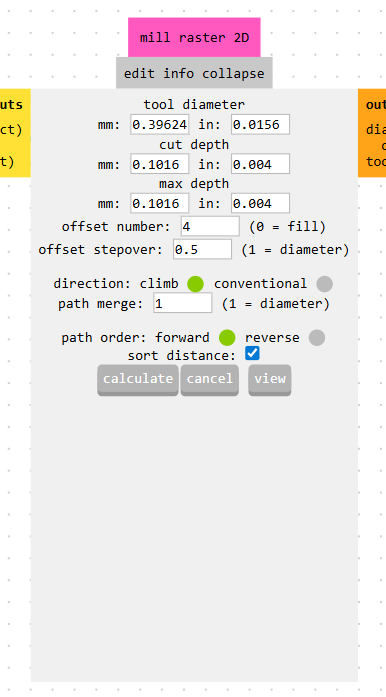
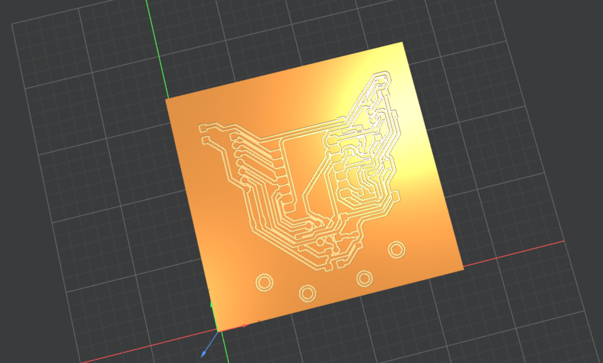
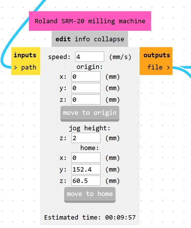
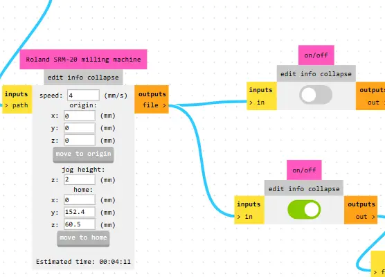
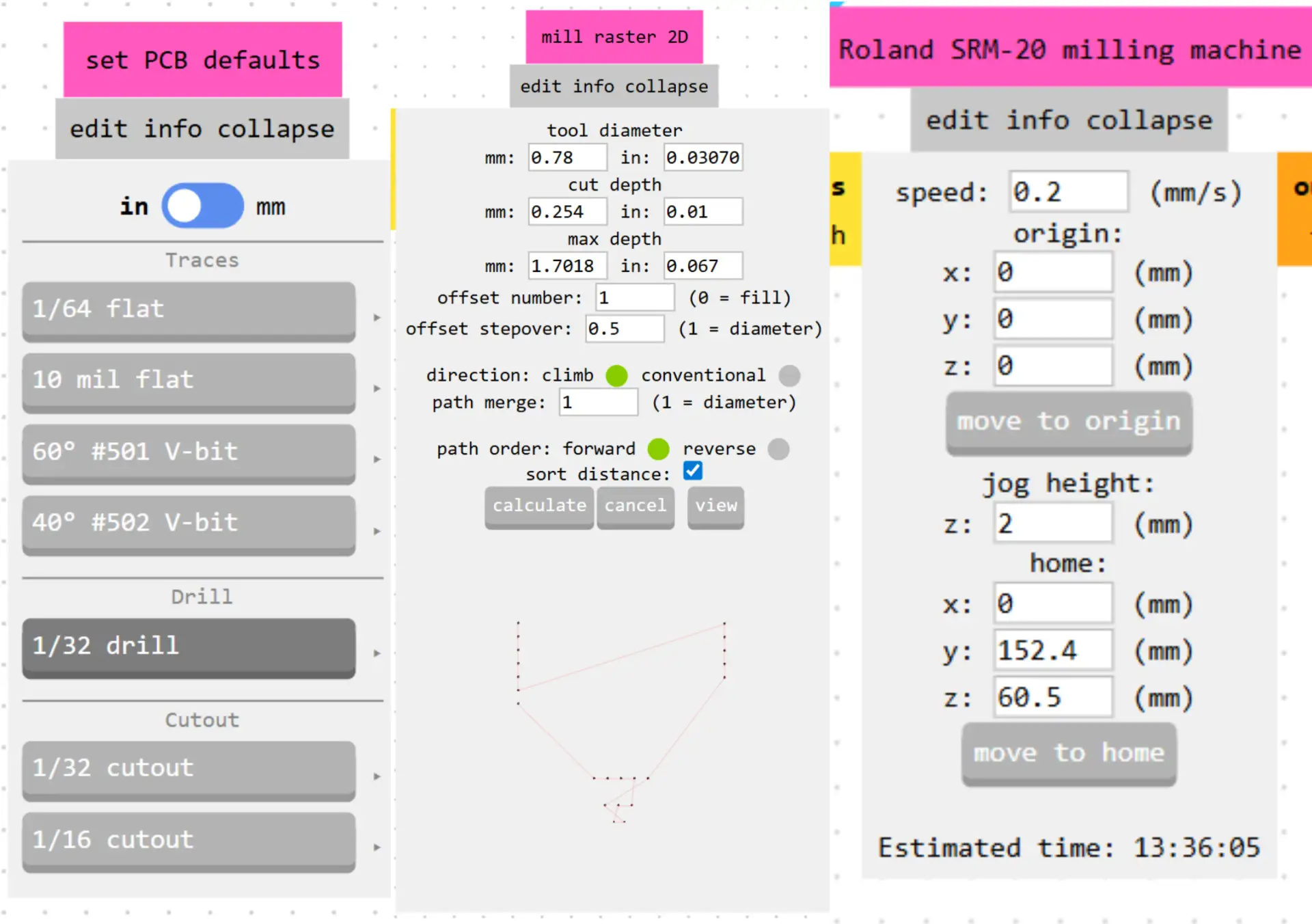
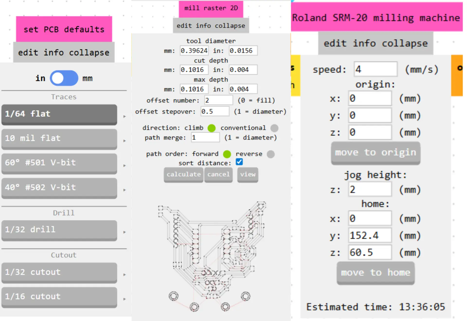
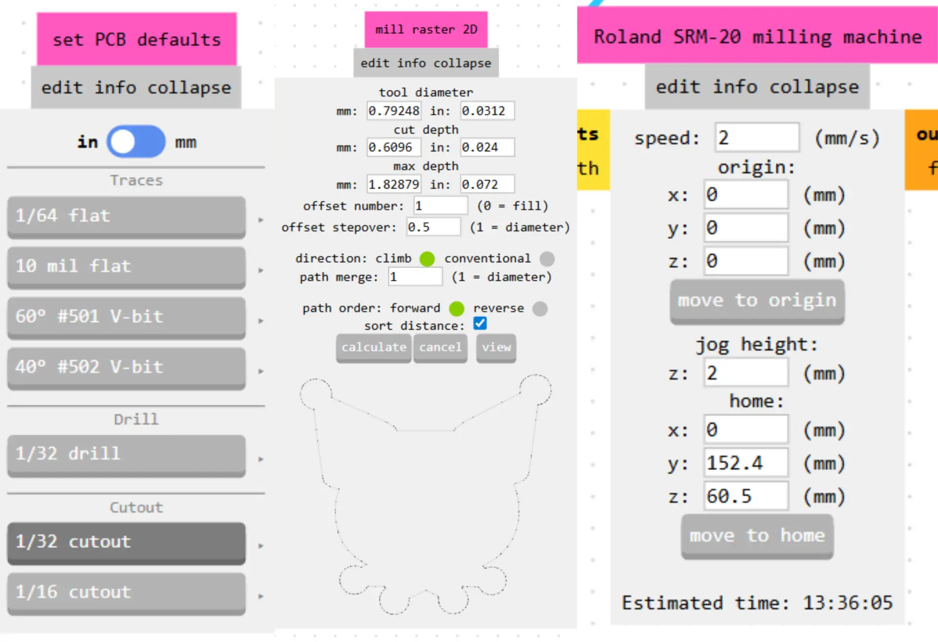
To make our PNG files compatible with the Roland SRM-20, we need to convert them into .rml files. We use the Mods page to process the images and generate the toolpaths required for the monoFab.
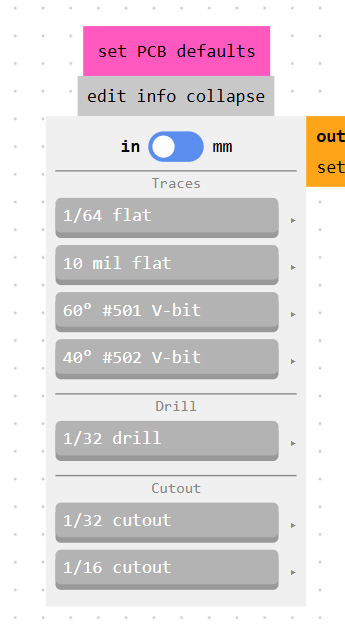
Here are the settings I used for each stage
Once we have generated all the rml files, the next step is to begin the cutting process using VPanel, the software that controls the Roland machine.
This interface lets us move the tool along the X, Y, and Z axes using the on-screen buttons. Once the tool is at the starting point, we use Set Origin Point to save our coordinates. You can also adjust the Cursor Step to control the movement increment.
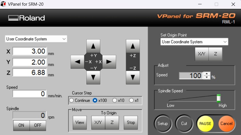 Fig 2. VPanel
After setting the origin for all three axes, we raise the tool to a safe height to avoid collisions. Then, go to the Cut menu and select your file. Simply click the Output button to begin the milling process.
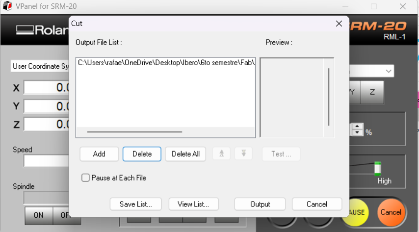 Fig 3. VPanel output
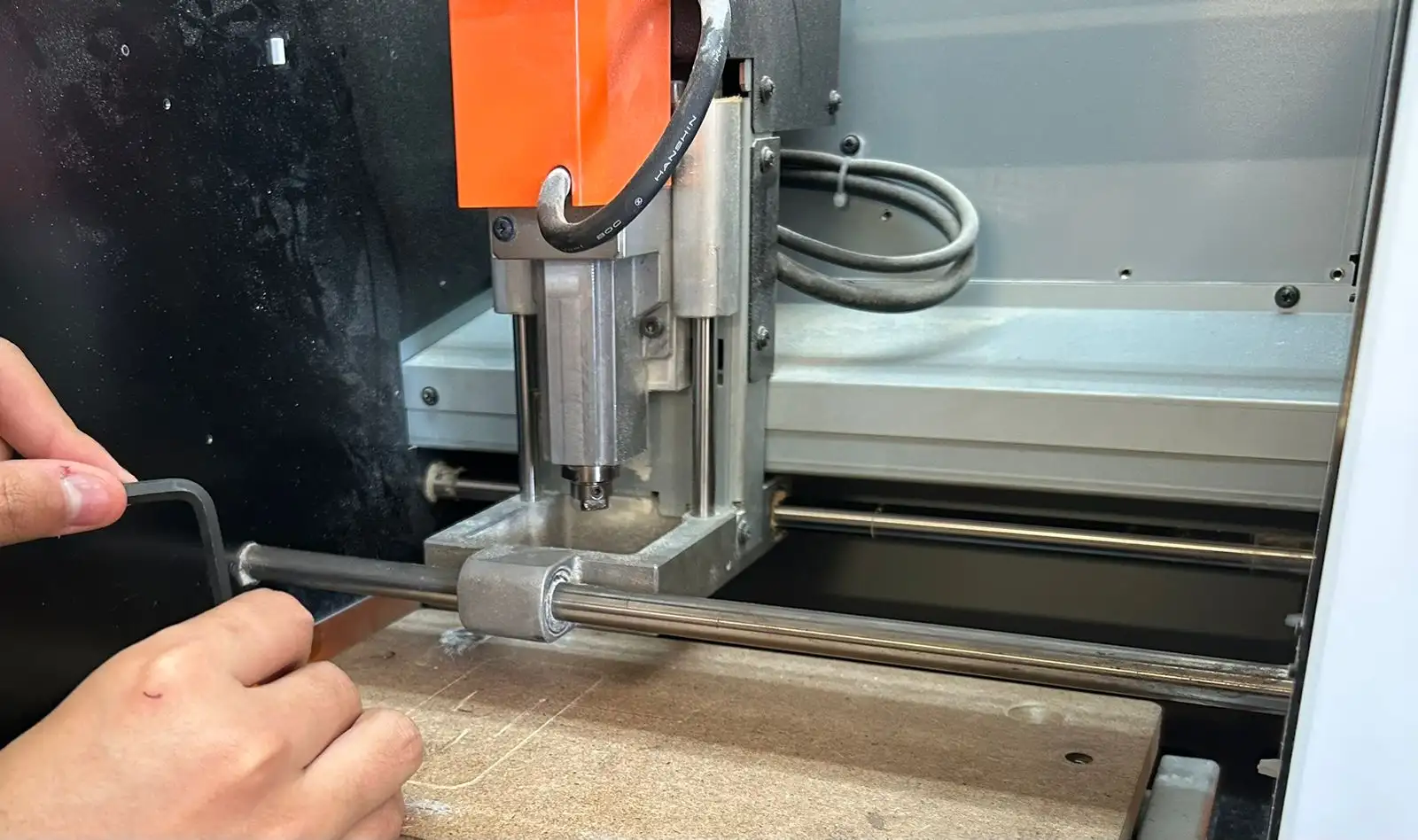
To start the PCB process, we need a sacrifice bed in case the tool cuts through the copper board. We must secure the copper plate to the sacrifice bed using double-sided tape. Make sure the tape covers the entire surface to prevent the board from lifting during the milling process.
These are the tools I used for the PCB fabrication:
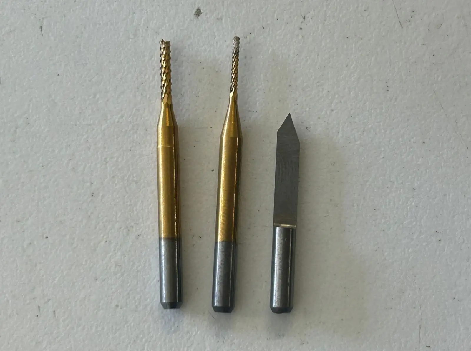
Secure the sacrificial bed in the MonoFab using screws, making sure they are tightened uniformly. A perfectly level surface is essential; any tilt or warping can lead to uneven cutting depths, potentially damaging the traces of the PCB.
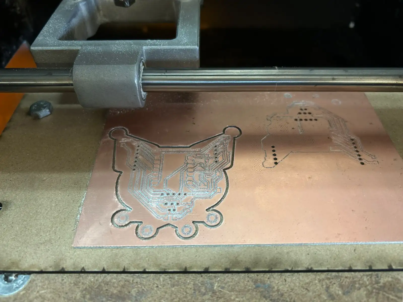
The first step is drilling the holes, as the copper plate is most stable at this stage, allowing for more precision. This is followed by the engraving, and the final step is the outline cut to separate the board.
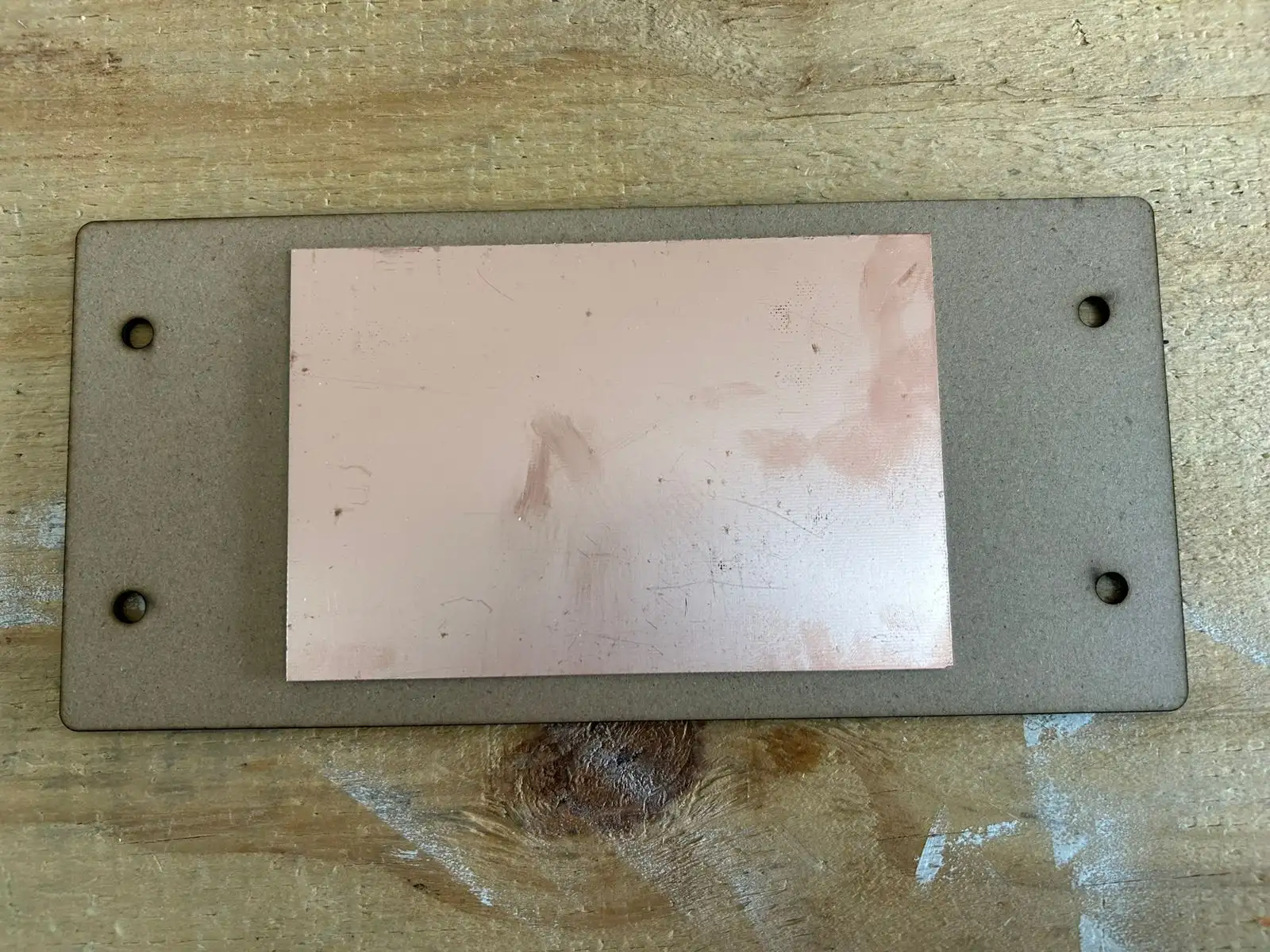
This is how the board looks after all the machine processes are completed.
I used sandpaper to improve the PCB quality because the engraving tool was a bit dull, which left some burrs. Make sure the tools you use are sharp to ensure a much cleaner result from the start.
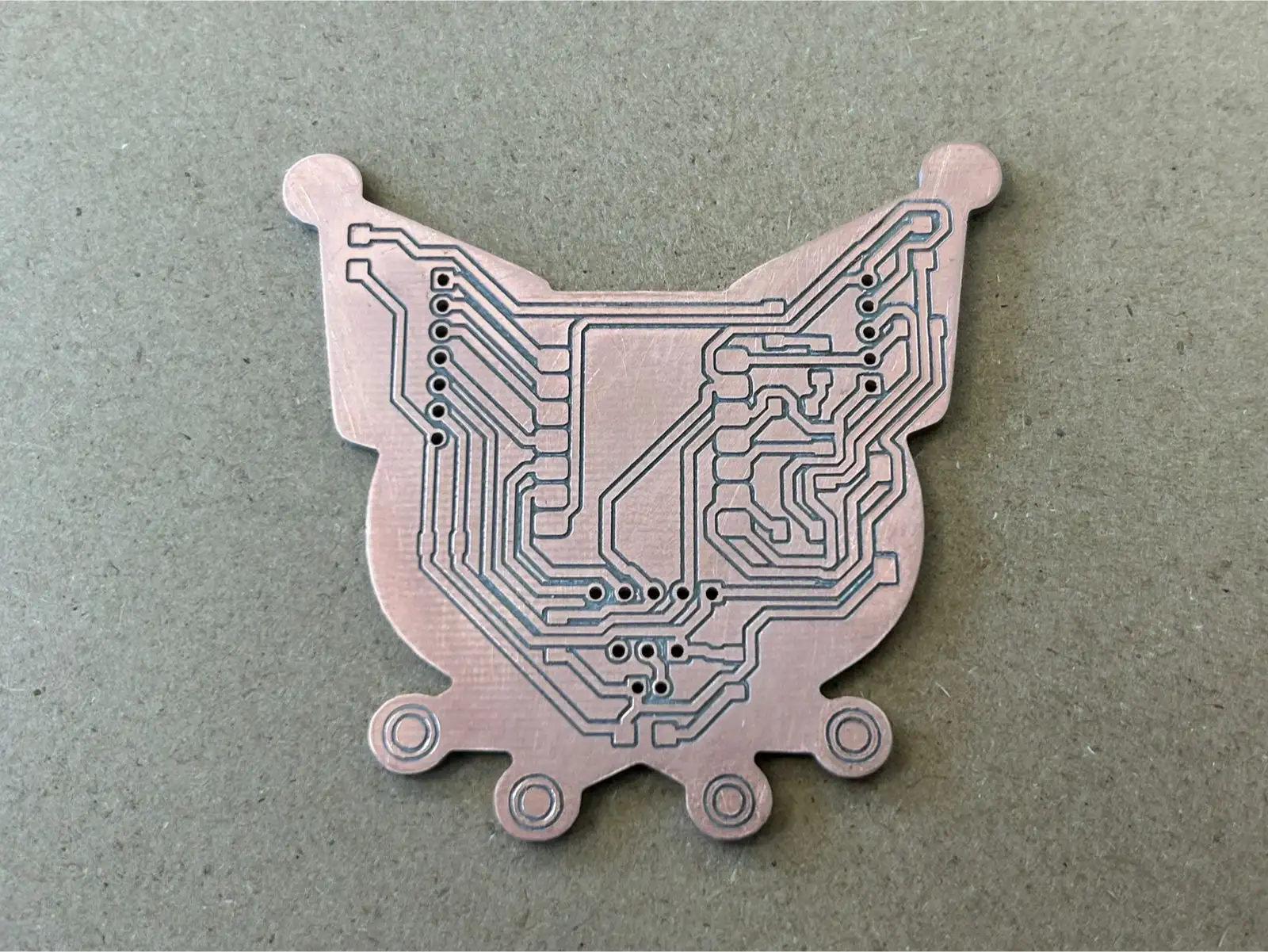 Fig 4. PCB Result
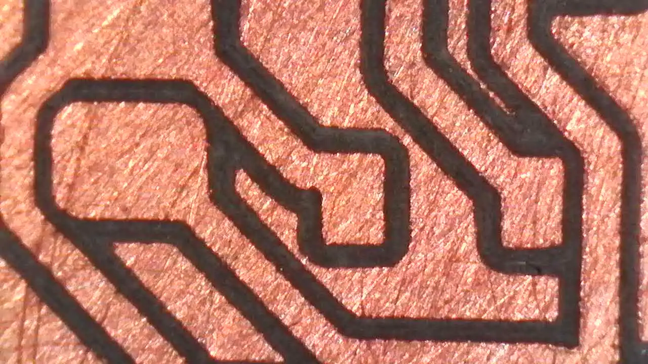
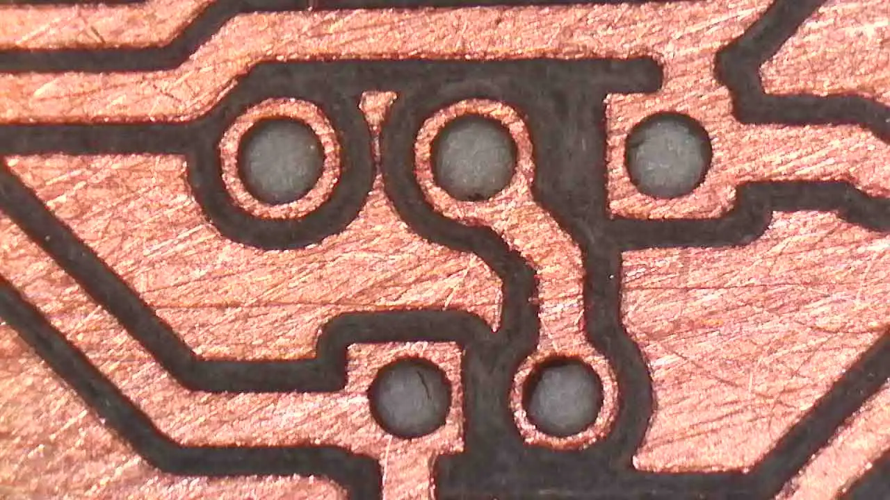
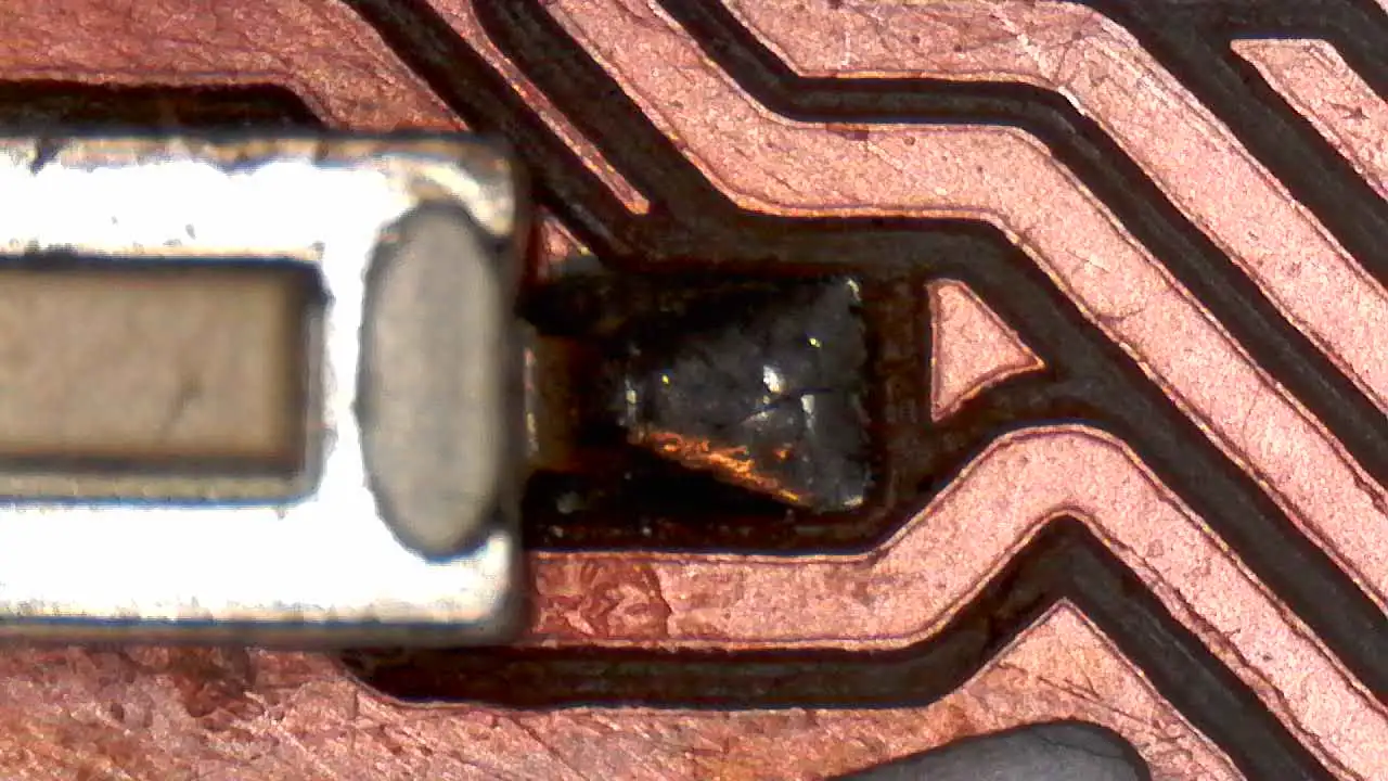
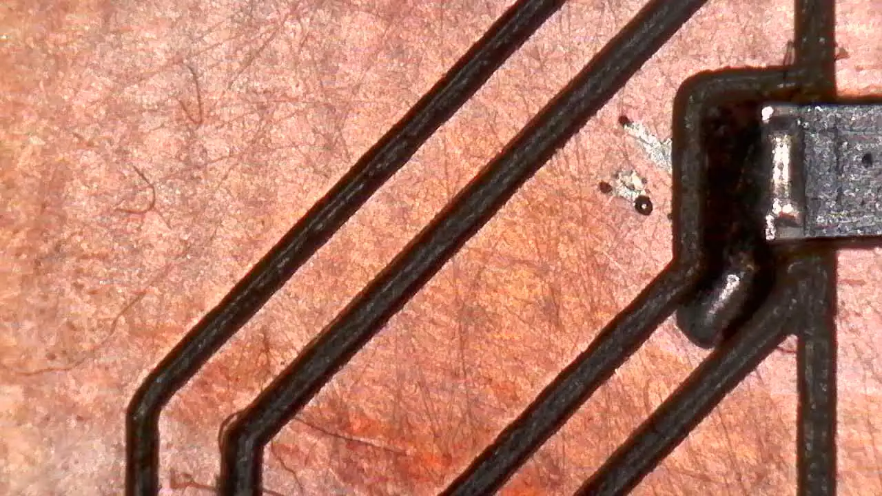
I used a digital microscope to check the quality of the traces and the machine's work in detail.
Once the PCB is manufactured, we move on to the soldering process to assemble all the electronic components. For this project, I used SMD components in the 1206 size.
Components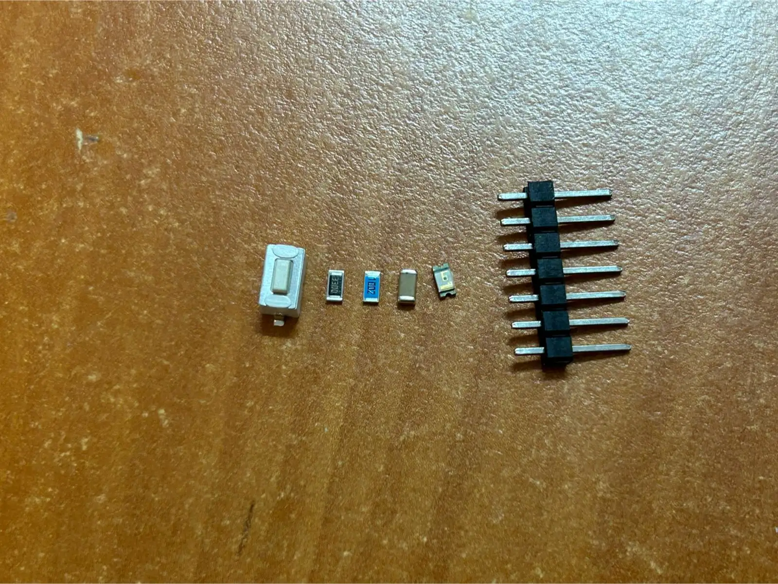
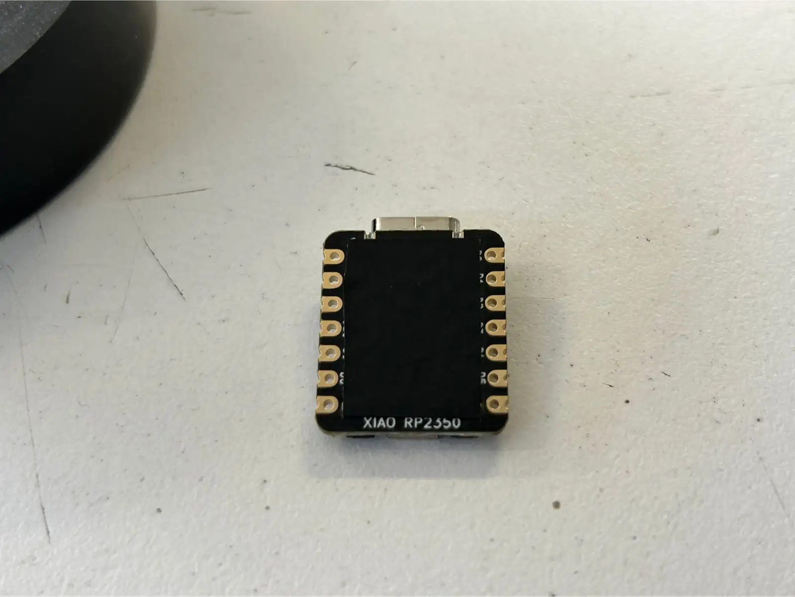
Before soldering the XIAO RP2350, it is crucial to insulate the bottom part of the microcontroller. Since this board has several exposed pads on its underside, they could accidentally touch other parts of the circuit and cause a short circuit. To prevent this, I applied a small piece of tape to the bottom of the XIAO before mounting it.
This is the final result of my soldered PCB.
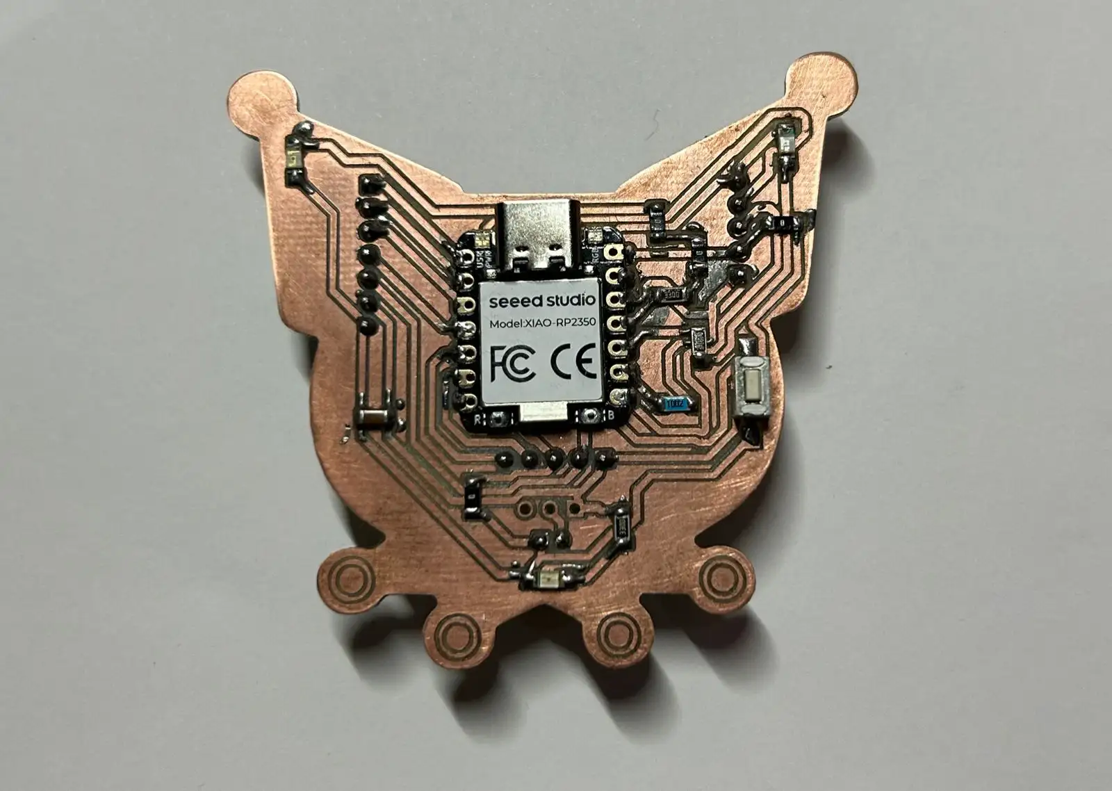 Fig 5. Soldered PCB
Here is a close-up of the solder connections using the digital microscope.
To test the PCB, I used the following simple code to make the LEDs light up when the button is pressed.
                const int botonPin = D8;
                const int led = D9;

                void setup() {
                pinMode(led, OUTPUT);

                pinMode(botonPin, INPUT_PULLUP);

                digitalWrite(led, LOW);

                }

                void loop() {
                int lectura = digitalRead(botonPin);

                if (lectura == LOW) {
                    digitalWrite(led, HIGH);
                }
                else {
                    digitalWrite(led, LOW);
                }

                delay(20);
                }
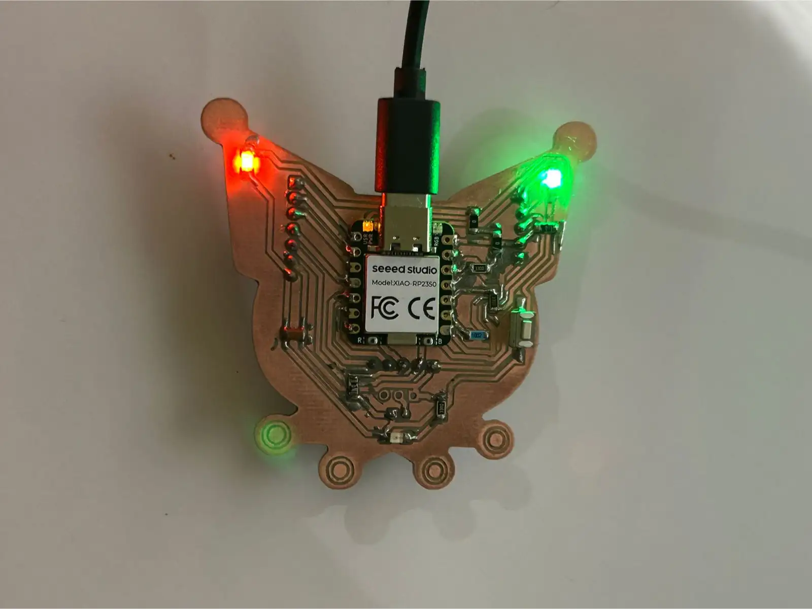 Fig 6. Final Result PCB
To test another method of PCB fabrication, I used a flexible PCB approach. This process involves copper tape and a vinyl cutter. I recommend using a canvas fabric, as it is much more heat resistant during the soldering process compared to plastic based materials, which melt very easily.
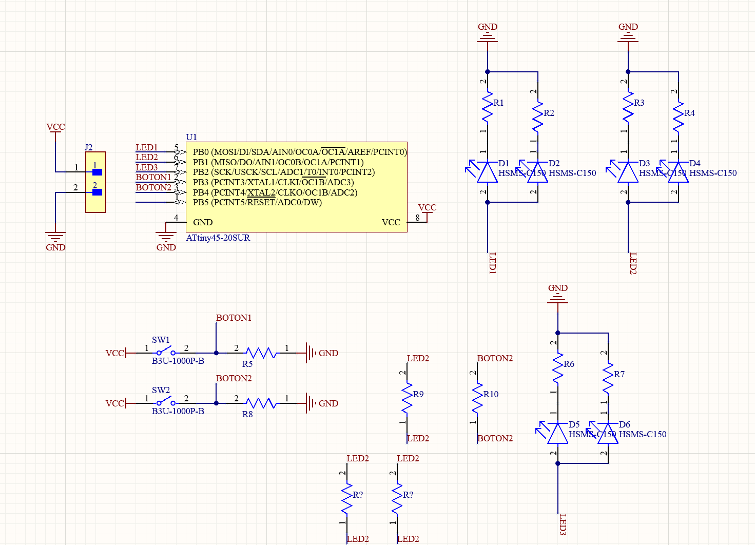 Fig 7. Schematic
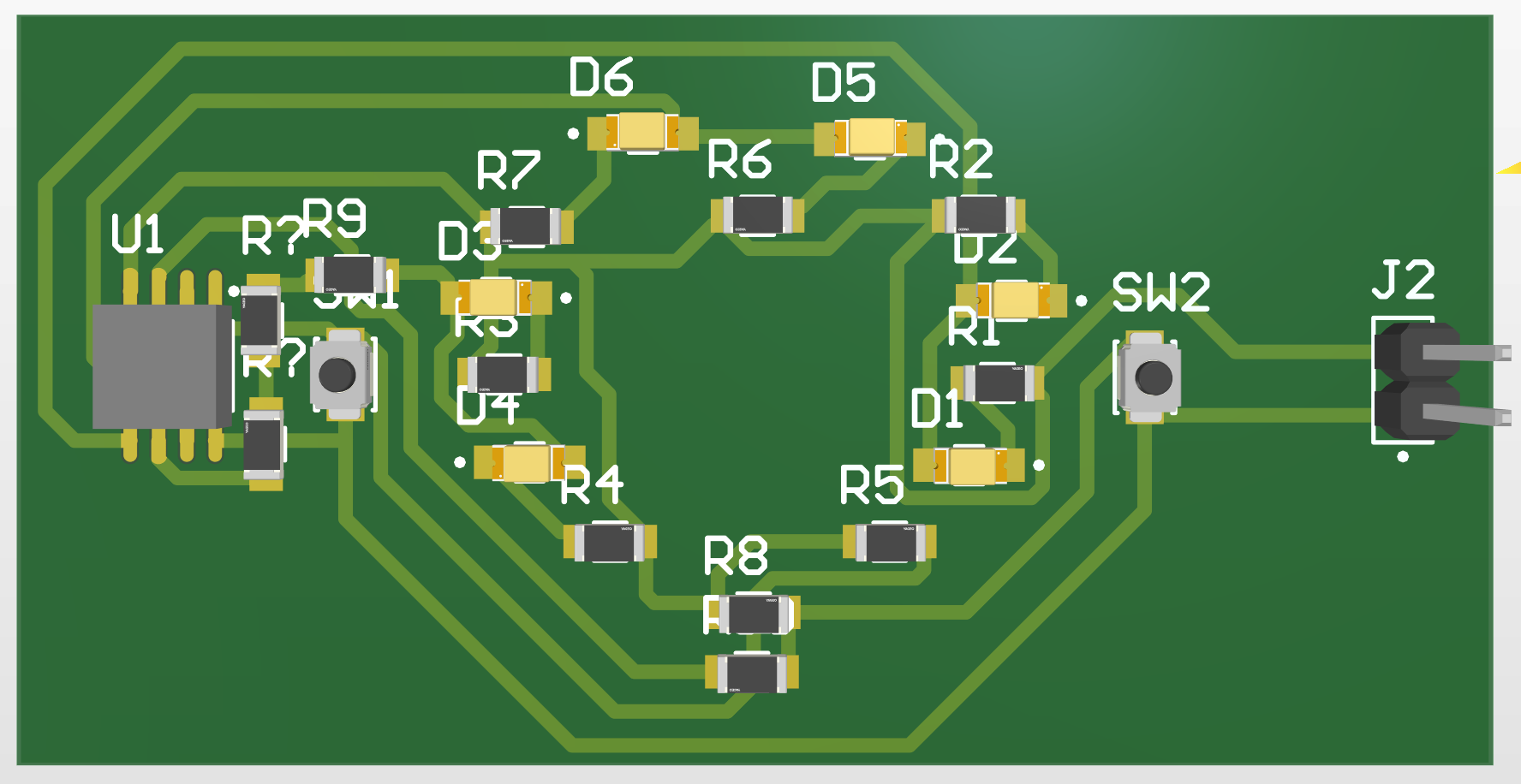 Fig 8. 3D View
I implemented an ATtiny microcontroller with several LEDs and push buttons to allow for flexible programming and testing.
I exported my document as a PDF to later convert it into an SVG using Inkscape. This allowed me to prepare the file for use with the vinyl cutter.
                const int LED1 = 0;
                const int LED2 = 1;
                const int LED3 = 2;
                const int BOTON1 = 3;
                const int BOTON2 = 4;

                int estadoBoton1 = 0;
                int estadoBoton2 = 0;
                int estadoAmbos = 0;

                unsigned long lastDebounceTime1 = 0;
                unsigned long lastDebounceTime2 = 0;
                unsigned long debounceDelay = 50;

                unsigned long lastBlinkTime = 0;
                bool ledState = false;

                const unsigned long blinkInterval = 100;

                void setup() {
                pinMode(LED1, OUTPUT);
                pinMode(LED2, OUTPUT);
                pinMode(LED3, OUTPUT);
                pinMode(BOTON1, INPUT);
                pinMode(BOTON2, INPUT);
                }

                void loop() {
                int lecturaBoton1 = digitalRead(BOTON1);
                int lecturaBoton2 = digitalRead(BOTON2);

                if (lecturaBoton1 == HIGH && lecturaBoton2 == HIGH && (millis() - lastDebounceTime1 > debounceDelay) && (millis() - lastDebounceTime2 > debounceDelay)) {
                    lastDebounceTime1 = millis();
                    lastDebounceTime2 = millis();
                    cambiarEstadoAmbos();
                }
                else if (lecturaBoton1 == HIGH && (millis() - lastDebounceTime1 > debounceDelay)) {
                    lastDebounceTime1 = millis();
                    cambiarEstadoBoton1();
                }
                else if (lecturaBoton2 == HIGH && (millis() - lastDebounceTime2 > debounceDelay)) {
                    lastDebounceTime2 = millis();
                    cambiarEstadoBoton2();
                }

                controlarLEDs();
                }

                void cambiarEstadoBoton1() {
                estadoBoton1++;
                if (estadoBoton1 > 2) {
                    estadoBoton1 = 0;
                }
                }

                void cambiarEstadoBoton2() {
                estadoBoton2++;
                if (estadoBoton2 > 2) {
                    estadoBoton2 = 0;
                }
                }

                void cambiarEstadoAmbos() {
                estadoAmbos++;
                if (estadoAmbos > 2) {
                    estadoAmbos = 0;
                }
                }

                void controlarLEDs() {
                if (estadoAmbos == 2) {
                    unsigned long currentTime = millis();
                    if (currentTime - lastBlinkTime >= blinkInterval) {
                    ledState = !ledState;
                    lastBlinkTime = currentTime;
                    }
                    digitalWrite(LED1, ledState);
                    digitalWrite(LED2, ledState);
                    digitalWrite(LED3, ledState);
                }
                else if (estadoAmbos == 1) {
                    digitalWrite(LED1, HIGH);
                    digitalWrite(LED2, HIGH);
                    digitalWrite(LED3, HIGH);
                }
                else if (estadoBoton1 == 2) {
                    unsigned long currentTime = millis();
                    if (currentTime - lastBlinkTime >= blinkInterval) {
                    ledState = !ledState;
                    lastBlinkTime = currentTime;
                    }
                    digitalWrite(LED1, ledState);
                    digitalWrite(LED2, ledState);
                }
                else if (estadoBoton1 == 1) {
                    digitalWrite(LED1, HIGH);
                    digitalWrite(LED2, HIGH);
                }
                else if (estadoBoton2 == 2) {
                    unsigned long currentTime = millis();
                    if (currentTime - lastBlinkTime >= blinkInterval) {
                    ledState = !ledState;
                    lastBlinkTime = currentTime;
                    }
                    digitalWrite(LED2, ledState);
                    digitalWrite(LED3, ledState);
                }
                else if (estadoBoton2 == 1) {
                    digitalWrite(LED2, HIGH);
                    digitalWrite(LED3, HIGH);
                }
                else {
                    digitalWrite(LED1, LOW);
                    digitalWrite(LED2, LOW);
                    digitalWrite(LED3, LOW);
                }
                }
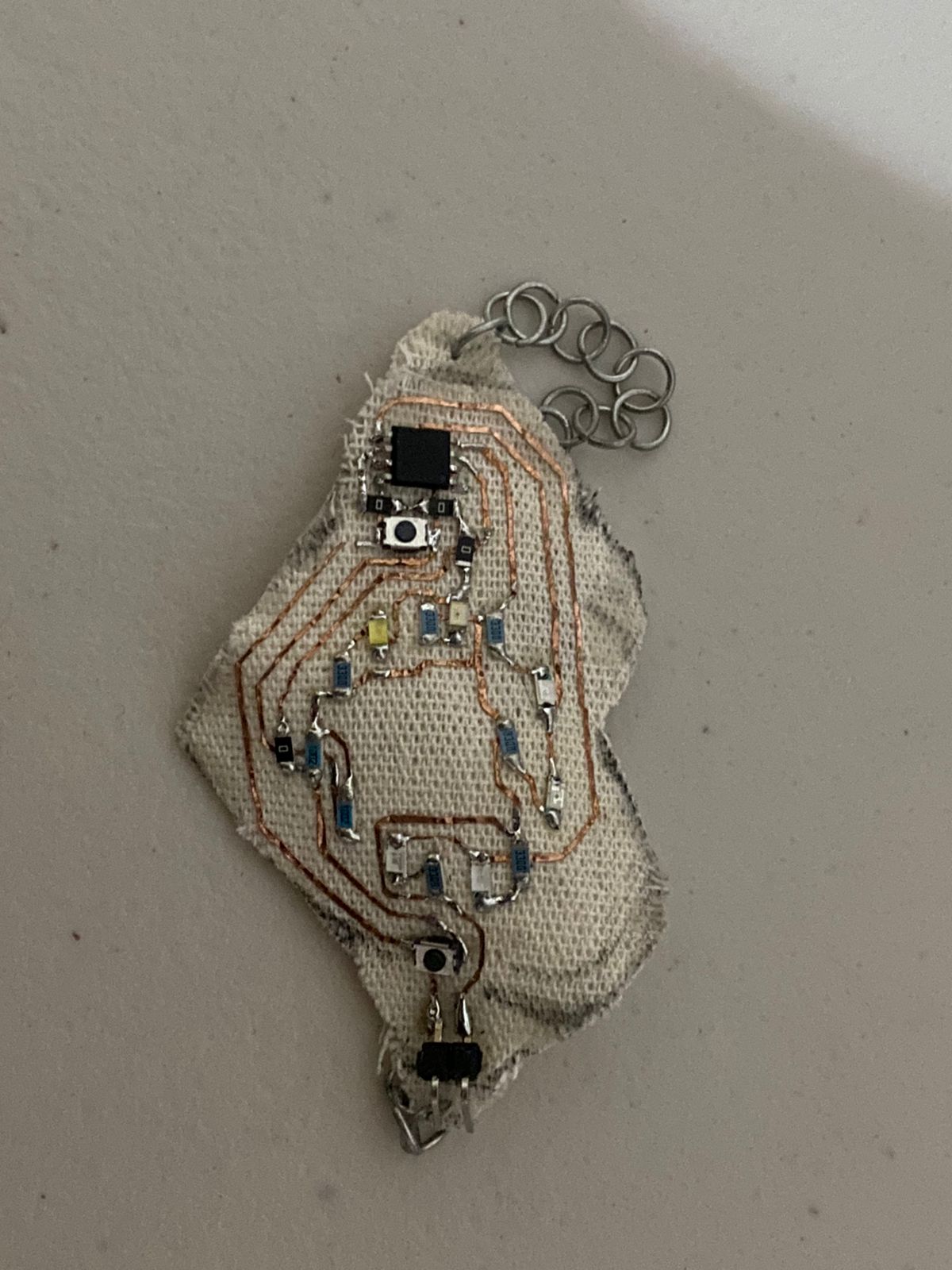 Fig 9. Flexible PCB Bracelet
You can download the files created and used during this week here:
📄 Files.zip