This week's assignment was to design, mill, and assemble a large-format object using a CNC machine. The process began with parametric design in 3D software, considering material tolerances and mechanical joints to ensure a perfect fit without the need for glue or additional screws. Subsequently, toolpaths were generated to proceed with the milling process, concluding with the physical assembly of the piece.
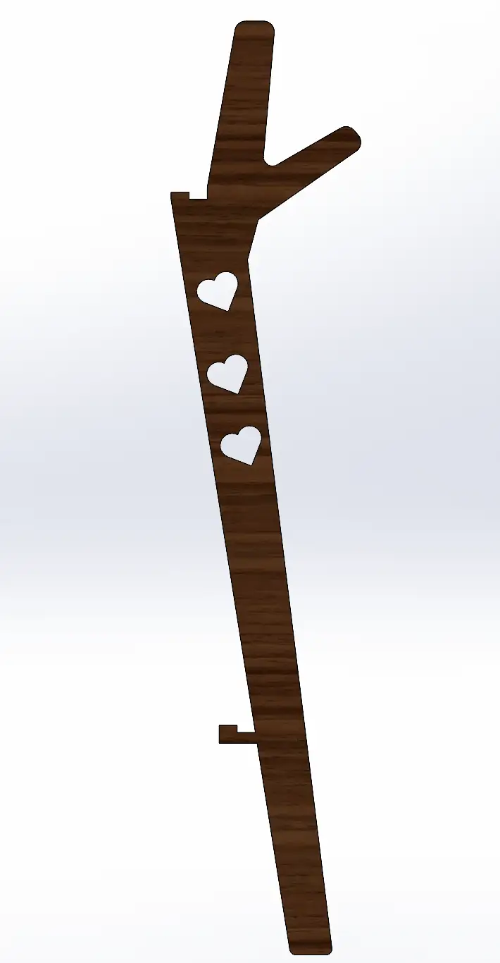
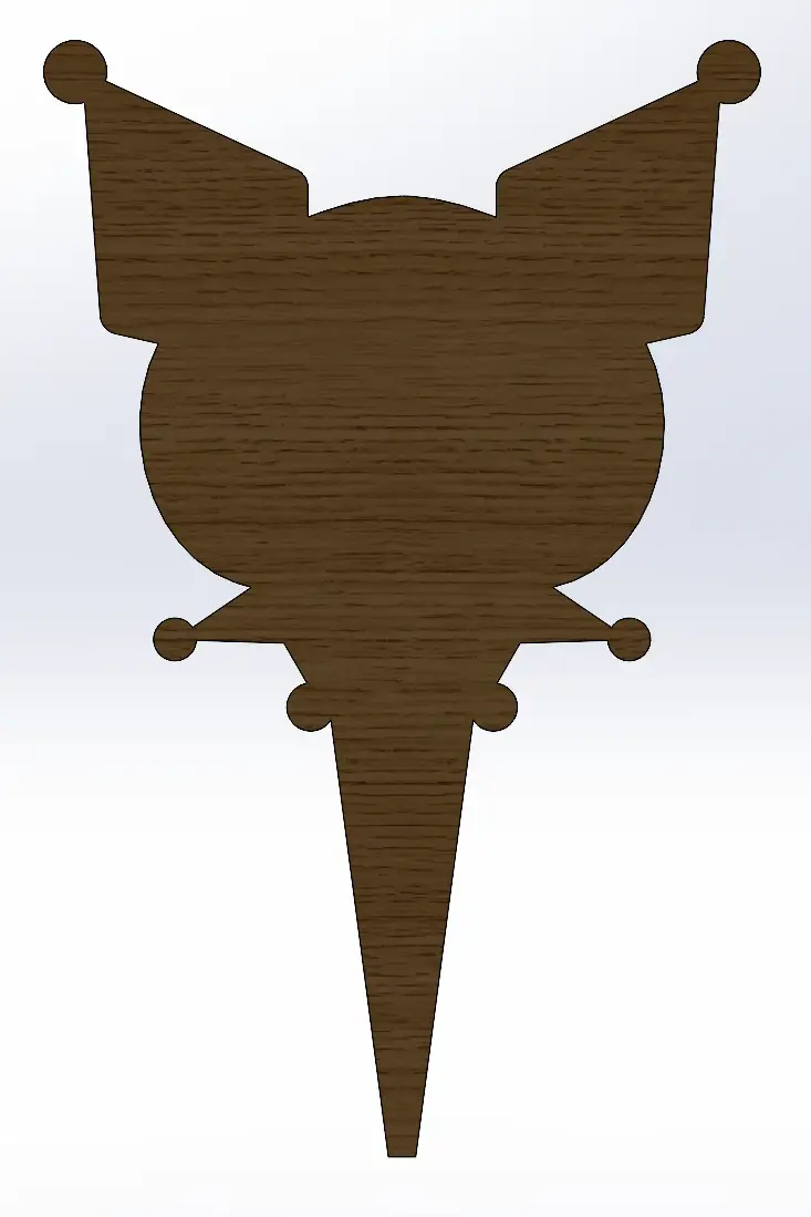
For this week, I decided to build a coat rack inspired by Kuromi to hang my jackets.
Group Assignment
Check here the group assignment for this week for more information about the lab's safety training, test runout, speeds, materials, toolpaths and more about our lab machine.
Design
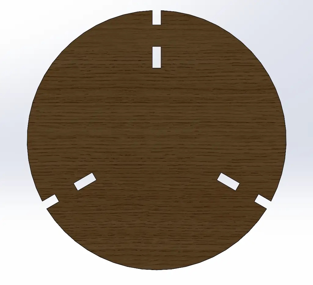
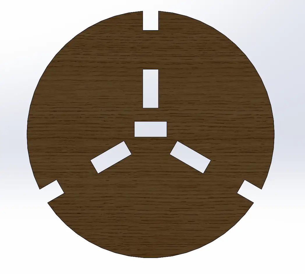
I used SolidWorks to design the pieces, setting the joints to 12 mm to match the thickness of the provided plywood (1.22 m * 2.44 m).
Once I designed all the individual pieces, I put them together in an assembly to verify that everything fit perfectly. This step was essential to ensure the structural integrity of the coat rack before moving to the milling stage. Here is how the final design looks in the assembly:
Fig 1. Assembly
To prepare the files for the next step, I placed all the necessary components into a SolidWorks drawing set to the same dimensions as the plywood sheet (1.22 m x 2.44 m)
It is essential to ensure that all pieces are at a 1:1 scale. Then save the file as a .DXF.
Fig 2. Drawing
⚠️
Note: The distance between pieces must be at least 3 times the tool diameter, this provides sufficient tolerance for the milling process. Additionally, we must leave a considerable margin at the edges of the sheet, as this is where the material will be secured to the CNC bed.
VCarve
To make the document compatible with the CNC machine, we need to generate the toolpaths. For this step, I use VCarve software. Below is a guide on how to use it:
VCarve
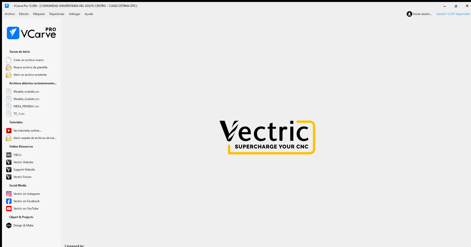
The first step is to create a new document
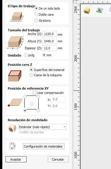
Material Setup configuration
The first thing that appears is the Material Setup configuration. You must define the document size, then set the Z zero, which in this case is on the material surface, and finally set the XY reference point, located at the bottom-left corner.
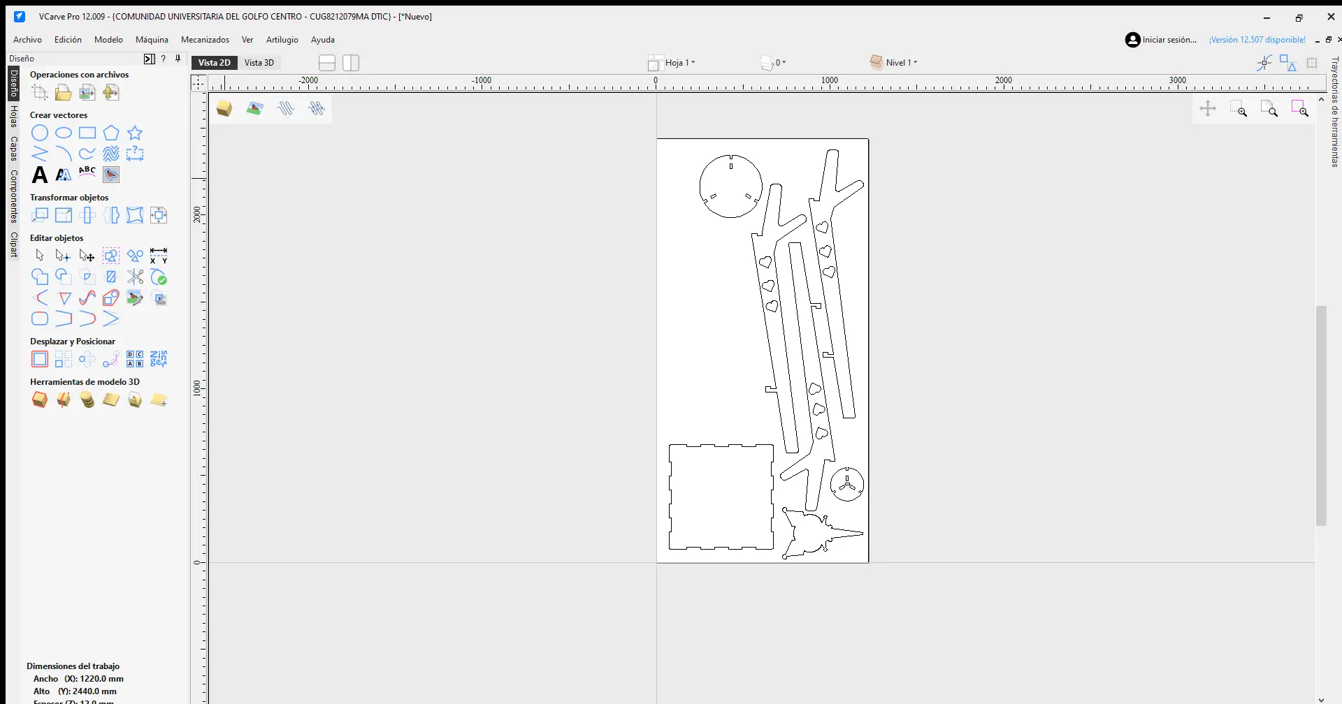
Import Bitmap
To import the DXF file, go to File menu > Import > Import Bitmap, and choose your DXF file.
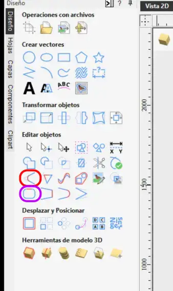
Object menu
In this menu on the left, you will find many options: you can create vectors, edit objects, move and position them, and much more. The most important elements used for this project are circled in red and purple.
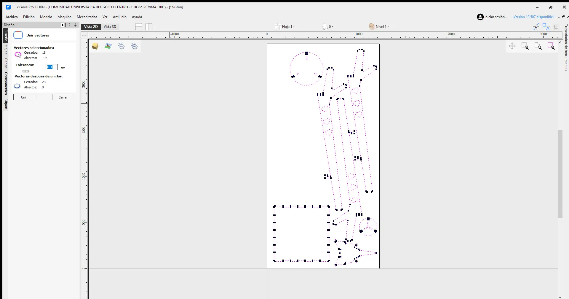
Join vectors
After importing the pieces, the first thing we must do is join the vectors. Since the components are often imported as separate segments, leaving them this way would make the milling process much slower and less efficient. To fix this, we use the Join Vectors option circled in purple.
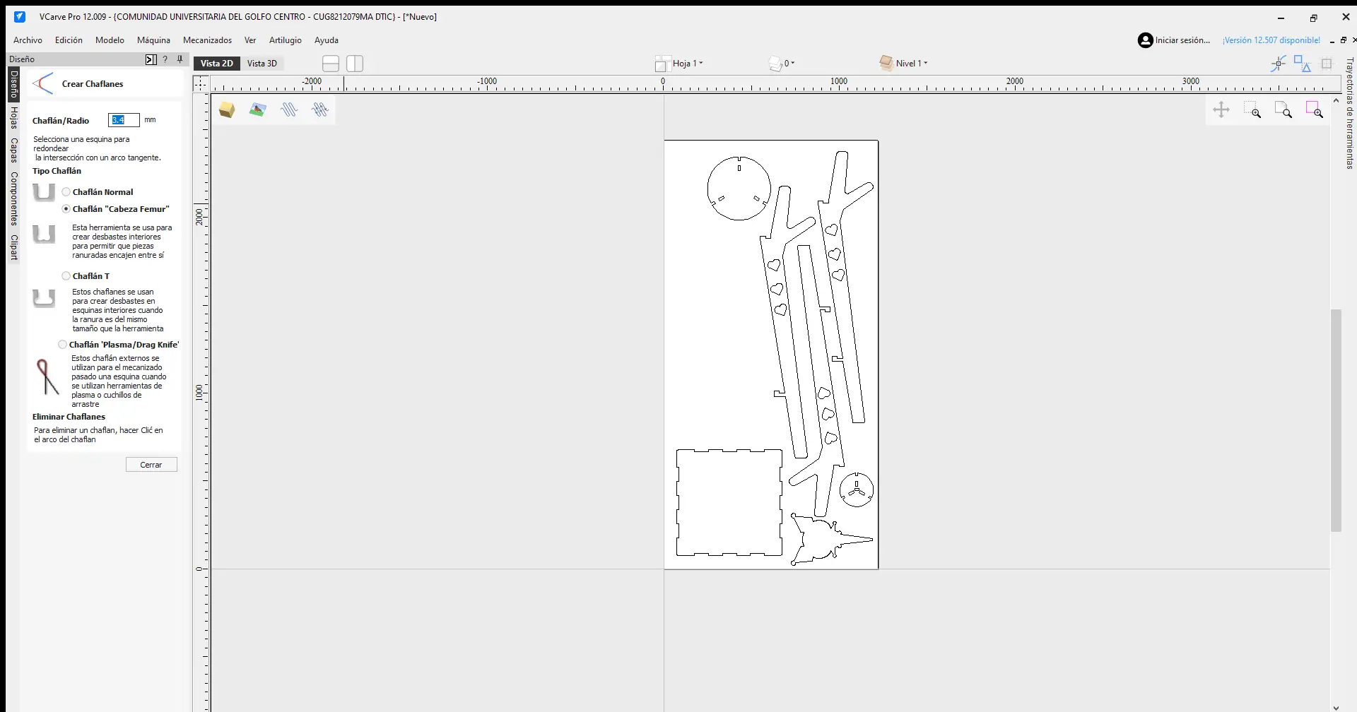
Dog-bone
After joining the vectors, we need to add fillets using the option circled in red. Specifically, we use the femur head style on the interior corners of our joints. The radius must be half the diameter of the tool we are going to use, in this case we were provided with a 1/4 inch tool. This allows the tool to reach further into the corners, ensuring that our joints fit together much better.
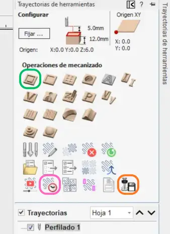
Machining operations
This is the Toolpaths menu, where the machining operations are defined. I used the specific options circled in the image.
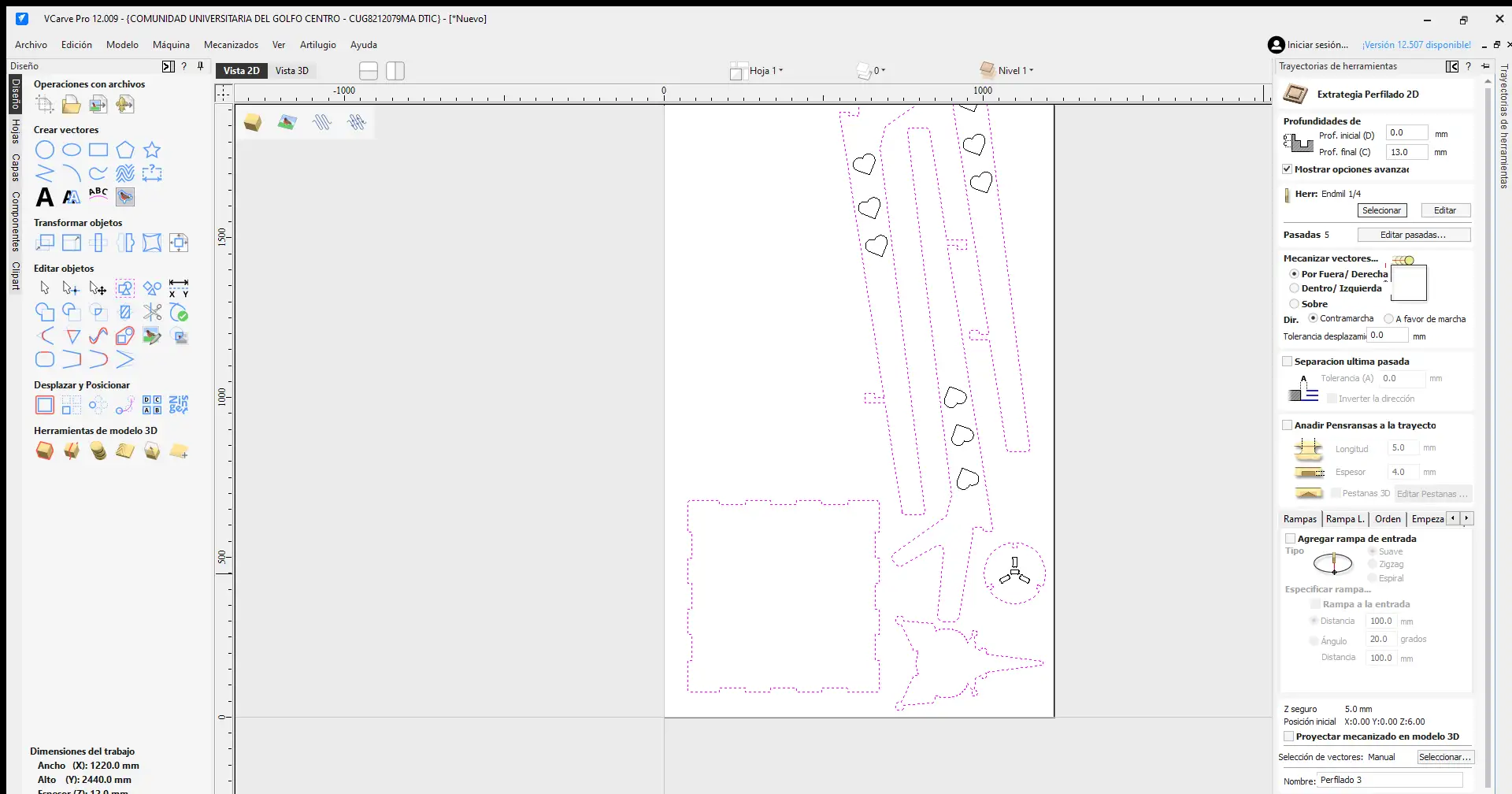
Cut settings
In the green option, we define the tool size, the toolpath, and the stepdown. A critical step is deciding whether the cut will be External or Internal, depending on whether we are milling slots or the outer silhouettes. Additionally, the cutting depth should be 1 mm deeper than the material thickness to ensure the pieces are cut all the way through.
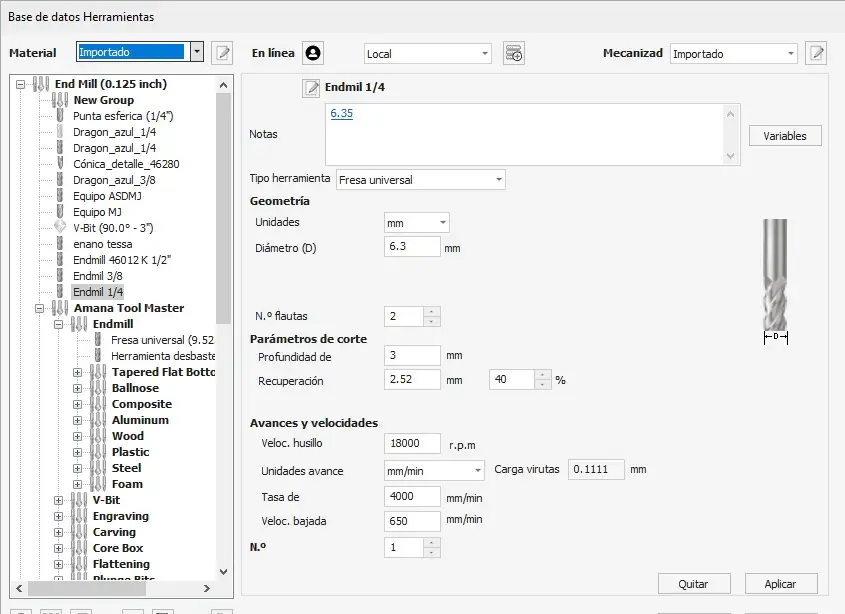
Tool settings
In the tool menu, we select the specific end mill for the job. Here, we define the tool diameter, the number of flutes, the spindle speed in RPM, and the feed rate. To determine the correct parameters, I used a Chipload Calculator, which suggested a speed of 9000 RPM. However, I decided to use 4500 RPM to ensure more control and prevent the pieces from moving during the process.
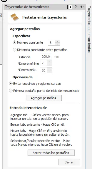
Tabs
To ensure the pieces don't fly off when they are completely cut, we have to add Tabs. In this menu, you can edit the number of tabs you want to add depending on the size of the piece. You can also move them to different positions to avoid placing them in areas where they would be difficult to remove later. Once finished, you close the menu. The recommended size for these tabs is 5 mm * 4 mm.
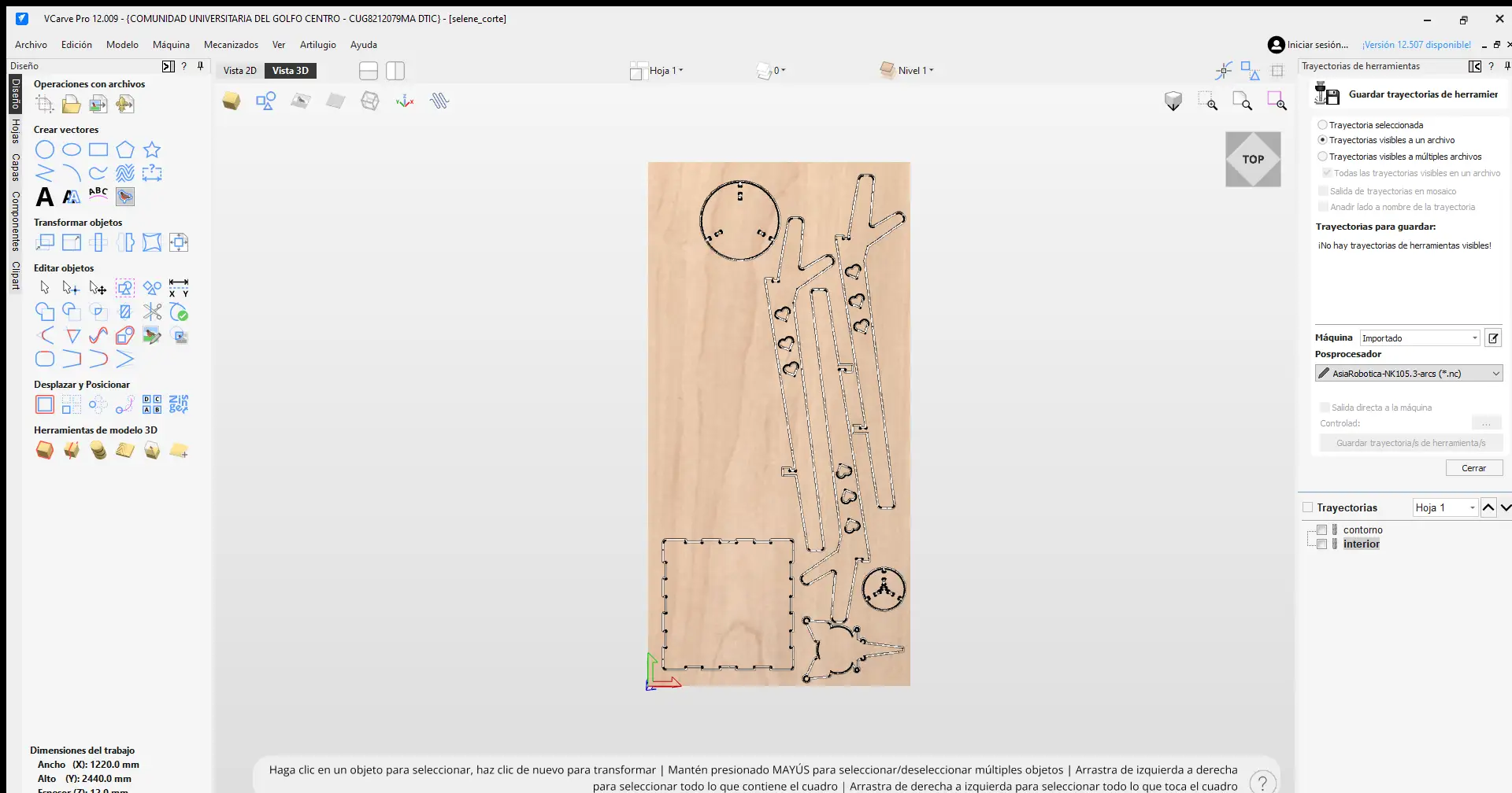
Time and save
To finish, click Calculate to generate the toolpaths. In my case, I generated two paths: the internal cuts and the external profile. In the orange option, we export our document, where we can select the specific machine we are using and save the file to a USB drive for the CNC. Finally, in the pink option allows us to see an estimated time of how long the job will take.
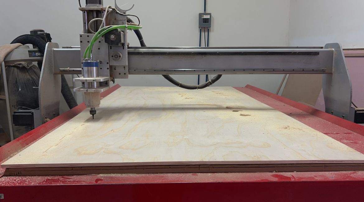
At FabLab Puebla, we have two routers: the Asia Robotica and the Mach 3. For this project, I used the Mach 3.
Mach 3
Motor power: 4 HP at 24000 rpm
Power Supply: 220v/2F/3.5KW
Dimensions: 3 x 1.8 x 1.7 mts
Compatible file: .txt
Before operating the CNC, it is mandatory to wear the proper personal protective equipment, which includes:
Required Personal Protective Equipment
Safety Glasses
Protection against wood chips and high-speed debris during the milling process.
Lab Coat
Shields your clothing from dust and prevents loose fabric from catching in the spindle.
Security Boots
Steel-toe protection is mandatory for handling heavy and sharp objects.
Earplugs
Protect your ears from the high noise levels generated by the CNC router.
It is also important to avoid wearing any type of jewelry on your hands or wrists. Additionally, for those with long hair, it must be kept tied back to prevent it from getting caught in the router.
Now here is a short tutorial on how to operate the Mach 3:
Mach 3
Once your document is ready, you must save it in .txt format, which is compatible with this CNC.
It is also important to secure your material to the CNC bed using nails along the edges to prevent it from moving. Try to ensure it is not warped so that the tool doesn't accidentally remove material where you don't want it to.
Machine´s axes
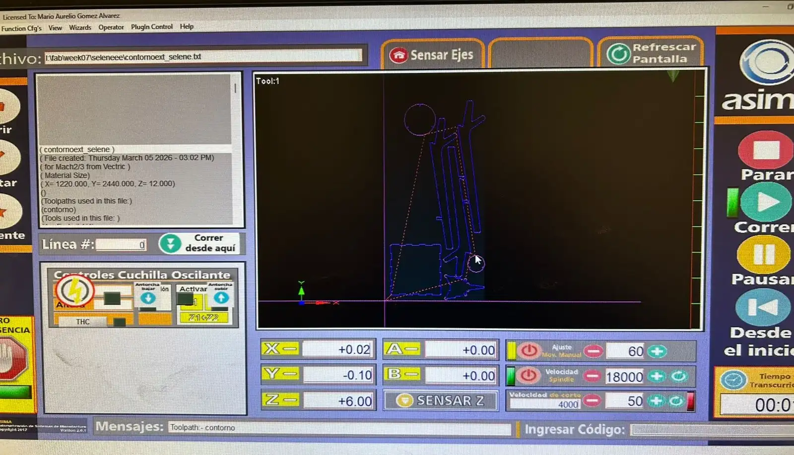
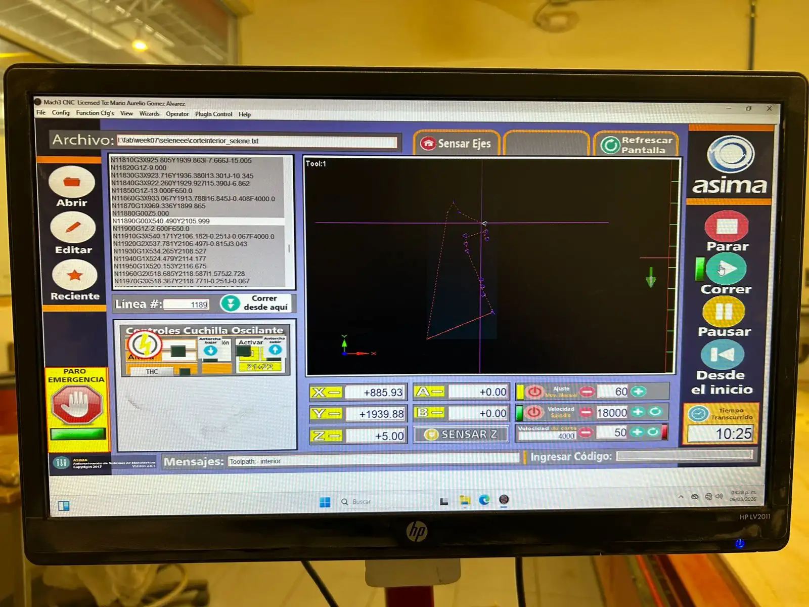
To operate this CNC, there is a computer where you must insert your USB drive to extract your document.
The XY axes are moved using the keyboard arrow keys; to move the Z axis, use Pg Up and Pg Down keys. To make the movement of the axes faster, hold down the Shift key.
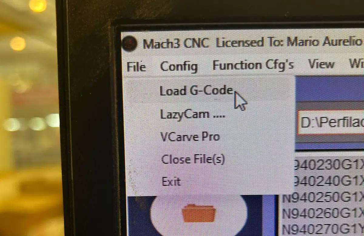
Import G-code
To import the G-code, go to File and then Load G-Code. The code will appear in the text box of the interface.
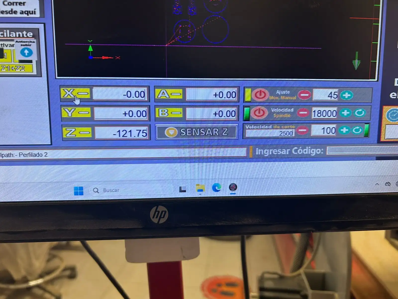
Set point
To define the setpoints, once the spindle head is in the indicated position, press the yellow button for each axis to define the zero point.
Percentage
To control the manual jog speed and the cutting feed rate, you can edit the percentages in this section.
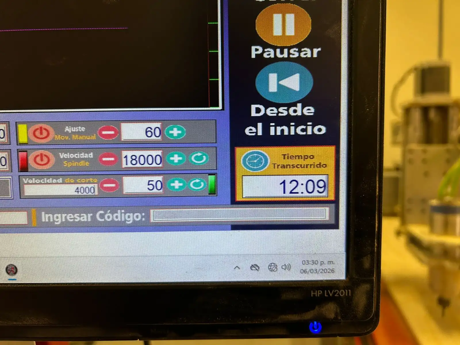
Start
To start, simply press the green play button. With the other buttons on the right menu, you can pause or completely stop the process for any reason. There is also the emergency stop button.
It is important to always keep an eye on the CNC and never leave it unsupervised, as an accident could occur. Also, use the vacuum to keep the work area clean.
 Fig 1. Assembly
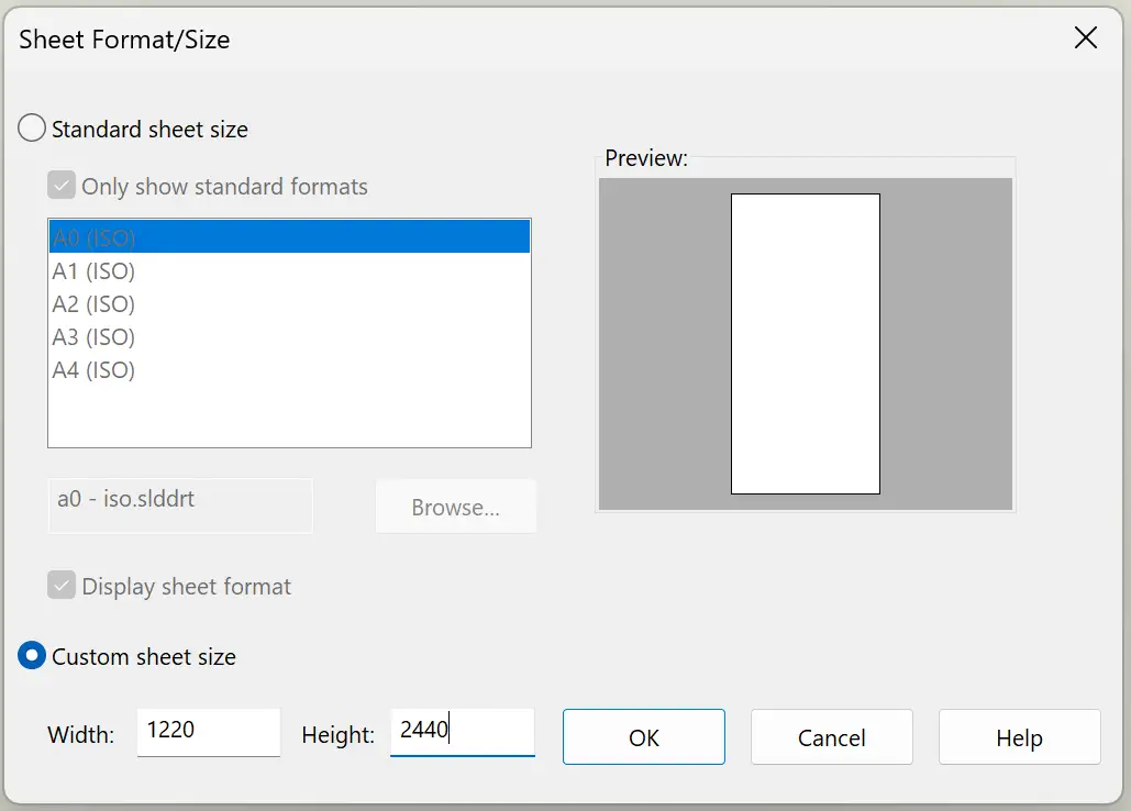
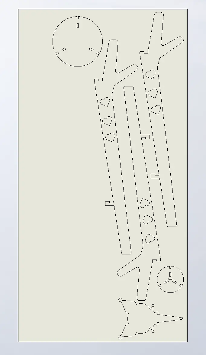 Fig 2. Drawing
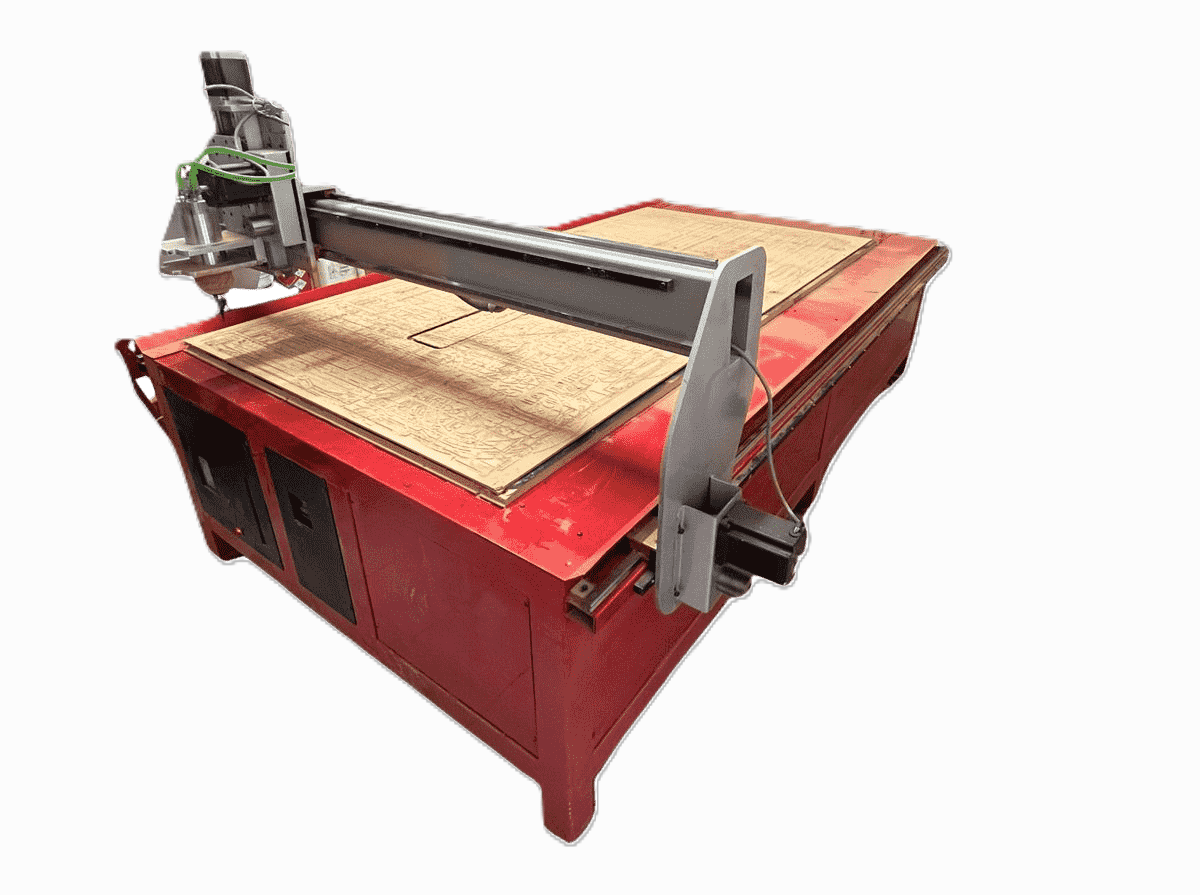


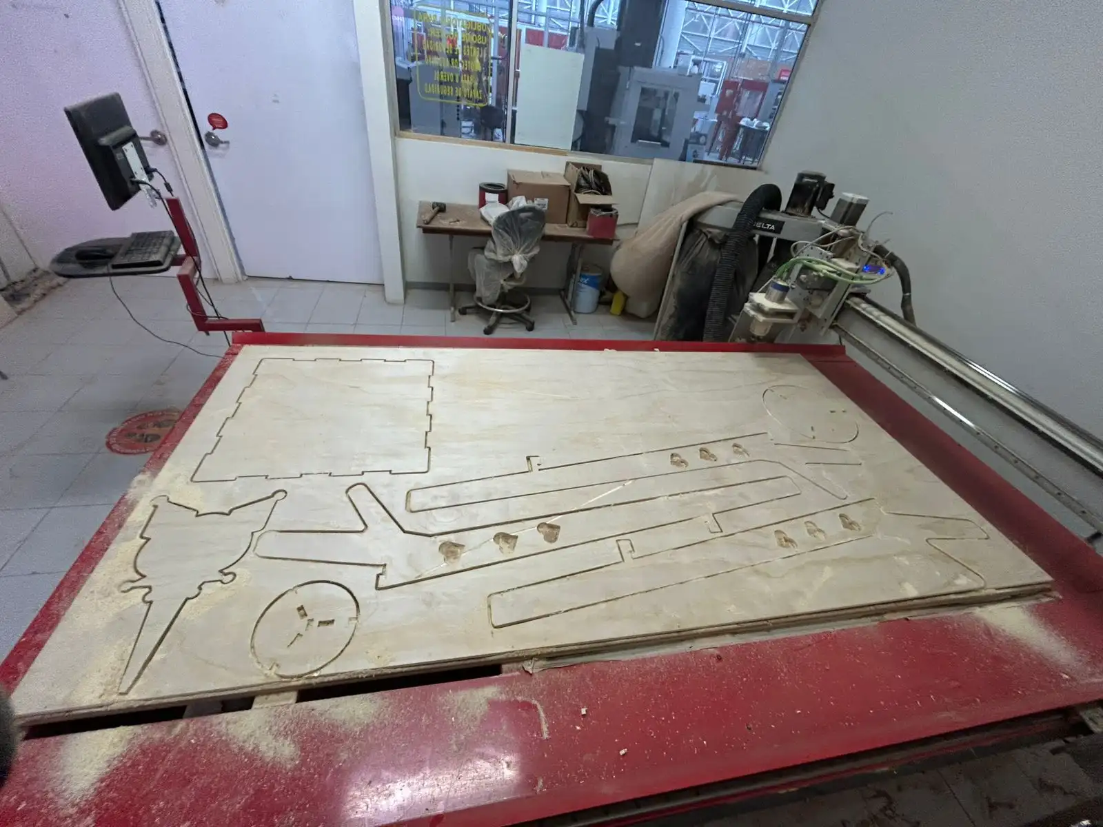 Fig 3. Cutting result
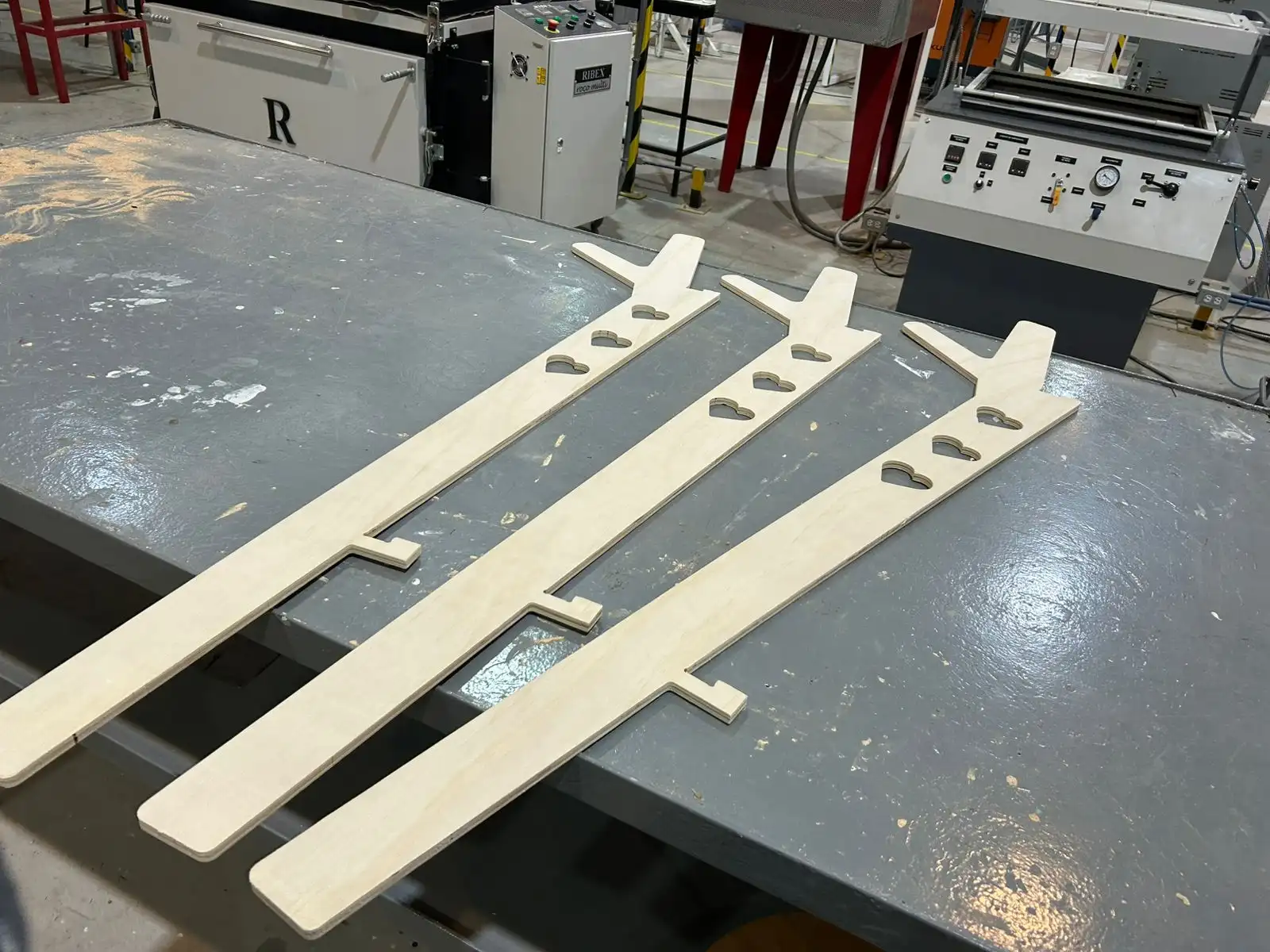 Fig 4. Sanding result
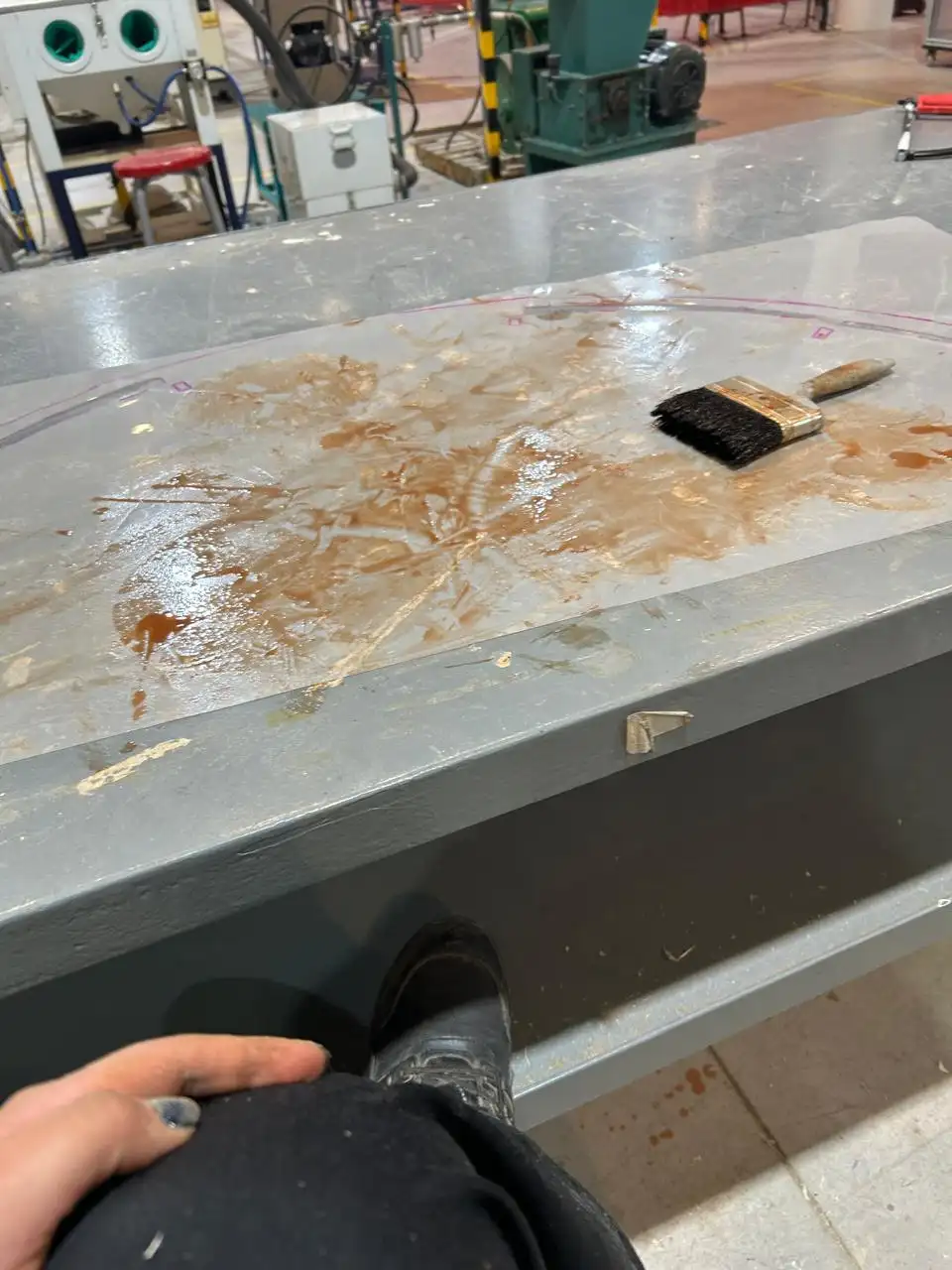
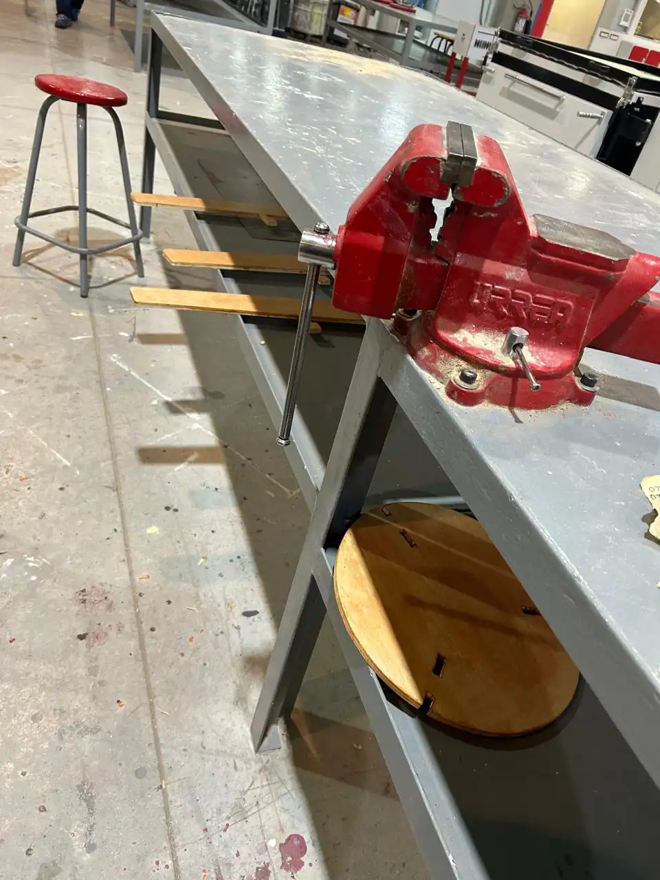
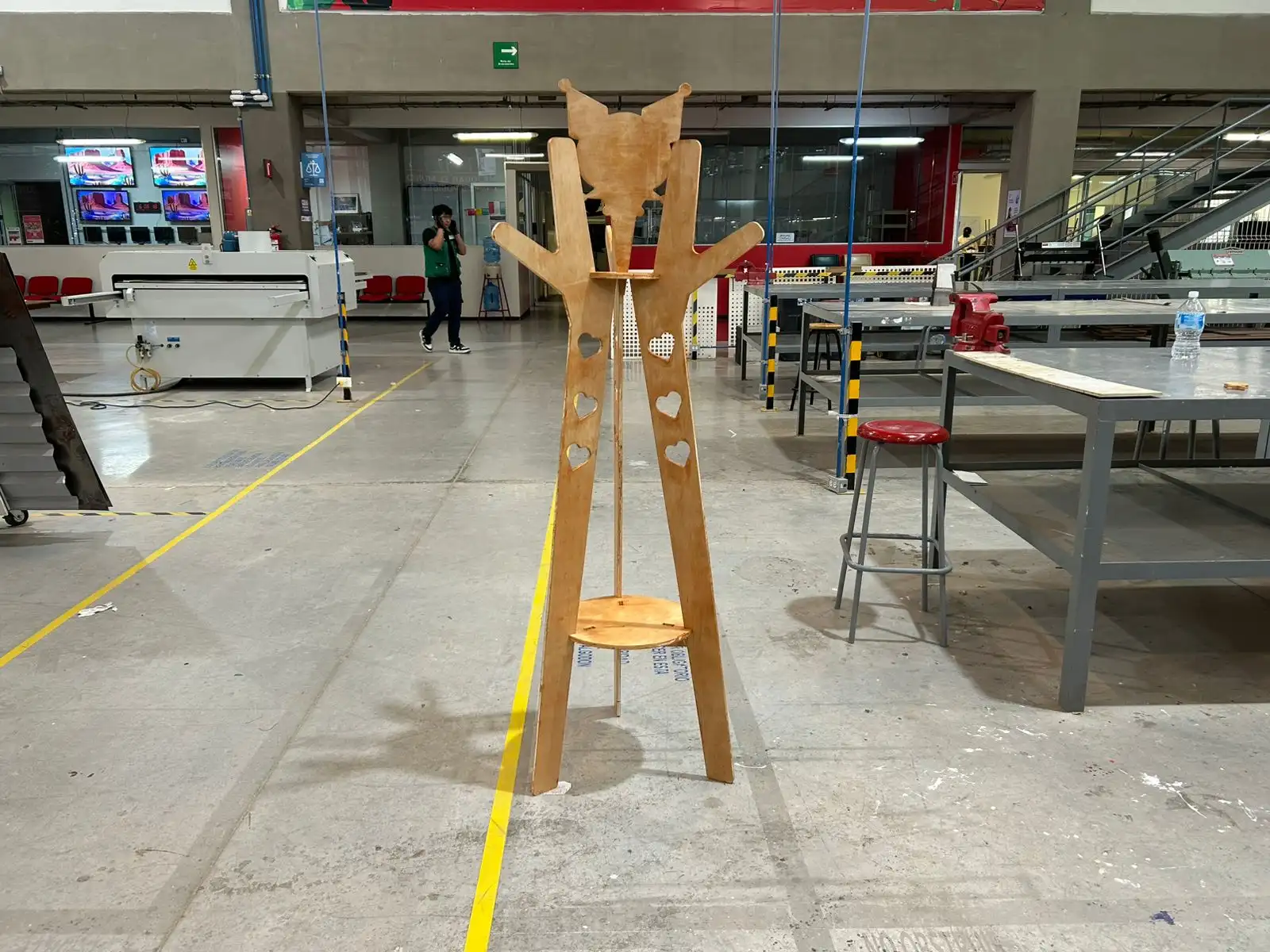 Fig 5. Final result
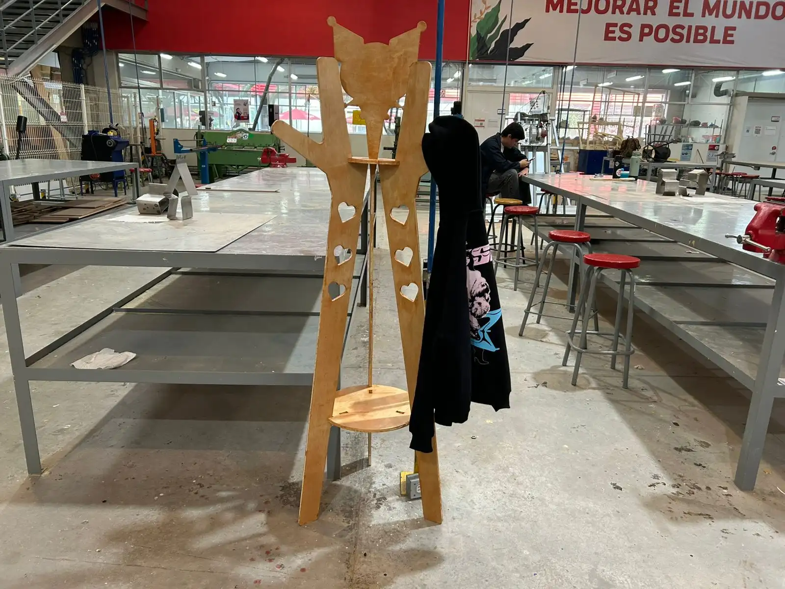 Fig 6. Final result