Zen Garden Slice
ZEN GARDEN - PROJECT PRESENTATION SLIDE
GROUP PROJECT

CNC SAND PLOTTER

Fab Lab Puebla 2026 — Designing a magnet-driven XY plotter.

Javier Vega
Derek Rodríguez
Oscar Guzmán Jorge
Greayshell Cielo Gómez
Itzel Eunice Rodríguez Moreno

MISSION BRIEFING

This documentation covers the collective effort to build a CNC machine. We decided to build an 18x18 cm Sand Plotter. This machine uses a permanent neodymium magnet mounted on a 2-axis (X/Y) gantry hidden underneath a table. The magnet drags a steel ball bearing through a layer of fine sand, tracing continuous geometric patterns and images.

01. MECHANICAL DESIGN

The physical structure is based on a 2-axis Cartesian gantry system. It uses stepper motors to drive timing belts, allowing precise movement across the 18x18 cm work area. The frame is constructed from laser-cut panels to ensure structural rigidity, combined with custom 3D-printed brackets and motor mounts to hold the linear rods and bearings securely in place.

Mechanical Assembly 1
The machine model in SolidWorks
Mechanical Assembly 2
The machine in real life

02. ELECTRONICS & WIRING

The brain of the machine is a custom-milled PCB housing an ESP32-C6 microcontroller. This mainboard distributes power to the stepper motor drivers (acting as the CNC shield) and handles the signal routing for both the X and Y axes, ensuring reliable logic pulses and a clean wire management system under the plotter bed.

Electronics 1
The ESP32-C6 Mainboard
Electronics 2
The mainboard come to life

03. SOFTWARE & UI

The machine operates completely wirelessly. A custom client-side web application runs on the user's laptop, processing images and generating continuous G-code toolpaths using a nearest-neighbor algorithm. This G-code is then sent Over-The-Air (OTA) to the ESP32-C6's internal HTTP server. Custom firmware on the ESP32 parses these commands and executes the precise stepping sequences.

Software UI
Wireless Mission Control Interface
G-Code Path
Continuous toolpath generation preview

TEAM INDIVIDUAL LOGS

Click each member's name to see their specific contributions to the machine.

CAD & Simulation

Derek Rodríguez

Personal page right here:

Derek was responsible for the complete 3D design in SolidWorks. He modeled every component and ran motion simulations to validate the kinematics before any part was fabricated.

  • Full machine modeled in SolidWorks — frame, gantry, motor mounts and belt routing
  • Ran motion simulation to verify XY travel and clearances before fabrication
  • Defined tolerances and exported technical drawings used by the fabrication team
Assembly view
Gantry Assembly View
Final parts
Final Parts Overview
Firmware & Motor Control

Oscar Guzmán Jorge

Personal page right here:

Oscar wrote the firmware running on the ESP32-C6. He implemented a G-code parser and the stepper motor control routines that translate coordinate commands into precise physical movement on both axes.

  • Programmed the ESP32-C6 to receive and parse G-code commands
  • Implemented stepper motor movement routines for both X and Y axes
  • Handled step timing and direction logic for smooth, accurate motion
  • Exposed a WiFi endpoint to receive G-code instructions from the web UI
[The Machine is Moving]
// Motor Control — ESP32-C6 Firmware
//#include <math.h>
#include <stdio.h>
#include <stdlib.h>
#include <string.h> 
#include "freertos/FreeRTOS.h"
#include "freertos/task.h"
#include "driver/gpio.h"
#include "driver/gptimer.h"

#include "nvs_flash.h"
#include "esp_netif.h"
#include "esp_event.h"
#include "esp_wifi.h"
#include "esp_http_server.h"

// --- WIFI CREDENTIALS ---
#define WIFI_SSID "POCO X7 Pro"
#define WIFI_PASS "oscar9546"


#define PIN_STEP_X    0
#define PIN_STEP_Y    1
#define PIN_DIR_X     2
#define PIN_DIR_Y     21
#define PIN_ENABLE    22
#define PIN_LIM_X     23
#define PIN_LIM_Y     16

// VOLATILE VARIABLES (Interrupt)
volatile int32_t current_x = 0, current_y = 0;
volatile int32_t target_x = 0,  target_y = 0;
volatile int32_t dx, dy, sx, sy, err;
volatile bool is_moving = false;
volatile bool pulse_high = false;

//G-CODE CALIBRATION & MEMORY
#define STEPS_PER_MM 183.33f 
float current_x_mm = 0.0;
float current_y_mm = 0.0;


// 50KB capacity
char mission_buffer[50000]; 
volatile bool mission_ready = false;


static bool IRAM_ATTR stepper_timer_cb(gptimer_handle_t timer, const gptimer_alarm_event_data_t *edata, void *user_ctx) {
    if (!is_moving) return false;

    if (pulse_high) {
        
        gpio_set_level(PIN_STEP_X, 0);
        gpio_set_level(PIN_STEP_Y, 0);
        pulse_high = false;

        
        if (current_x == target_x && current_y == target_y) {
            is_moving = false;
        }
    } else {
        //Bresenham's line algorithm calculation
        if (current_x != target_x || current_y != target_y) {
            int32_t e2 = 2 * err;
            bool step_x = false;
            bool step_y = false;

            if (e2 >= dy) {
                err += dy;
                current_x += sx;
                step_x = true;
            }
            if (e2 <= dx) {
                err += dx;
                current_y += sy;
                step_y = true;
            }

            if (step_x) gpio_set_level(PIN_STEP_X, 1);
            if (step_y) gpio_set_level(PIN_STEP_Y, 1);
            pulse_high = true;
        }
    }
    return false; 
}


void move_to(int32_t x, int32_t y) {
    // Redundancy check, gnore command if already at target
    if (x == current_x && y == current_y) {
        return; 
    }

    // Wait for the previous movement to complete
    while(is_moving) { 
        vTaskDelay(pdMS_TO_TICKS(10)); 
    }

    target_x = x;
    target_y = y;

    // Bresenham variables setup
    dx = abs(target_x - current_x);
    sx = current_x < target_x ? 1 : -1;
    dy = -abs(target_y - current_y);
    sy = current_y < target_y ? 1 : -1;
    err = dx + dy;

    // Set physical direction on drivers
    gpio_set_level(PIN_DIR_X, sx > 0 ? 1 : 0);
    gpio_set_level(PIN_DIR_Y, sy > 0 ? 1 : 0);

    is_moving = true;
}


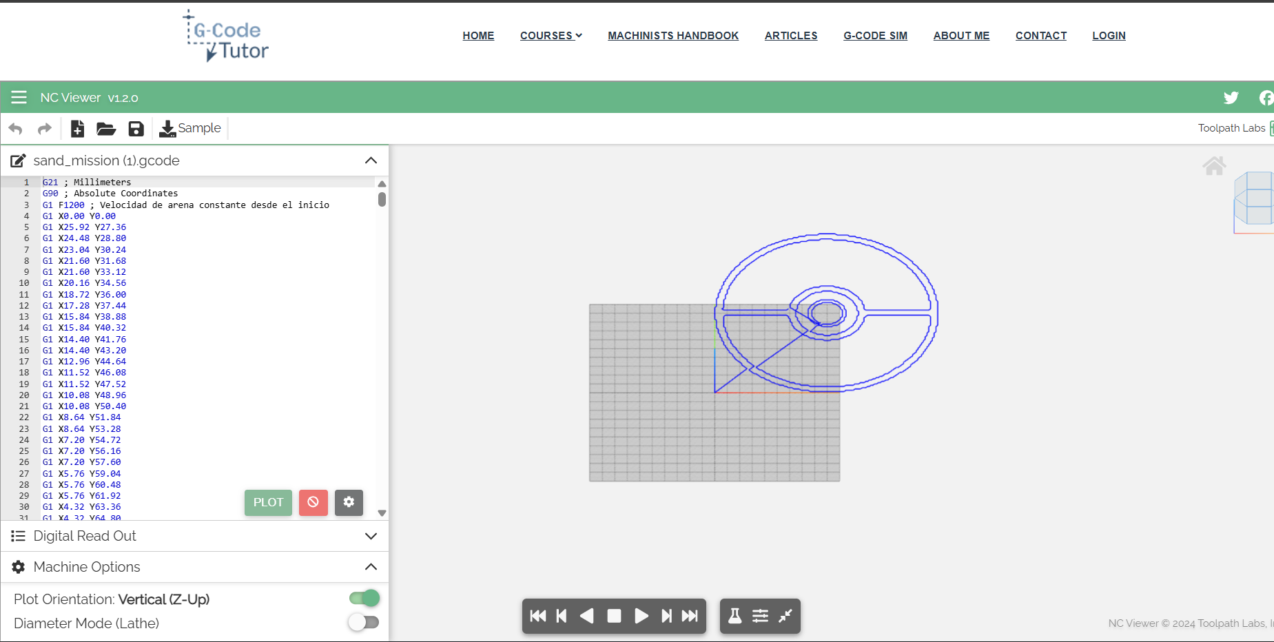
void execute_gcode(const char* gcode_line) {
    float target_x_mm = current_x_mm;
    float target_y_mm = current_y_mm;

    // Parse X coordinate
    char *x_ptr = strchr(gcode_line, 'X');
    if (x_ptr != NULL) { target_x_mm = atof(x_ptr + 1); }

    // Parse Y coordinate
    char *y_ptr = strchr(gcode_line, 'Y');
    if (y_ptr != NULL) { target_y_mm = atof(y_ptr + 1); }

    // Update memory
    current_x_mm = target_x_mm;
    current_y_mm = target_y_mm;

    // Convert millimeters to steps
    int32_t steps_x = (int32_t)(target_x_mm * STEPS_PER_MM);
    int32_t steps_y = (int32_t)(target_y_mm * STEPS_PER_MM);

    move_to(steps_x, steps_y);
}

// initialization
void init_stepper_gpios() {
    gpio_config_t io_conf = {0};
    io_conf.intr_type = GPIO_INTR_DISABLE;
    io_conf.mode = GPIO_MODE_OUTPUT;
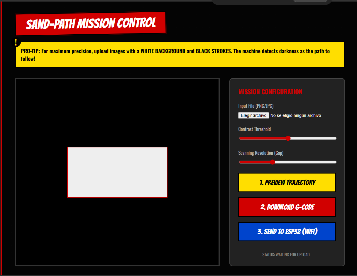
    io_conf.pin_bit_mask = (1ULL< CONNECTED. IP FOR WEBPAGE: " IPSTR "/upload\n\n", IP2STR(&event->ip_info.ip));
    }
}

esp_err_t upload_handler(httpd_req_t *req) {
    
    httpd_resp_set_hdr(req, "Access-Control-Allow-Origin", "*");
    
    if (req->method == HTTP_OPTIONS) {
        httpd_resp_set_hdr(req, "Access-Control-Allow-Methods", "POST, OPTIONS");
        httpd_resp_set_hdr(req, "Access-Control-Allow-Headers", "Content-Type");
        httpd_resp_send(req, NULL, 0);
        return ESP_OK;
    }

    int total_len = req->content_len;
    
    // RAM Protection: Reject files larger than the buffer
    if (total_len >= sizeof(mission_buffer)) {
        httpd_resp_send_500(req);
        return ESP_FAIL;
    }

    int received = 0;
    while (received < total_len) {
        int ret = httpd_req_recv(req, mission_buffer + received, total_len - received);
        if (ret <= 0) return ESP_FAIL;
        received += ret;
    }
    mission_buffer[total_len] = '\0'; 

    printf("G-Code received: %d bytes\n", total_len);
    httpd_resp_sendstr(req, "Received on the ESP32 successfully");
    
    // Trigger the main loop
    mission_ready = true; 
    return ESP_OK;
}

void start_webserver() {
    httpd_config_t config = HTTPD_DEFAULT_CONFIG();
    httpd_handle_t server = NULL;
    if (httpd_start(&server, &config) == ESP_OK) {
        httpd_uri_t uri_post = { .uri = "/upload", .method = HTTP_POST, .handler = upload_handler };
        httpd_register_uri_handler(server, &uri_post);
        httpd_uri_t uri_opts = { .uri = "/upload", .method = HTTP_OPTIONS, .handler = upload_handler };
        httpd_register_uri_handler(server, &uri_opts);
    }
}


void app_main(void) {
    printf("Initializing CNC system with WiFi...\n");
    init_stepper_gpios();
    init_limits(); 

    // Setup GPTimer for step generation
    gptimer_handle_t gptimer = NULL;
    gptimer_config_t timer_config = {
        .clk_src = GPTIMER_CLK_SRC_DEFAULT,
        .direction = GPTIMER_COUNT_UP,
        .resolution_hz = 1000000, 
    };
    gptimer_new_timer(&timer_config, &gptimer);
    gptimer_event_callbacks_t cbs = { .on_alarm = stepper_timer_cb };
    gptimer_register_event_callbacks(gptimer, &cbs, NULL);
    gptimer_alarm_config_t alarm_config = {
        .alarm_count = 350, // Microseconds per step (Speed controller)
        .reload_count = 0,
        .flags.auto_reload_on_alarm = true,
    };
    gptimer_set_alarm_action(gptimer, &alarm_config);
    gptimer_enable(gptimer);
    gptimer_start(gptimer);

    // Initialize WiFi Subsystem
    nvs_flash_init();
    esp_netif_init();
    esp_event_loop_create_default();
    esp_netif_create_default_wifi_sta();
    wifi_init_config_t cfg = WIFI_INIT_CONFIG_DEFAULT();
    esp_wifi_init(&cfg);
    esp_event_handler_instance_register(WIFI_EVENT, ESP_EVENT_ANY_ID, &wifi_event_handler, NULL, NULL);
    esp_event_handler_instance_register(IP_EVENT, IP_EVENT_STA_GOT_IP, &wifi_event_handler, NULL, NULL);
    
    wifi_config_t wifi_config = { .sta = { .ssid = WIFI_SSID, .password = WIFI_PASS } };
    esp_wifi_set_mode(WIFI_MODE_STA);
    esp_wifi_set_config(WIFI_IF_STA, &wifi_config);
    esp_wifi_start();

    // Start HTTP Server
    start_webserver();

    while(1) {
        if (mission_ready) {
            printf("Executing G-Code Mission...\n");
            
            // WAKE UP MOTORS
            gpio_set_level(PIN_ENABLE, 0); 
            vTaskDelay(pdMS_TO_TICKS(100)); // Allow coils to magnetize
            
            char *saveptr;
            char *line = strtok_r(mission_buffer, "\r\n", &saveptr);
            
            // Process file line by line
            while (line != NULL) {
                if (strlen(line) > 2) {
                    execute_gcode(line);
                }
                line = strtok_r(NULL, "\r\n", &saveptr);
                vTaskDelay(pdMS_TO_TICKS(2)); 
            }
            
            printf("Routing completed. Cooling down motors...\n");
            
            
            gpio_set_level(PIN_ENABLE, 1); 
            
            mission_ready = false;
        }
        
        vTaskDelay(pdMS_TO_TICKS(100)); 
    }
}


          Web Interface & Wireless G-code          

Javier Vega

          Personal page right here:          

            Javier built a custom web interface hosted on the ESP32. It allows uploading an image from any laptop, previewing the G-code toolpath, and sending it wirelessly to the machine — no USB cable required.          


  • Built a browser-based UI to upload images and preview the toolpath
  •            
  • Implemented image-to-G-code conversion running client-side in the browser
  •            
  • Configured the ESP32-C6 as a WiFi AP + WebServer to receive G-code wirelessly
  •            
  • Enabled fully cable-free operation between laptop and machine controller
  •          
         
           
              Sand Mesh Mission Control web UI              
Sand Mesh Mission Control — Web Interface
           
           
              G-code simulation preview              
G-code Toolpath Simulation (browser preview)


//Getting the IP — ESP32-C6 IP adress
         
#include <WiFi.h>
#include <WebServer.h>

const char* ssid ="WIFI NAME";
const char* password ="PASSWORD";

WebServer server(80);

void setup() {
  Serial.begin(115200);
  delay(1000);
  
  WiFi.begin(ssid, password);
  Serial.print("Conectando al Wi-Fi");
  //THE LAPTOP AND THE ESP32 MUST BE ON THE SAME WIFI NETWORK FOR THIS TO WORK
  while (WiFi.status() != WL_CONNECTED) { 
    delay(500); 
    Serial.print("."); 
  }

  Serial.println("\n¡Conexion exitosa!");
  Serial.print("=== TU IP DE HOY ES: ");
  Serial.print(WiFi.localIP());
  Serial.println(" ===");


  server.on("/upload", HTTP_OPTIONS, []() {
    server.sendHeader("Access-Control-Allow-Origin", "*");
    server.sendHeader("Access-Control-Max-Age", "10000");
    server.sendHeader("Access-Control-Allow-Methods", "POST,GET,OPTIONS");
    server.sendHeader("Access-Control-Allow-Headers", "*");
    server.send(204);
  });

  // GCODE
  server.on("/upload", HTTP_POST, []() {
    // Forzamos el permiso CORS en la respuesta
    server.sendHeader("Access-Control-Allow-Origin", "*");
    
    if (server.hasArg("plain")) {
      String gcodeRecibido = server.arg("plain");
      Serial.println("\n=== NUEVA MISION RECIBIDA ===");
      Serial.println(gcodeRecibido); 
      Serial.println("=============================");
      
      server.send(200, "text/plain", "¡Mision Recibida por la ESP32 de Javi!");
    } else {
      server.send(400, "text/plain", "Error: El payload llego vacio");
    }
  });

  server.enableCORS(true);
  server.begin();
}

void loop() {
  server.handleClient();
}


          Mechanical Assembly          

Itzel Eunice Rodríguez Moreno

          Personal page right here:          

            Itzel was the hands-on builder of the team. She took Derek's SolidWorks files from digital to physical — cutting, printing, and assembling every mechanical component of the Sand Plotter.          


  • Operated the laser cutter to produce the frame panels and structural parts
  •            
  • Managed 3D printing of brackets, motor mounts, and gantry components
  •            
  • Assembled the full XY gantry: belts, pulleys, linear rails, and motor coupling
  •            
  • Performed mechanical testing and adjustments for smooth axis travel
  •          
         
           
              Parts and tools              
Parts & Tools
           
           
              Gantry assembly              
Gantry Assembly


              Frame structure              
Frame Structure
           
           
              Machine assembled              
Machine Assembled


            This allowed the parts to be successfully printed. Once the parts were obtained, the assembly of the machine began. This CNC is designed to operate on the X/Y axis. The materials used for the machine were the following:          


            COMPONENTS LIST          

                                                                                                                                                                                                                                                                                                                                                                                                                                                                                                                                                                                                                                                                                                                                                                                                                                                                                                                                                                                                                   
MaterialQuantityUse
M3 screws12Motor fastener
7.8 mm screws12Profile fastener
Washers12Profile fastener
Nuts for 7.8 mm screws12Profile fastener
Stepper motors4Machine movement
Lead screws2Machine axes
25 cm aluminum rods6Supports for machine axes
Bearings3Machine axis movement
Pinions3Machine axis movement
Linear bearings3Machine axis movement
Spring3For connection with motors
         

            First, the springs were connected to the motor and the lead screw of each of the motors. Then, the stepper motors were fixed to their corresponding parts with screws. Once this was done, it was verified that they did not move. Afterwards, the profiles were joined with the parts connected to the motors. To fix the profiles, a screw was used inserted into the openings of the parts (specifically designed this way). To ensure they were properly secured, the screw was placed, then the washer underneath, and the nut to tighten the fastening. Once these fixings were completed, with the other parts the bearings, pinions, and linear bearings were placed inside the parts. Finally, the profiles were placed and adjusted.          


          PCB Design & Aesthetics          

Greayshell Cielo Gómez

          Personal page right here:          

            Greayshell designed the custom PCB that connects the ESP32-C6 to the stepper motor drivers. She also took charge of all finishing touches — enclosure, cable management, and making the final machine look as good as it works.          


  • Designed the custom PCB to interface ESP32-C6 with stepper drivers
  •            
  • Handled power distribution and signal routing on the board
  •            
  • Fabricated and tested the PCB at the Fab Lab
  •            
  • Designed the enclosure aesthetics, finishing, and cable management
  •          
         
           
              PCB Schematic Diagram              
Electronic Schematic Layout


Cutting side panels
           
           
              Finished aesthetics              
Finished machine aesthetics


04. THE FINAL HERO


          The machine in action! Watch the magnet trace continuous paths through the sand.        


The final product is ready!


05. MISSION FILES


Download all original design files used to build the Sand Plotter:


MISSION ACCOMPLISHED


            Five builders, one machine. The Sand Plotter is a testament to what a coordinated team can create when CAD, firmware, web UI, assembly, and electronics all come together.        

       
                            BACK TO HQ (INDEX)