MECHANICAL DESIGN, MACHINE DESIGN
Group Assignments
- Design a machine that includes mechanism+actuation+automation+function+user interface
- Build the mechanical parts and operate it manually
- Document the group project and your individual contribution
During this week, we worked as a team on the fabrication of a CNC machine. It consisted of the construction of a zen garden where figures can be created in the sand based on instructions made from the image that is desired to have.
Individual contribution
For this week, the team was divided into five fundamental tasks. I was responsible for the entire process for the construction of the CNC machine. Once the design was made, I began with this process.
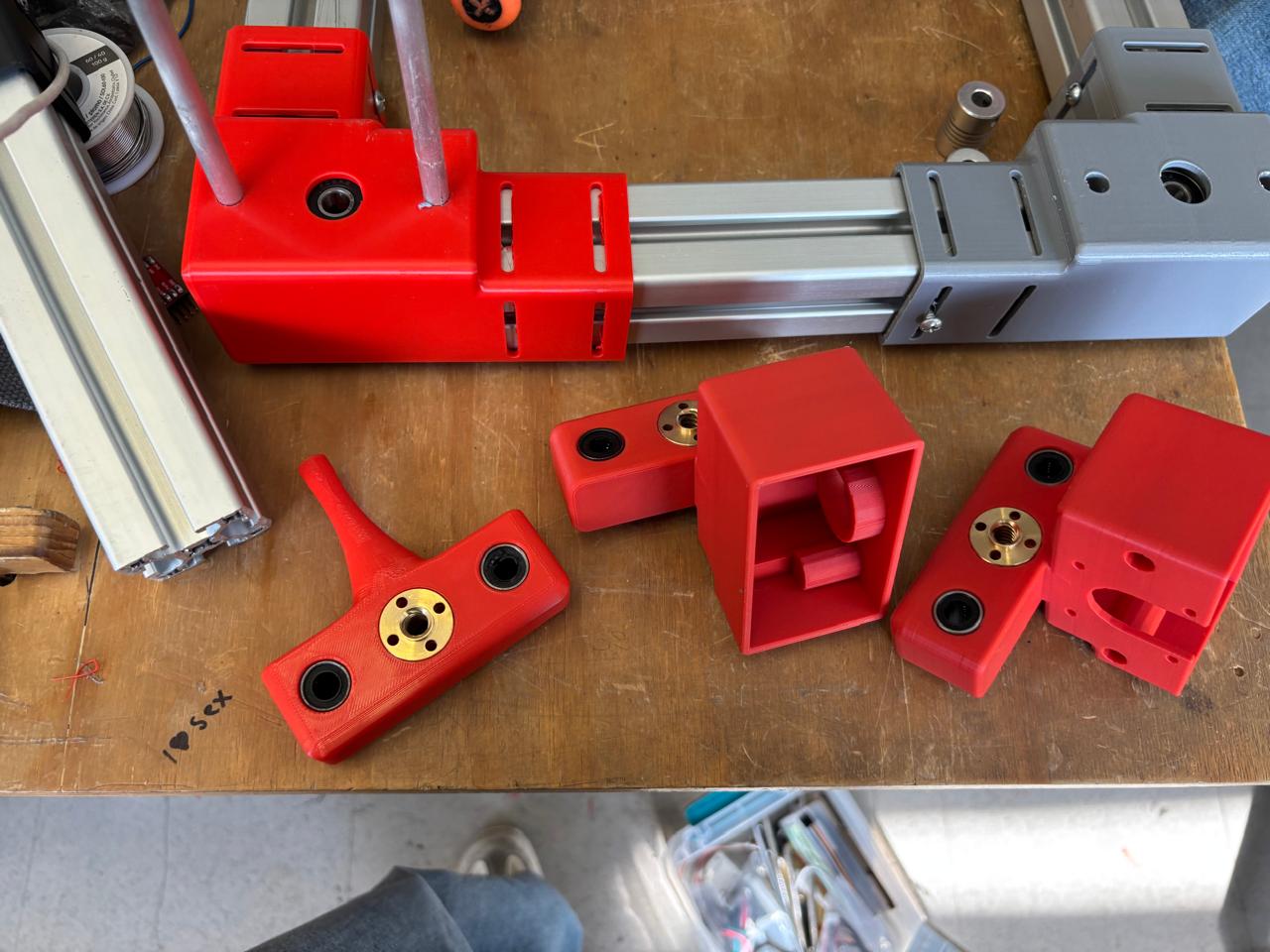
3D printing of parts
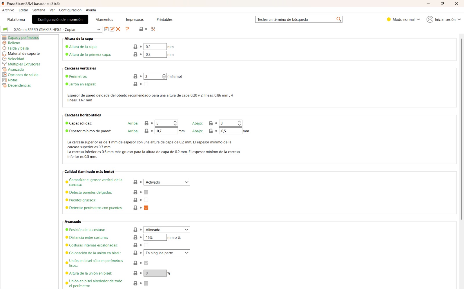
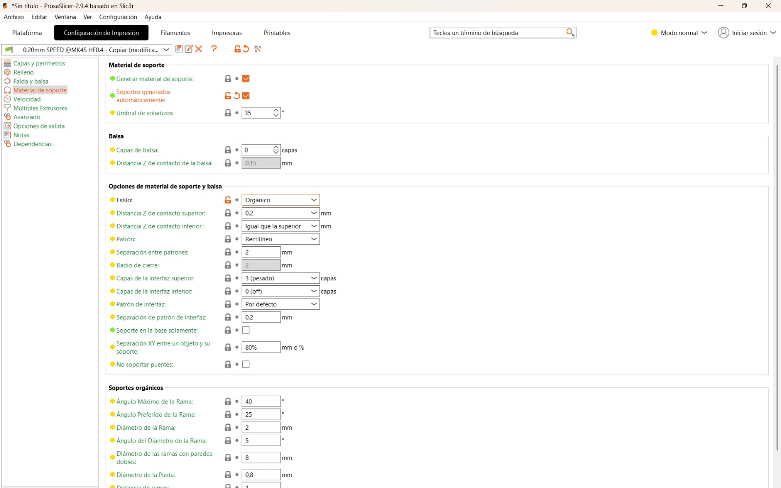
Once the assembly and the parts were received, I placed these parts into a .STL file. For their fabrication, I used a Prusa printer. From this, using the PrusaSlicer software, I configured the printing parameters. Once the parts were obtained, it was verified that they corresponded to the size of the profiles. Once all the parts were obtained, the assembly began.
Machine assembly
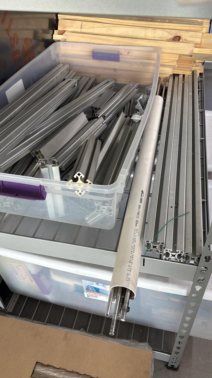
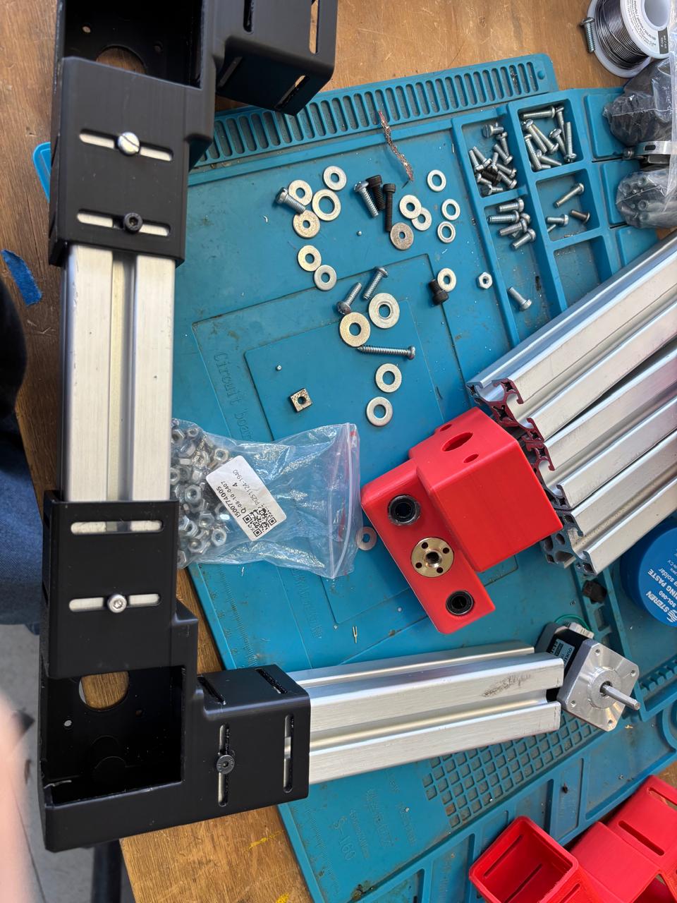
First, I obtained the necessary materials for the construction of this machine. In our case, I used the following list:
| Material | Quantity | Use |
|---|---|---|
| M3 screws | 12 | Motor fastener |
| 7.8 mm screws | 12 | Profile fastener |
| Washers | 12 | Profile fastener |
| Nuts for 7.8 mm screws | 12 | Profile fastener |
| Stepper motors | 3 | Machine movement |
| Lead screws | 2 | Machine axes |
| 25 cm aluminum rods | 6 | Spports for machine axes |
| Bearings | 3 | Machine axis movement |
| Pinion gears | 3 | Machine axis movement |
| Linear bearings | 3 | Machine axis movement |
| Spring | 6 | For connection with motors |
Thanks to the created design and the assembly, I began to build the machine. There is no specific process to follow; however, due to the design made, for me it was important to build this machine through specific steps.
Assembly Steps
Step 1
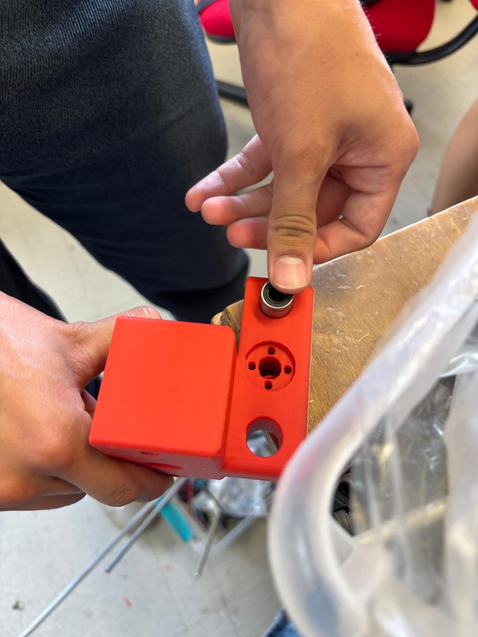
Once the parts were obtained, I verified that all of them fit correctly in their corresponding positions. Once this was done, I divided the parts into the motor side, the front side, and the parts corresponding to the Y axis.
Step 2
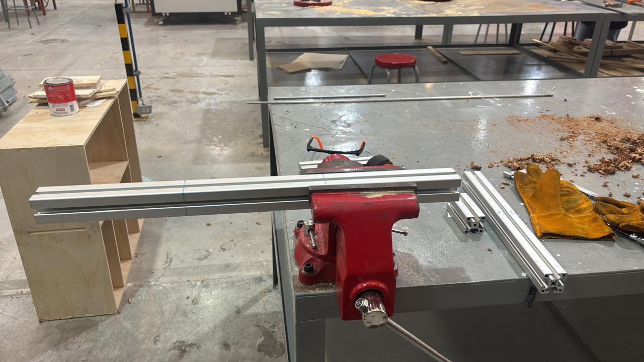
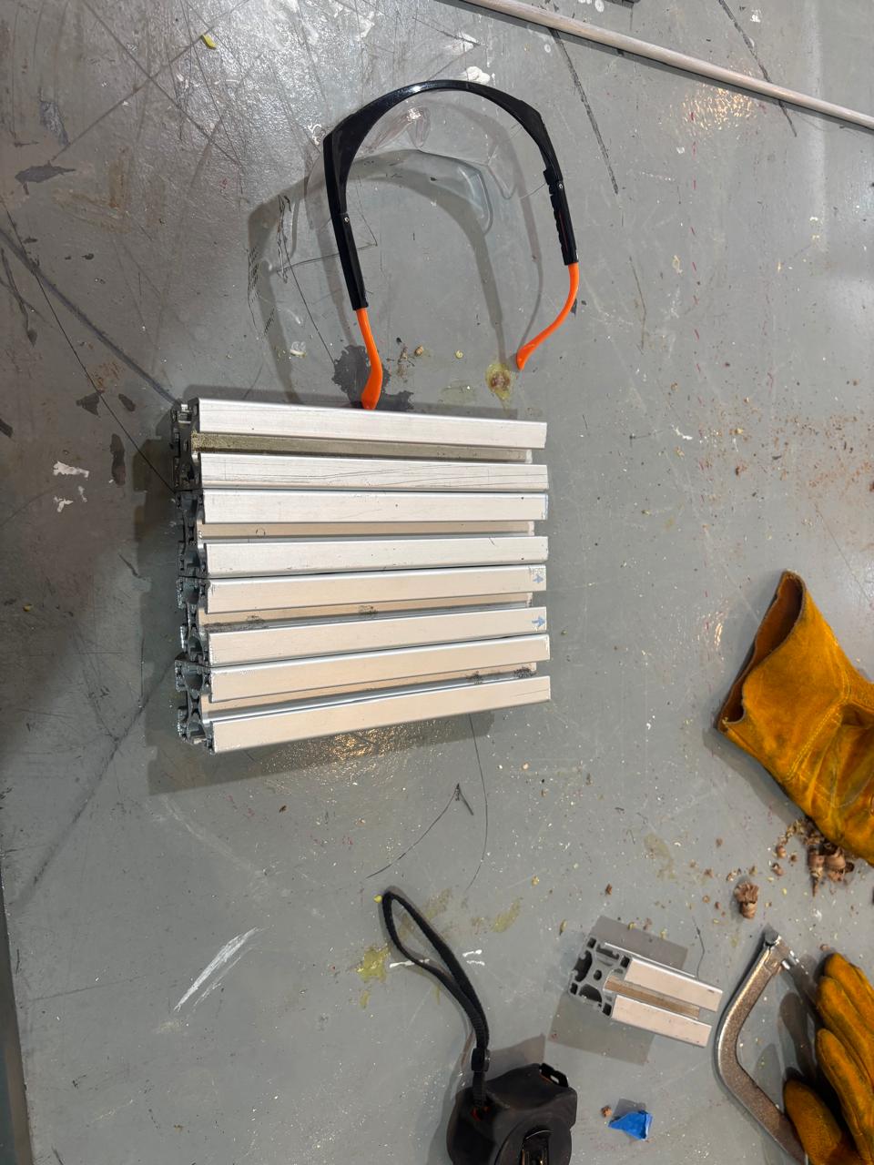
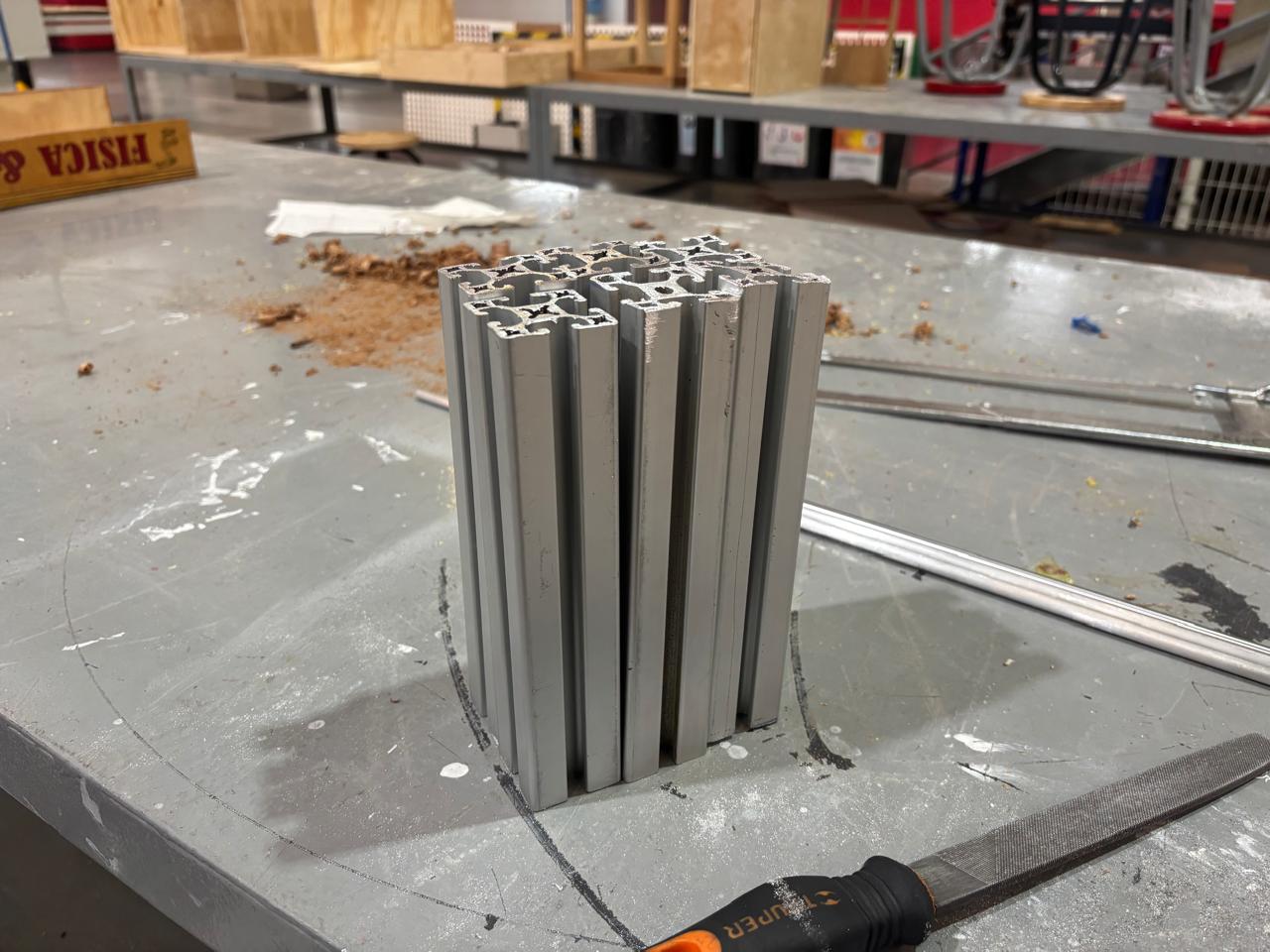
I began by taking the profiles and cutting them to a length of 200 mm; afterwards, they were sanded on the lower part so that their bases were flat. Once this was done, they began to be joined with the parts.
Step 3
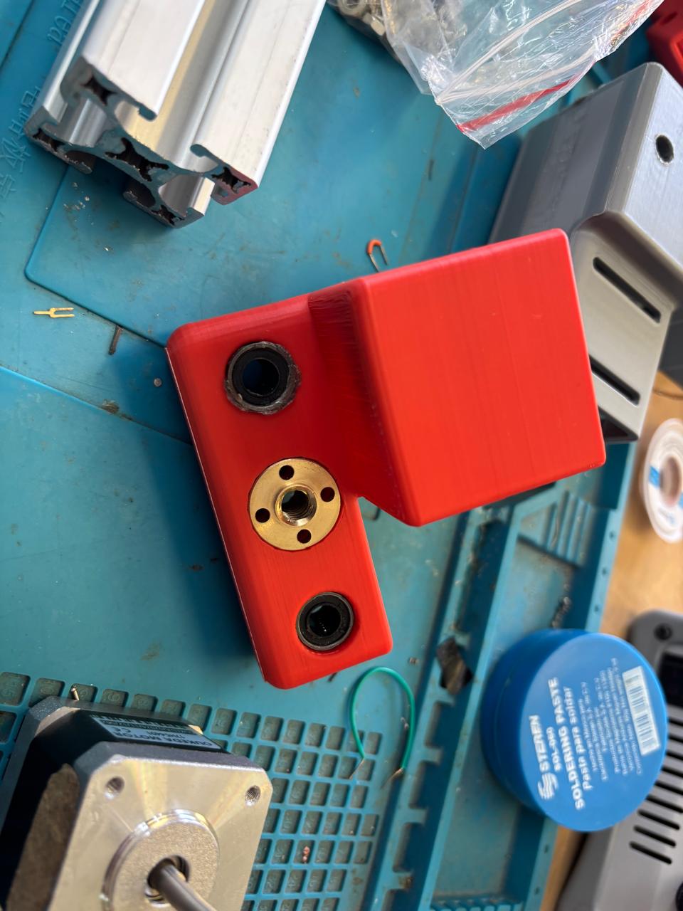
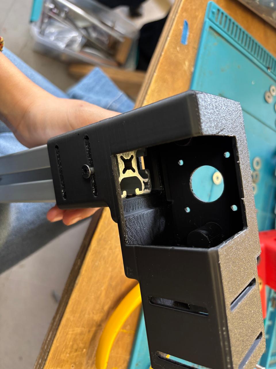
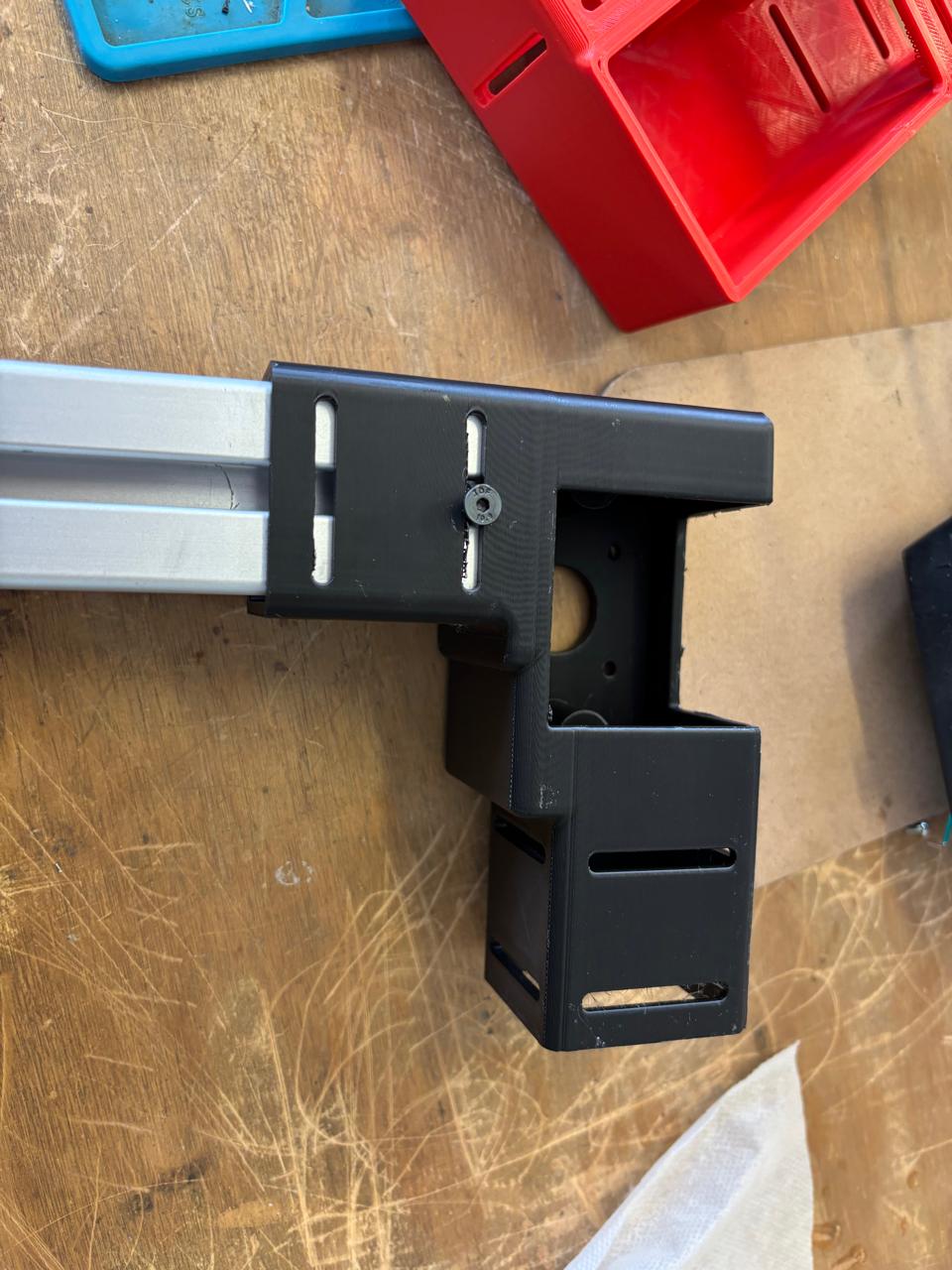
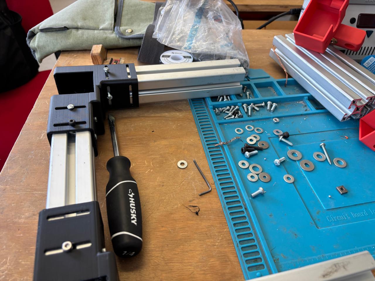
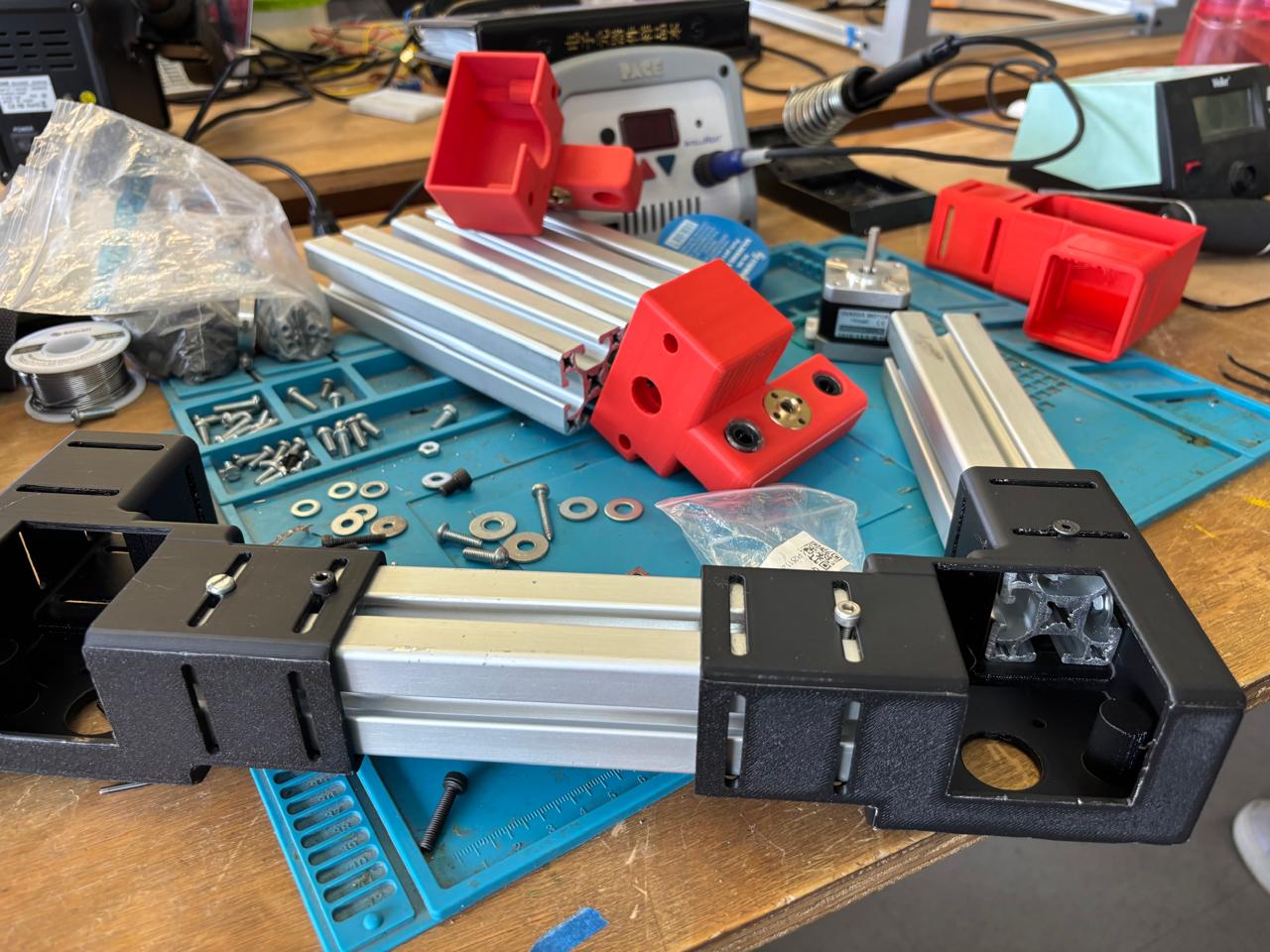
The first part of the machine was assembled. Two profiles were placed on the sides of the parts corresponding to the motors. These parts were designed so that they would fit with the profiles by placing a screw and, underneath the part, a washer to be tightened by a nut. In this way, a screwdriver was used and the parts were adjusted. Afterwards, the other part for the other side of the motor was joined and these steps were repeated.
Step 4
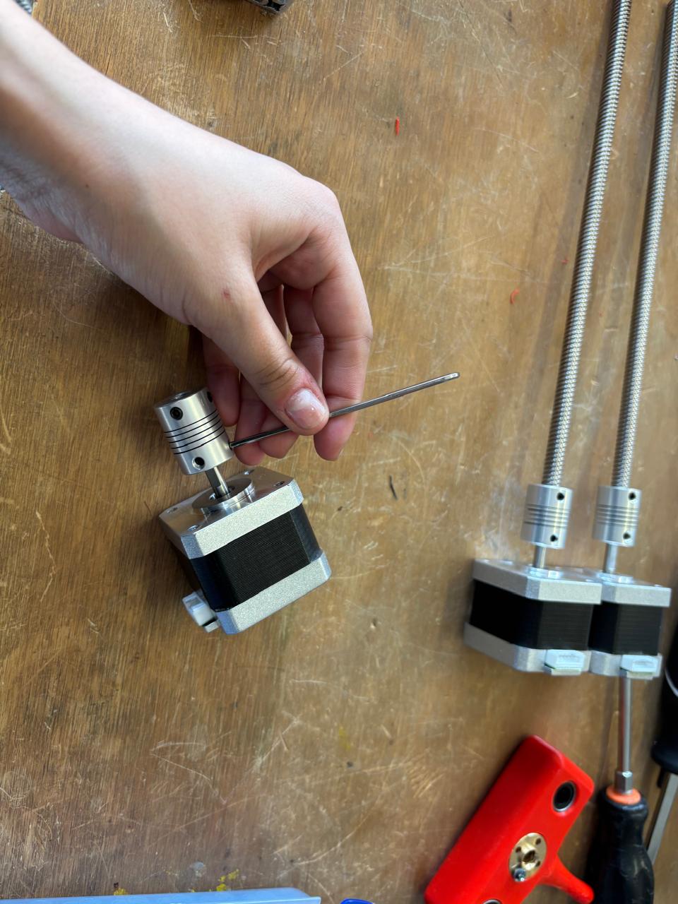
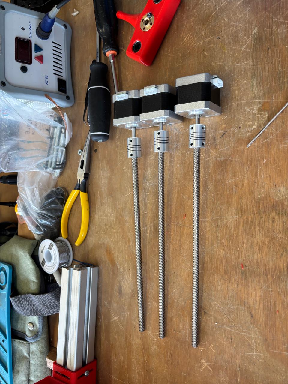
I joined the motors with their respective lead screws and the corresponding springs. After that, I placed the motors in the 3D parts and fixed them with their corresponding screws.
Step 5
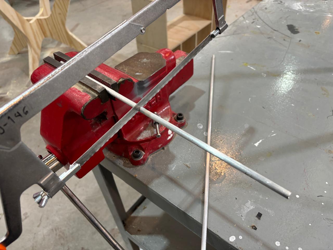
Once this was done, the rods that would serve as support for movement on the X axis were cut, that is, where the machine would slide. It was considered in the CAD design that they would have a length of 200 mm; however, the distance taken by the springs placed on the motor was considered, so they were cut to a length of 250 mm. Finally, these rods were placed in the corresponding parts. In this way, the first phase of assembly of the parts corresponding to the motors of the X axis was completed.
Step 6
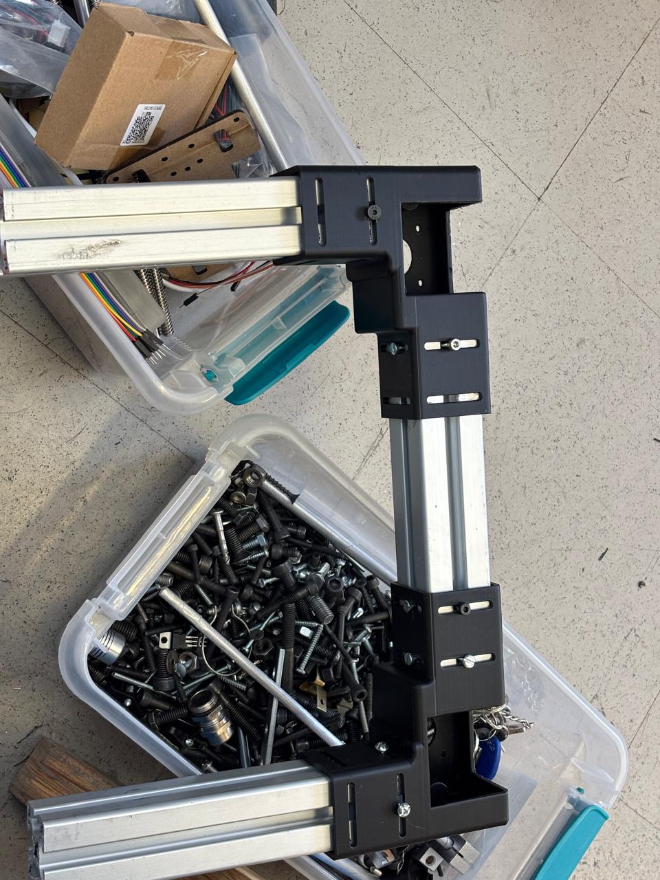
The process of step 3 began to be repeated, where only one profile was joined to the corner parts, since in this way it is much easier to handle the machine.
Step 7
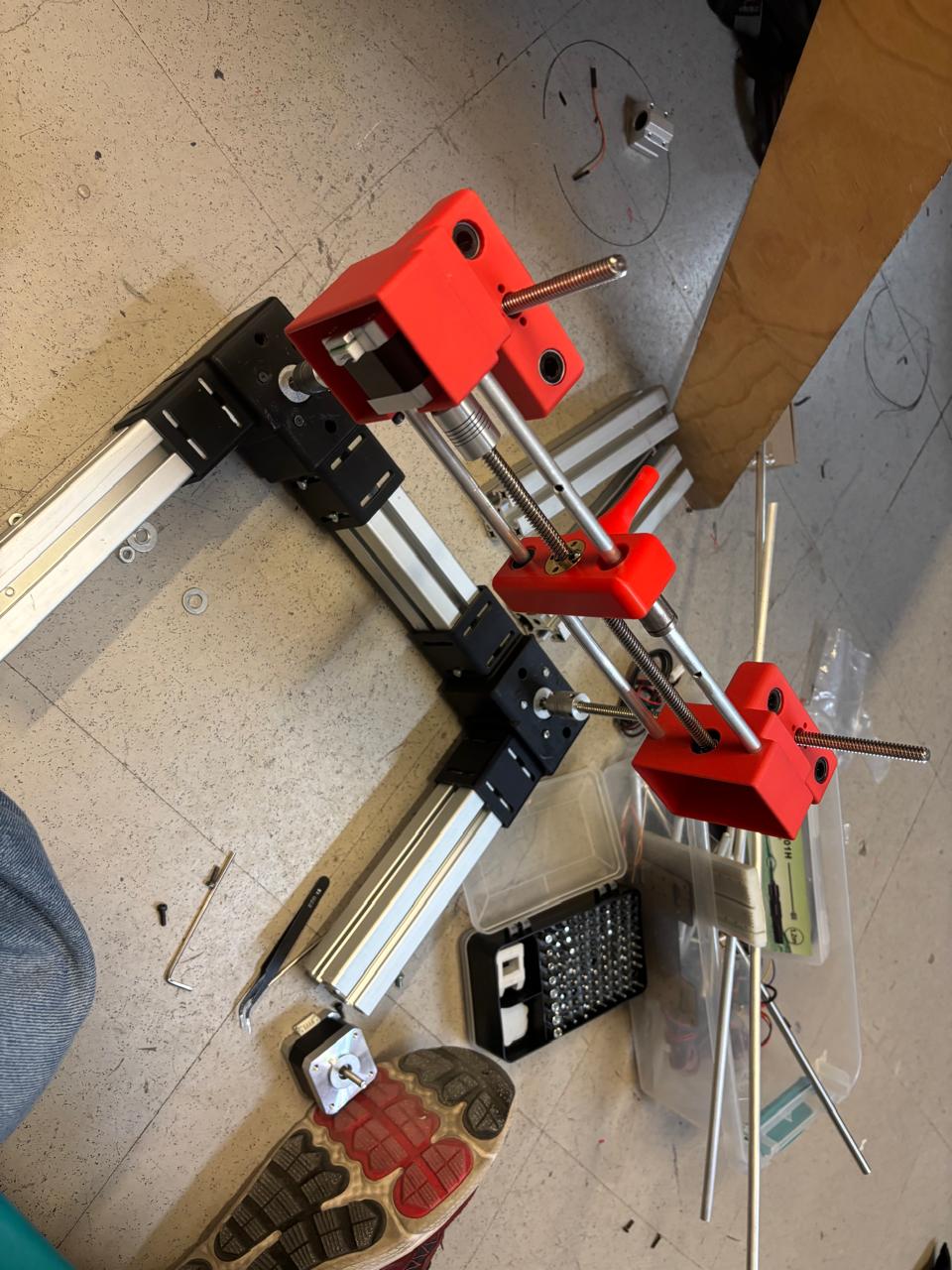
The second part of the assembly began, which was the placement of the parts corresponding to the Y axis. In this way, their corresponding washers were placed on the parts and they were inserted through the support rods and lead screws. Once placed, these parts were joined with their corresponding rods. In this way, the second part of the assembly was completed.
Step 8
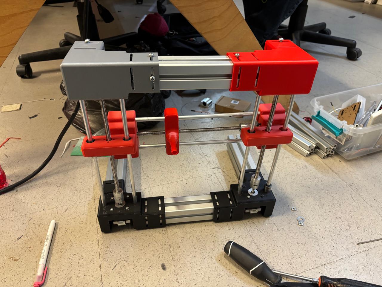
Finally, since step 6 had been done, this part of the machine was taken and finished being adjusted with the rest of the machine. Lastly, the two remaining profiles were placed to provide support to the machine.
Step 9
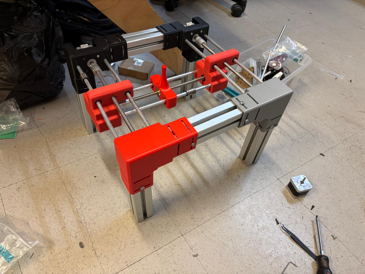
It was verified that the movement of the machine was smooth and that there was no problem for its operation.
In this way, the total assembly of the machine was completed, giving this result.
Once all parts of the team process were concluded, this was the performance of the machine.
Finally, for the group assignment for this week, you can find the information here