
Final project
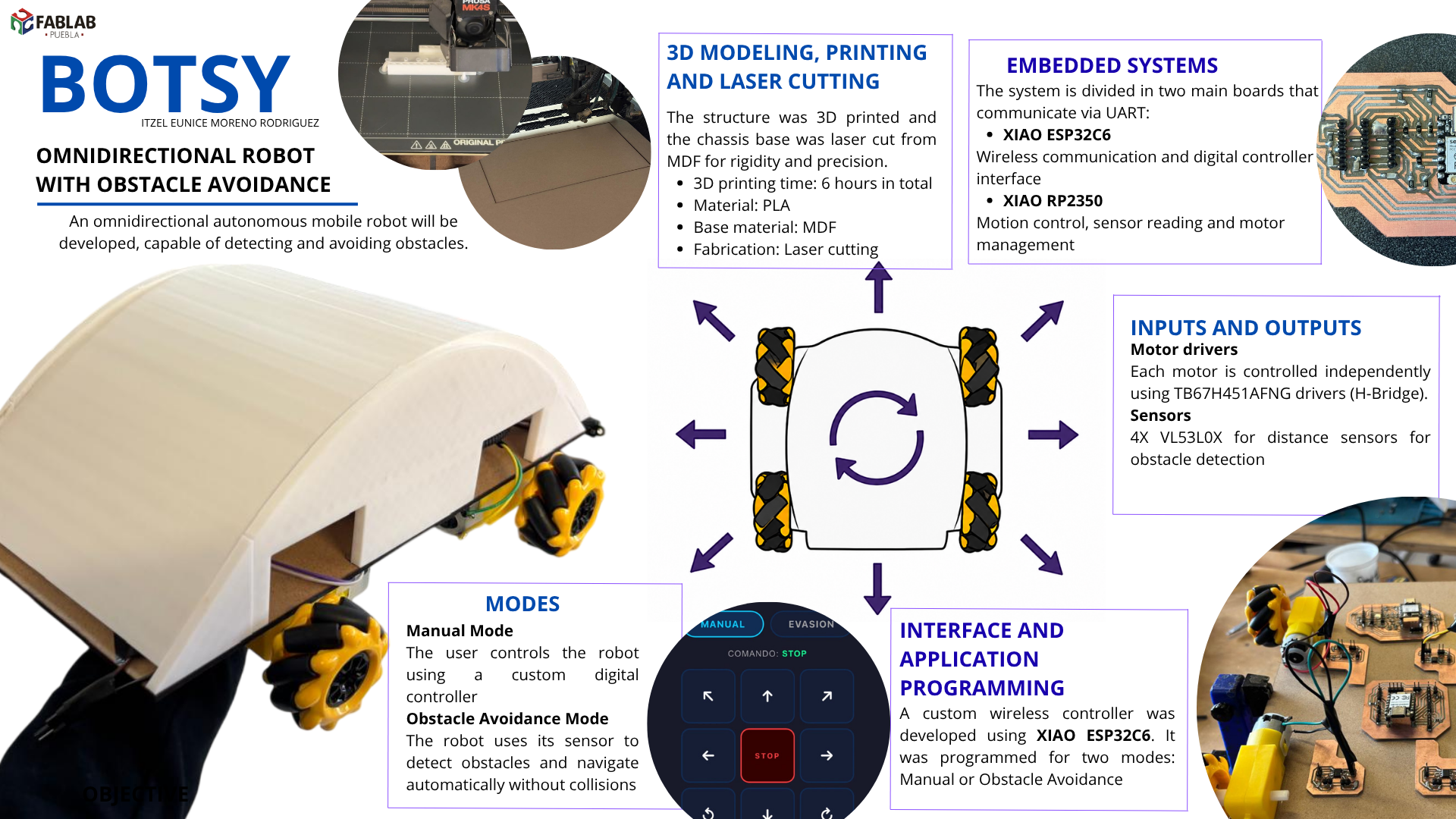
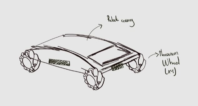
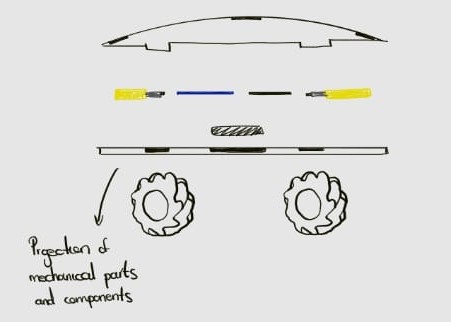
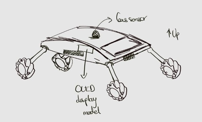
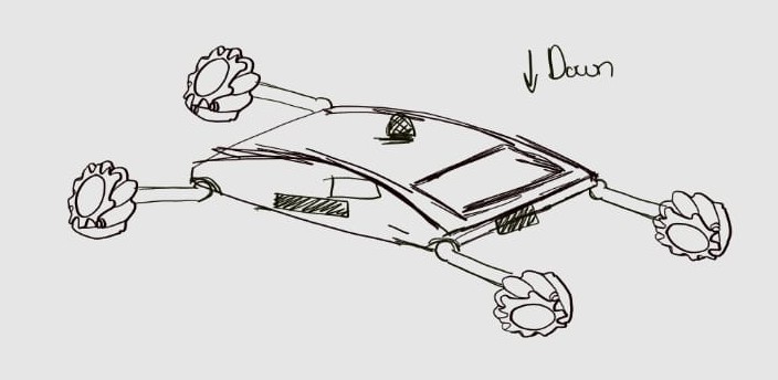
An omnidirectional autonomous mobile robot will be developed, capable of detecting and avoiding obstacles. The system is designed to operate on solid, flat, and stable surfaces. Figure 1 presents the initial conceptual design of the autonomous mobile robot.
The motivation for this project arises from a strong personal interest in robotics, particularly in the field of space robotics. This work is conceived as an opportunity to consolidate fundamental knowledge in mechanics, electronics, and programming, as well as to apply these skills in the design and construction of a functional autonomous vehicle.
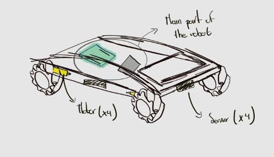
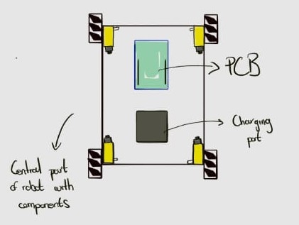
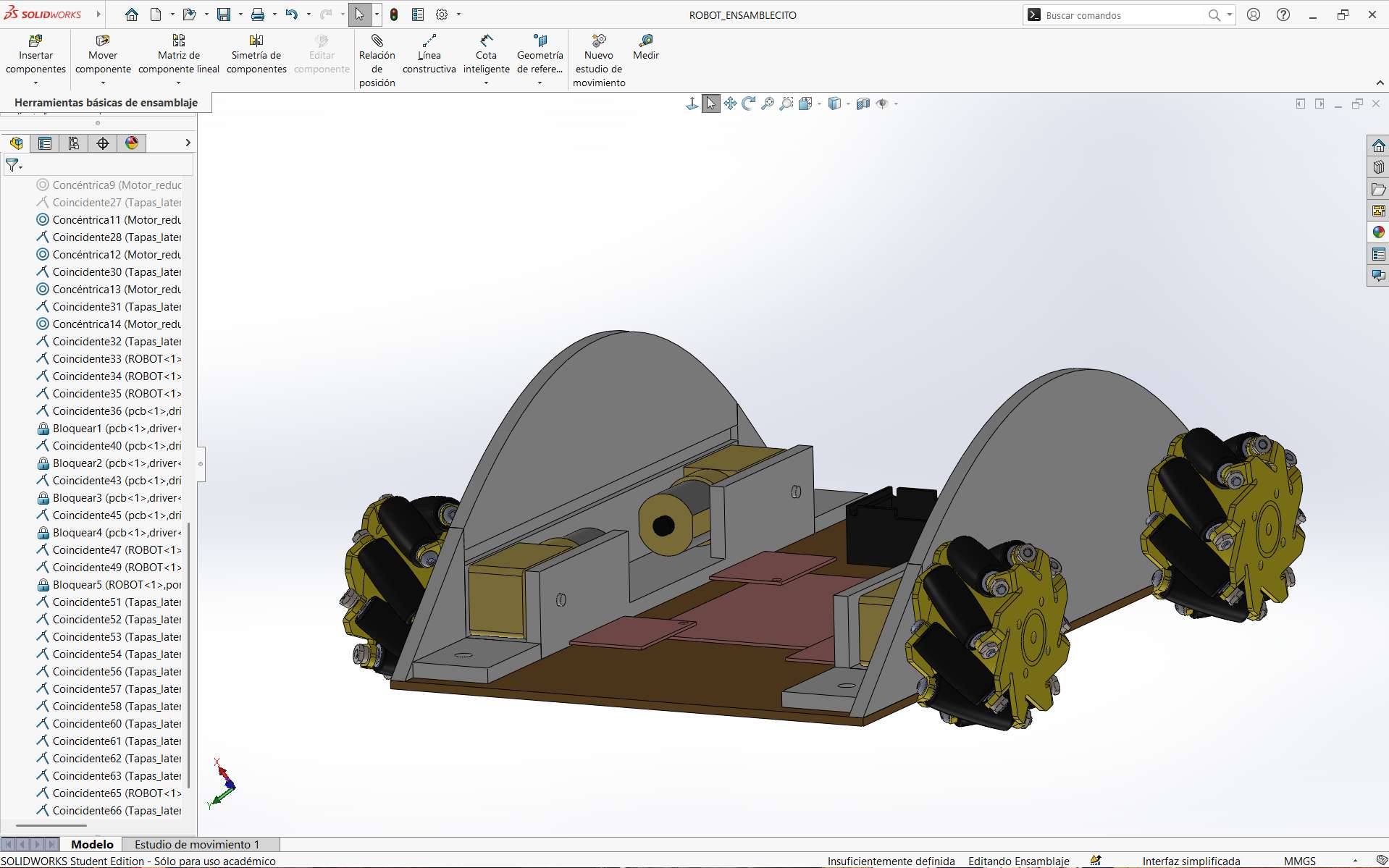
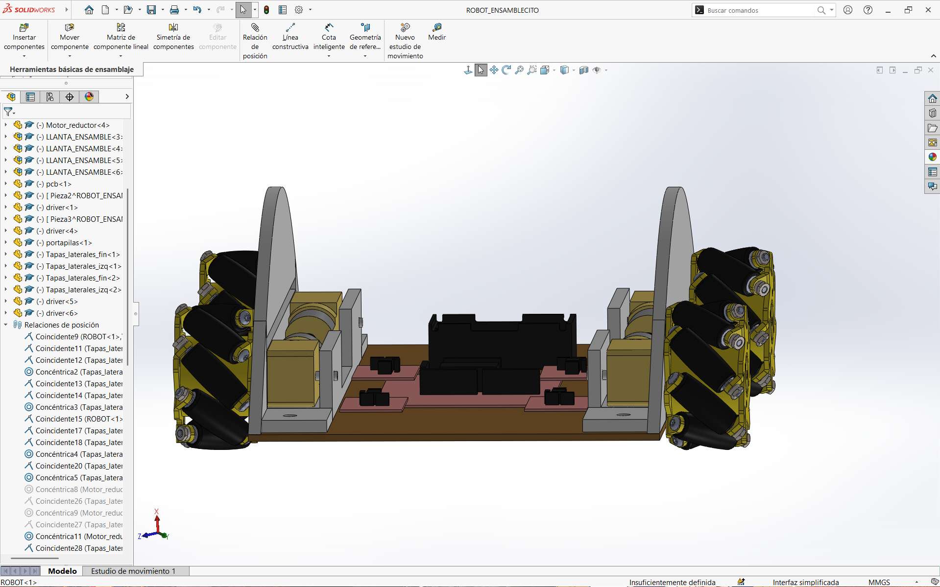
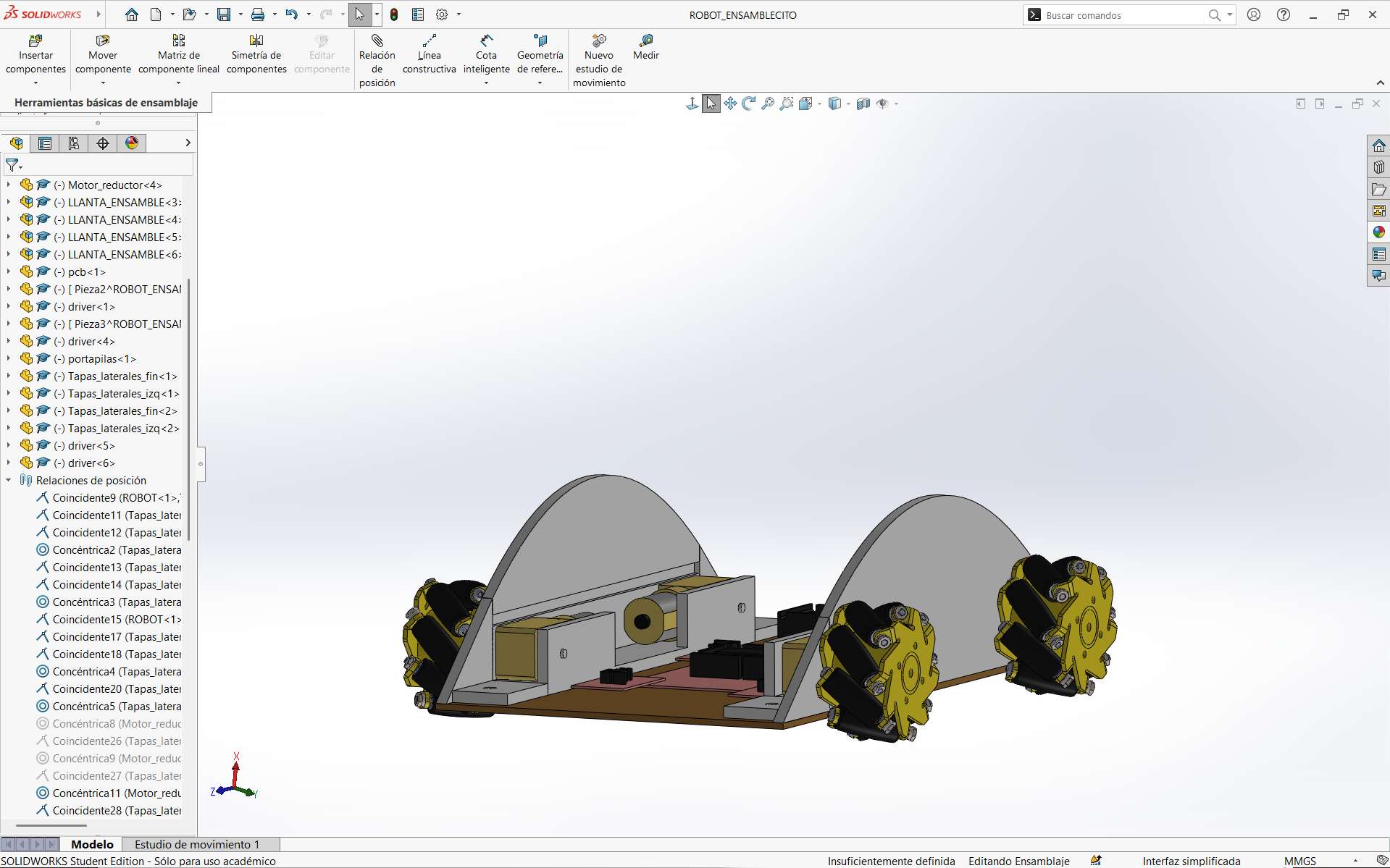
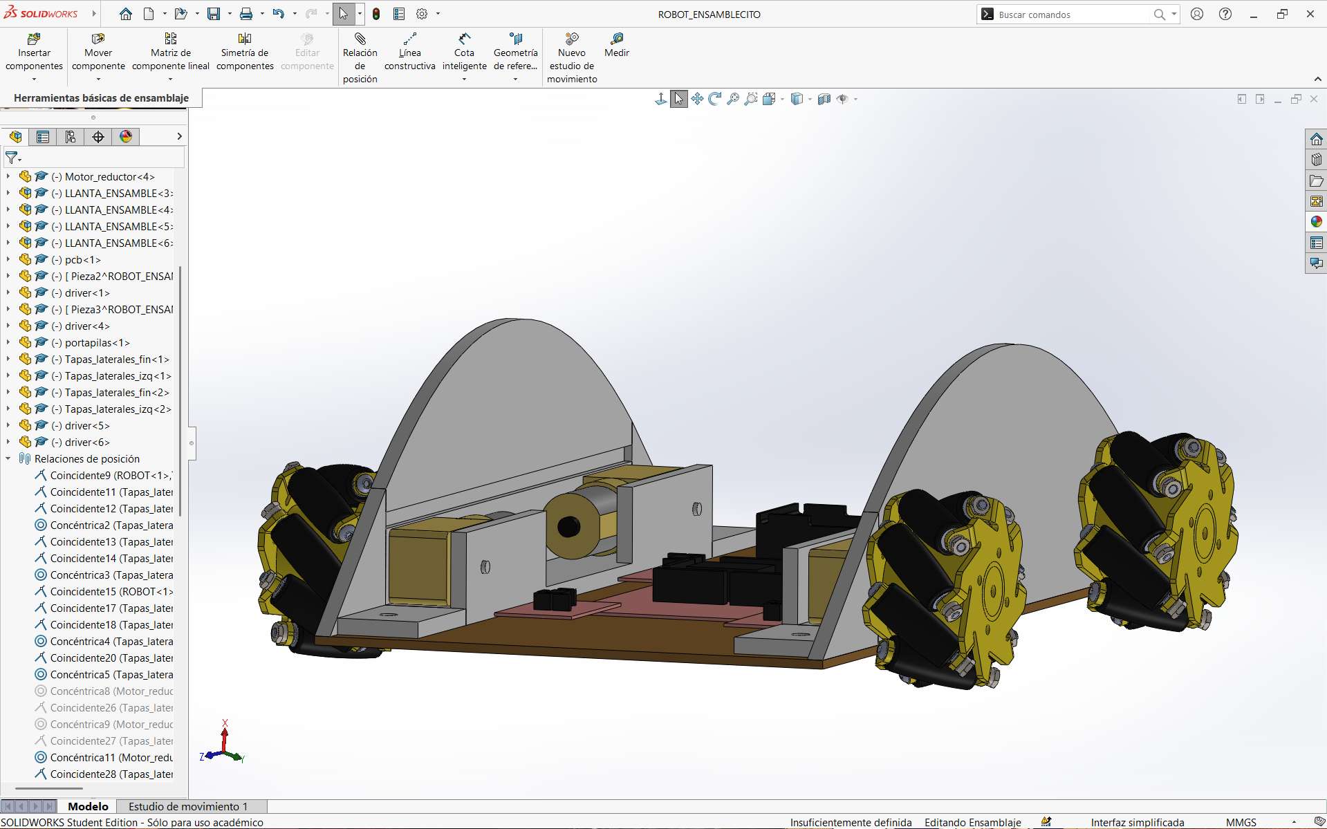
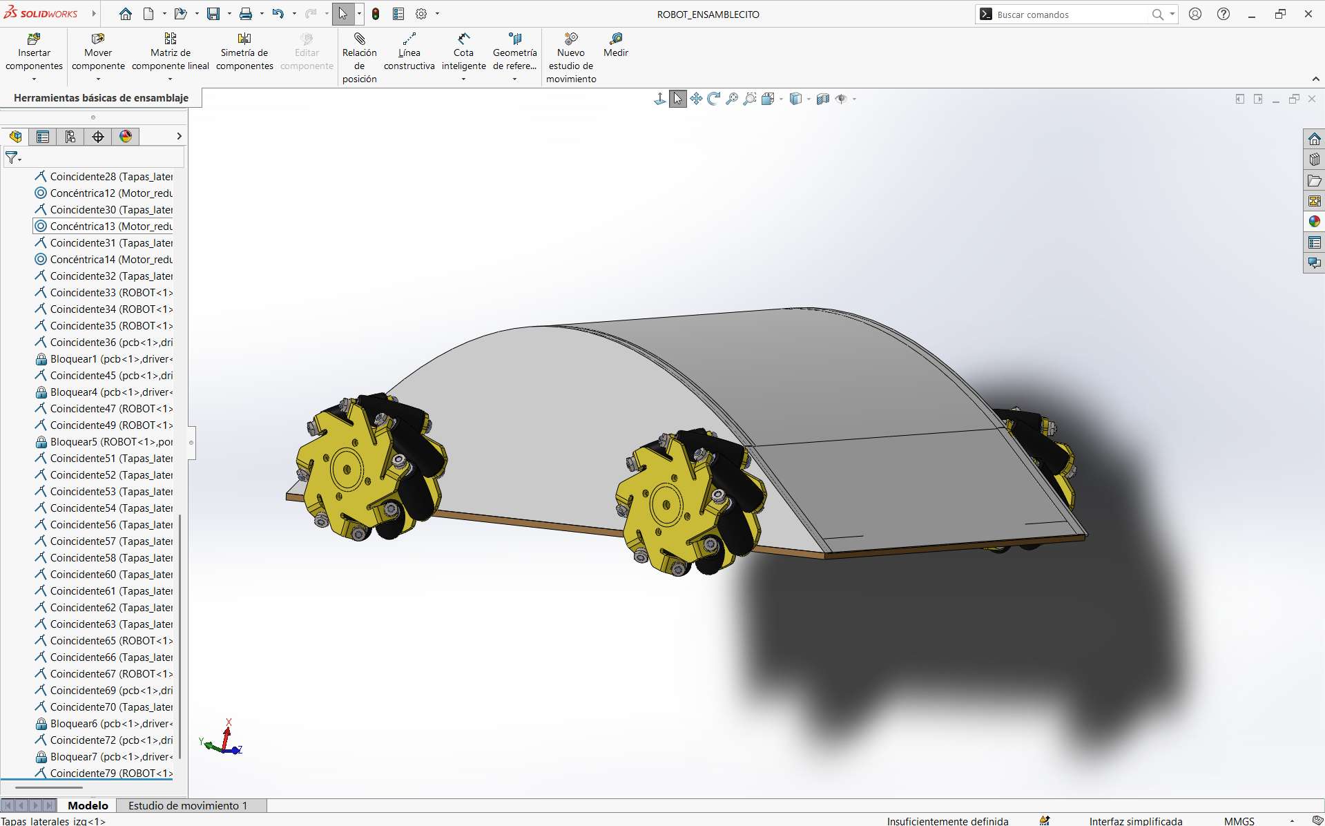
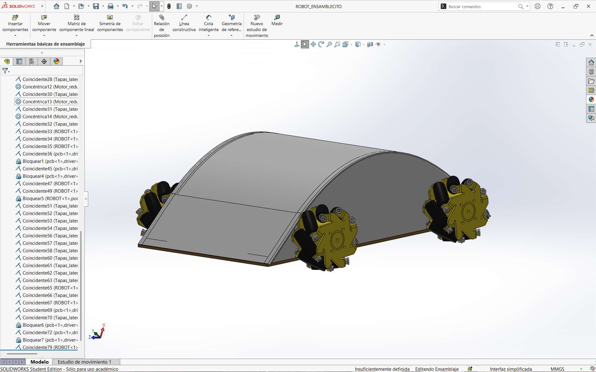
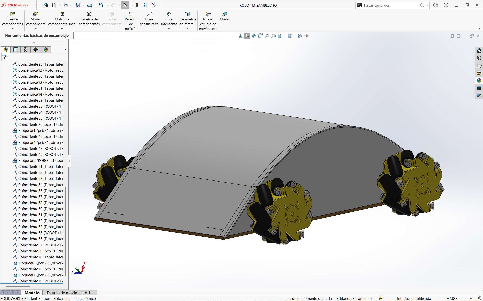
The robot will be equipped with four mecanum wheels, which enable movement in any direction depending on the motion applied to each individual wheel. These wheels will be coupled to TT DC motors and complemented with sensor systems located on the lateral, frontal, and rear sections of the autonomous vehicle. Figure 2 shows the overall robot design with the main components integrated. Figure 3 presents a top view of the robot chassis, while Figure 4 illustrates an exploded view highlighting the central components of the system.
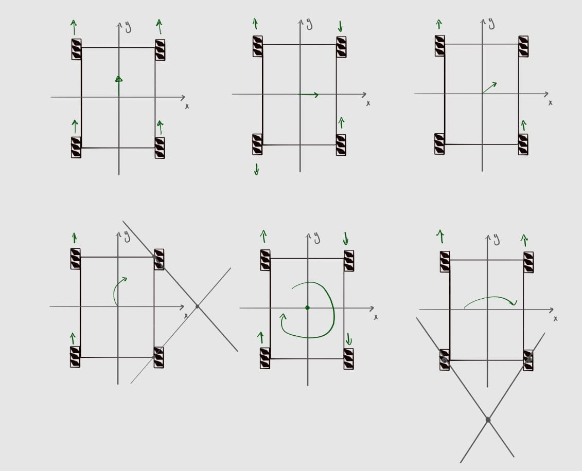
Finally, Figure 5 shows the operation of the robot's movement according to the type of motion imparted to its wheels. This information was obtained from Motion Dynamics.
Preliminary Bill of Materials
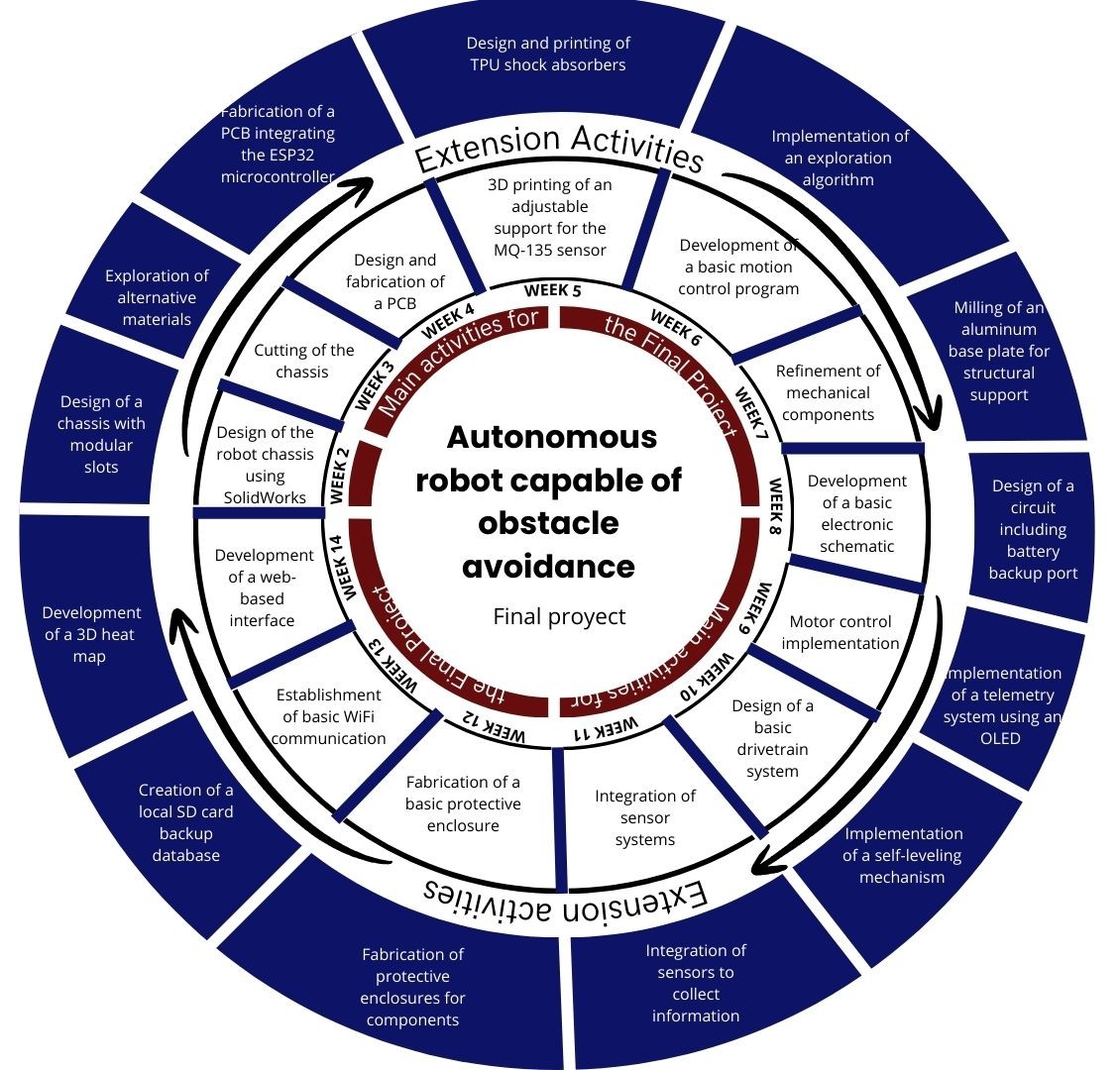
I wrote a general schedule of activities to organize myself better
| Component | Quantity | Cost (MXN) | Application |
|---|---|---|---|
| TT DC Motor | 4 | $59 | Robot locomotion |
| L298N H-Bridge Motor Driver | 1 | $90 | Control of motor speed and rotation direction |
| Rotary Encoders | 4 | $43 | Controlled measurement of vehicle motion |
| ESP32 DevKit V1 | 1 | $124 | Main microcontroller |
| HC-SR04 Ultrasonic Sensor | 3 | $53 | Obstacle detection |
| LM7805 Voltage Regulator | 1 | $48 | Voltage regulation for motors and sensors |
| AMS1117-3.3 Voltage Regulator | 1 | $12 | Voltage regulation for sensors |
| Male/Female Headers | 1 set | $350 | Electrical connections |
| Dupont Cables (MM, MF, FF) | Various | $59 | Electrical connections |
| Rechargeable Battery (2500 mAh) | 2 | $189 | Power supply |
| Power Switch | 1 | $29 | System power on/off |
| Double-sided Copper Board | 10x10cm | $392 | PCB fabrication |
| SMD Resistors 0805 | Various | $0.24 | PCB components |
| SMD Capacitors 0805 | Various | $129 | PCB components |
One of the main challenges anticipated during the development of this project is the programming and electronic design of the robot. This is primarily due to the fact that my academic background is not directly focused on these areas, resulting in limited prior experience with the programming languages, development environments, and electronic architectures required for the system. Nevertheless, this project represents an ideal opportunity to acquire and strengthen skills that are not typically addressed within my field of study, contributing significantly to my professional development.
I wrote a general schedule of activities to organize myself better
| Fablab Week | Main Tasks | Estimated Time |
|---|---|---|
| Week 1. Project management |
| 2-3 days |
| Week 2. Computer Aided Design |
| 2-3 days |
| Week 3. Computer Controlled Cutting |
| 2-3 days |
| Week 4. Electronic Production |
| 3-5 days |
| Week 5. 3D Scanning and printing |
| 2-3 days |
| Week 6. Embedded Programming |
| 3-5 days |
| Week 7. Computer Controlled Machining |
| 3-4 days |
| Week 8. Electronics Design |
| 3-4 days |
| Week 9. Output Devices |
| 2-3 days |
| Week 10. Mechanical Design |
| 2-3 days |
| Week 11. Input Devices |
| 3-4 days |
| Week 12. Molding and Casting |
| 3-4 days |
| Week 13. Embedded Networking and Communications |
| 4-5 days |
| Week 14. Interface and Application Programming |
| 4-5 days |
Mecanum wheels have free rollers positioned at 45° relative to the wheel axis. Independently controlling each of these wheels allows different rotation combinations, enabling the robot to move along the X and Y axes, rotate in place, and perform any simultaneous combination of these movements.
Based on the initial design, a potential project extension is proposed, focused on the development of a gas-mapping robot operating within a controlled environment. This extension is conceived as an enhancement and expansion of the base system, with potential applications in environmental monitoring and the analysis of current real-world problems.
Design for the Gas-Mapping Robot
The gas-mapping robot will be based on the initial autonomous vehicle design, with modifications to integrate additional sensors and functionalities. The main components of the system will include:
- Chassis: Adapted to accommodate additional sensors and ensure stability during operation.
- Microcontroller: ESP32 or similar, capable of handling multiple sensor inputs and data processing.
- Sensors: Integration of gas sensors such as MQ-135 (smoke), SGP30 (CO₂/VOCs), and DHT22 (temperature and humidity) for comprehensive environmental monitoring.
- Data Storage: Implementation of local data storage using an SD card module, with potential WiFi connectivity for real-time data transmission.
- Power Supply: Enhanced battery system to support additional components and ensure extended operation time.
Schedule for Future Work: Robot Upgrade to Gas-Mapping System
| Fablab Week | Main Tasks | Estimated Time |
|---|---|---|
| Week 1. Project management |
| 1 day |
| Week 2. Computer Aided Design |
| 2-3 days |
| Week 3. Computer Controlled Cutting |
| 1-2 days |
| Week 4. Electronic Production |
| 4-5 days |
| Week 5. 3D Scanning and printing |
| 2-3 days |
| Week 6. Embedded Programming |
| 5-6 days |
| Week 7. Computer Controlled Machining |
| 2-3 days |
| Week 8. Electronics Design |
| 4-6 days |
| Week 9. Output Devices |
| 3-5 days |
| Week 10. Mechanical Design |
| 3-5 days |
| Week 11. Input Devices |
| 3-5 days |
| Week 12. Molding and Casting |
| 2-5 days |
| Week 13. Embedded Networking and Communications |
| 3-7 days |
| Week 14. Interface and Application Programming |
| 4-5 days |
Bill of Materials for Future Work
| Component | Quantity | Cost (MXN) | Application |
|---|---|---|---|
| MQ-135 Gas Sensor | 1 | $53 | Gas and smoke detection |
| SGP30 Sensor | 1 | $199 | CO2 and VOC detection |
| DHT22 Sensor | 1 | $135 | Temperature and humidity measurement |
| SD Card Module | 1 | $49 | Local data storage |
| OLED Display 0.96" | 3 | $103 | Visualization of robot data |
| Motor Rotary Encoders | 2 | $165 | Estimation of traveled distance |
| SD Card Reader Module | 1 | $245 | Local data storage |
| MicroSD Card 16 GB | 1 | $57 | Data storage |
| Acrylic Sheets | Various | $91 | Enclosure for controlled environment |
Spiral development
As previously discussed, this autonomous mobile robot presents multiple opportunities for future improvement and expansion. Based on this perspective, a Spiral Development is proposed as a visual tool to outline potential milestones and long term development goals, assuming the successful completion of the core project objectives.
Project Progress
As of the submission of this report, the project is in the early stages of development.
3D Modeling, Printing and Laser cutting
CAD Design
For the robot design, I used SolidWorks. This program allowed me to create the main parts of the car. These consisted of:
- Chassis
- Side supports for the motors
- Top cover
In this way, based on the approximate dimensions of the boards and the size of the motors that would be used, the system was designed in parts and later assembled. The tools used were learned during week 2. From this, the following process was carried out:
- Base: The estimated spaces that would be used are placed.
- Side design: The side supports are built considering the size of the motors, as well as spaces for screws and fixing the system.
- Stepper motor design: The stepper motor is designed to provide the necessary torque and speed for the robot's movement.
- Mecanum wheel design: The mecanum wheels are designed to allow the robot to move in any direction.
- Top cover design: The top cover is designed to protect the internal components of the robot.
Assembly
Finally, based on the designed parts, the following result was obtained:
This design allowed me to create my files in DXF format for the robot base and STL format for the side and top parts of the car, this being the first part that makes up the project from the design area.
Piece Dimension Testing
Side Supports
To carry out the tests of the car chassis, I first sent the motor bases or supports for 3D printing. In this way, the following result was obtained:
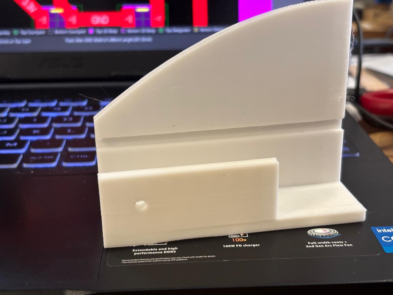
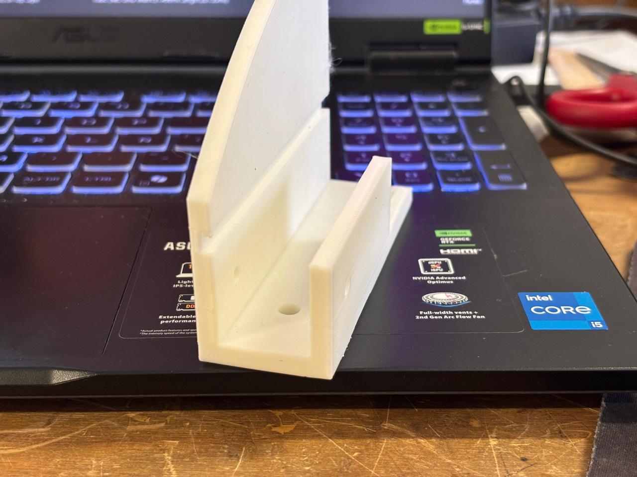
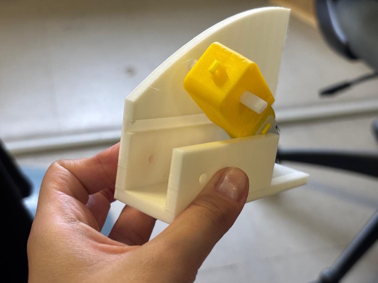
As can be seen, the motors fit very tightly, therefore it was decided to increase the spacing size between the walls, as well as the hole space for the motor output, and reduce the thickness of the base by half (also considering the size of the wheels).
3D printing process
After validating the dimensions and fit of the designed parts through several tests, I proceeded to manufacture all the components using a PRUSA 3D printer. The following printing parameters were used:
My prints required approximately six hours in total to complete, as the project consisted of multiple components and several of them occupied a significant portion of the printer's build volume. Once all the pieces were printed, they were inspected to verify dimensional accuracy and proper assembly with the rest of the system.
Laser Cutting
The chassis required a rigid base capable of supporting the electronic and mechanical components of the robot. After evaluating different options, I selected MDF as the construction material because it is readily available, cost-effective, and provides sufficient structural rigidity for the application.
Additionally, laser cutting allowed me to manufacture the chassis quickly and accurately, ensuring precise dimensions and repeatable results. This process was particularly useful because it enabled the fabrication of clean and consistent cuts while reducing manufacturing time.
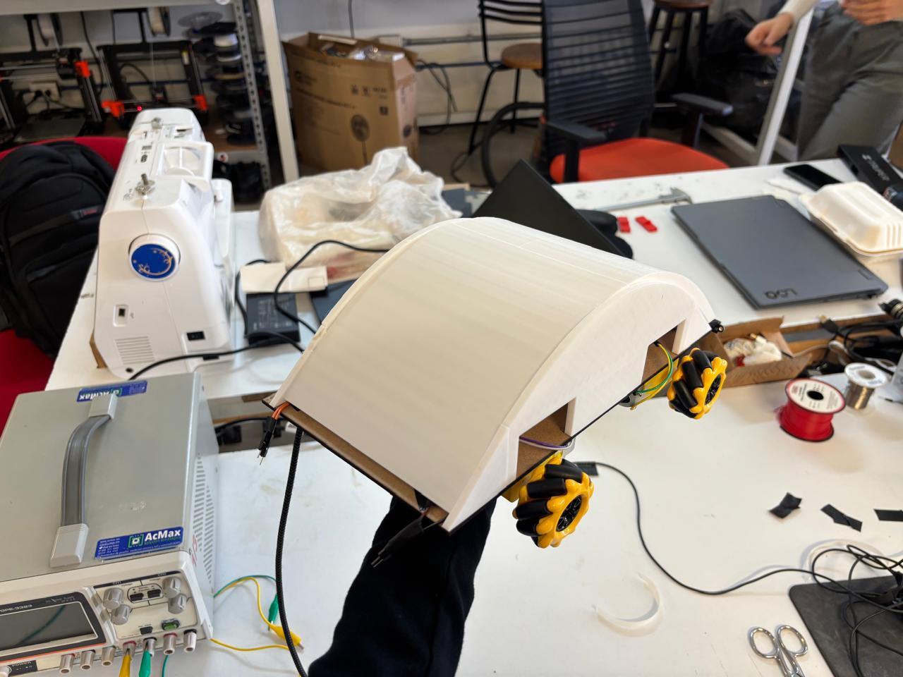
Final results
Here is my final result
Embedded Systems
PCB Design – Planning
A total of three PCB designs will be made.
Brain Board Design
The XIAO ESP32C6 will be used as the brain of the project. Connected to it will be the VL53L0X sensors, WiFi for XBOX controller input, QR code processing, navigation logic, and the transmission of speed or direction commands. This board will be manufactured once.
Components
- Connected sensors (3× VL53L0X)
- QR reader (GM65) – subject to change
- 4.7kΩ pull-up resistors on SDA and SCL
- 10kΩ pull-up resistors on each XSHUT
- 100nF capacitors (3 per sensor)
- 10µF capacitor (to stabilize 3.3V)
| PIN | Function | Connected to |
|---|---|---|
| D4 (SDA) | I2C data | SDA of all 3 VL53L0X + 4.7kΩ pull-up to 3.3V |
| D5 (SCL) | I2C clock | SCL of all 3 VL53L0X + 4.7kΩ pull-up to 3.3V |
| D0 | XSHUT sensor 1 | XSHUT VL53L0X #1 |
| D1 | XSHUT sensor 2 | XSHUT VL53L0X #2 |
| D2 | XSHUT sensor 3 | XSHUT VL53L0X #3 |
| D6 (TX) | UART TX | RX of GM65 |
| D7 (RX) | UART RX | TX of GM65 |
| D8 (TX2) | UART toward RP2350 | RX of RP2350 |
| D9 (RX2) | UART from RP2350 | TX of RP2350 |
| 3.3V | Power supply | VIN of all 3 VL53L0X + GM65 + pull-ups |
| GND | Ground | GND of everything |
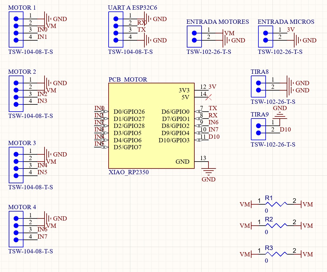
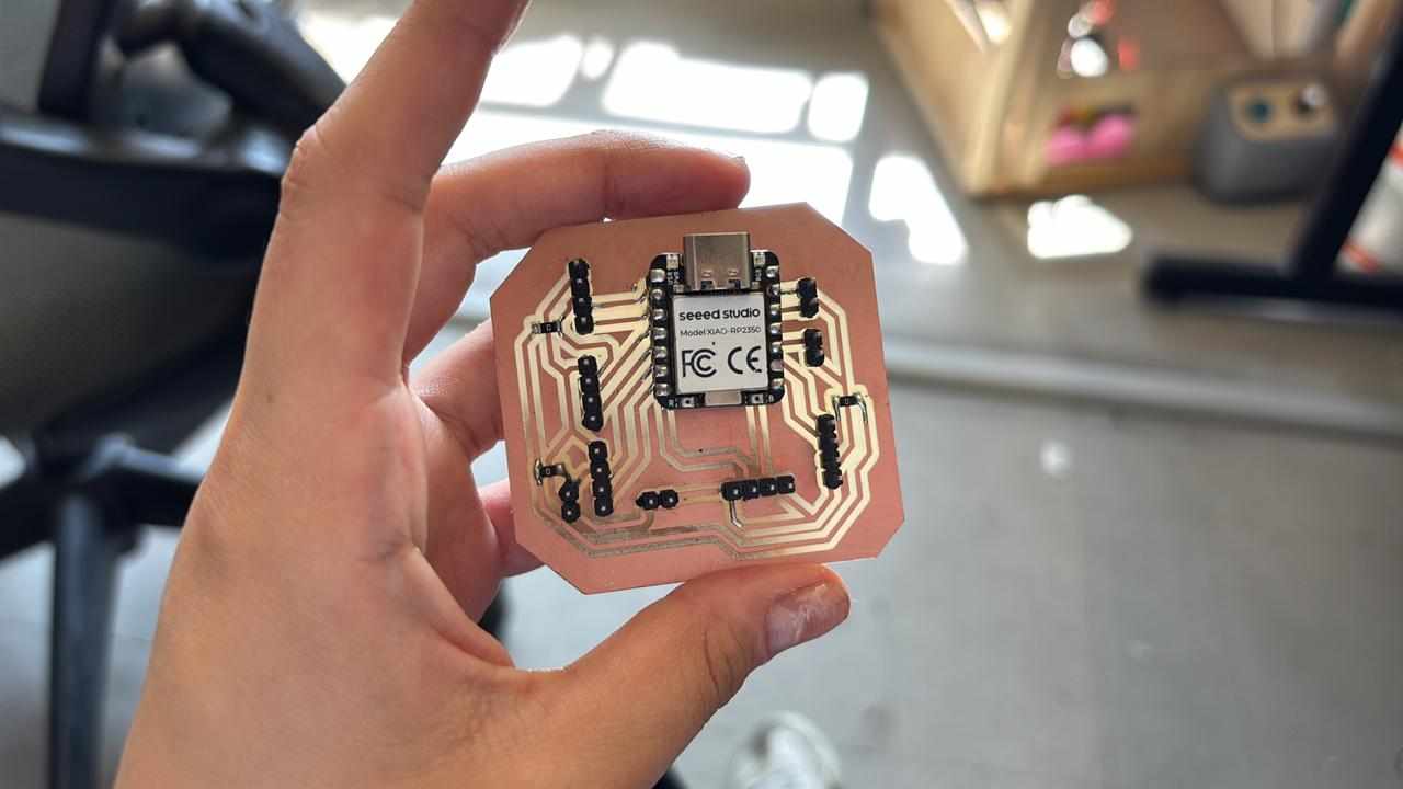
Motor Board Design
A board based on the XIAO RP2350 will be created to connect the motors and receive commands from the ESP32C6 to independently control the four motors. This board will be manufactured once.
- 100µF and 100nF capacitors in parallel on the motor power supply.
- 4-output connector toward the 4 driver boards.
| PIN | Function | Connected to |
|---|---|---|
| D0 | PWM motor 1 | IN1 driver board #1 |
| D1 | DIR motor 1 | IN2 driver board #1 |
| D2 | PWM motor 2 | IN1 driver board #2 |
| D3 | DIR motor 2 | IN2 driver board #2 |
| D4 | PWM motor 3 | IN1 driver board #3 |
| D5 | DIR motor 3 | IN2 driver board #3 |
| D6 | PWM motor 4 | IN1 driver board #4 |
| D7 | DIR motor 4 | IN2 driver board #4 |
| D8 (TX) | UART from ESP32C6 | TX of ESP32C6 |
| GND | Common ground | GND of ESP32C6 |
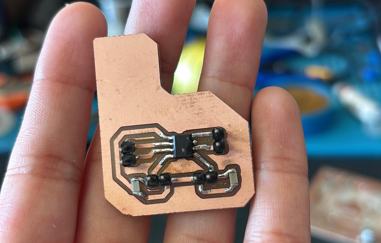
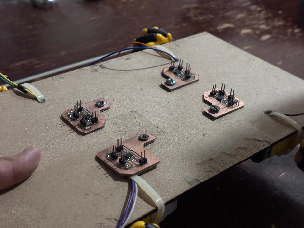
H-Bridge Driver Board Design
The DRV8251A driver will be used. This board will be manufactured 4 times, one per motor.
- DRV8251A
- 100nF capacitor between VCC and GND
- 10µF capacitor on VM (motor power supply)
| DRV8251A Pin | Connected to |
|---|---|
| IN1 | PWM from RP2350 |
| IN2 | DIR from RP2350 |
| OUT1 | Motor terminal A |
| OUT2 | Motor terminal B |
| VM | Motor power supply (3V–6V) |
| GND | Common GND |
| nSLEEP | 3.3V (always active) |
The development of the motor control system represented one of the main challenges of this project. During the initial stages, I experienced several issues related to the electronic design and component selection.
My original intention was to use the DRV8251A motor driver. However, after reviewing the electrical requirements of the motors, I determined that their operating voltage was below the minimum voltage required by the DRV8251A to function correctly. Because of this limitation, I selected the TB67H451AFNG motor driver instead.
To achieve independent control of each motor, a dedicated TB67H451AFNG was used. As an additional precaution during assembly, electrical insulating tape was placed underneath each IC to prevent accidental conduction paths or undesired electrical contacts with the supporting surface. After assembly, each driver was tested individually to verify proper operation before integrating it into the complete system.
Design with Altium
This was my procedure for creating my boards. For this, Altium was used and the previously established criteria in the tables were followed, where my schematics were the following:
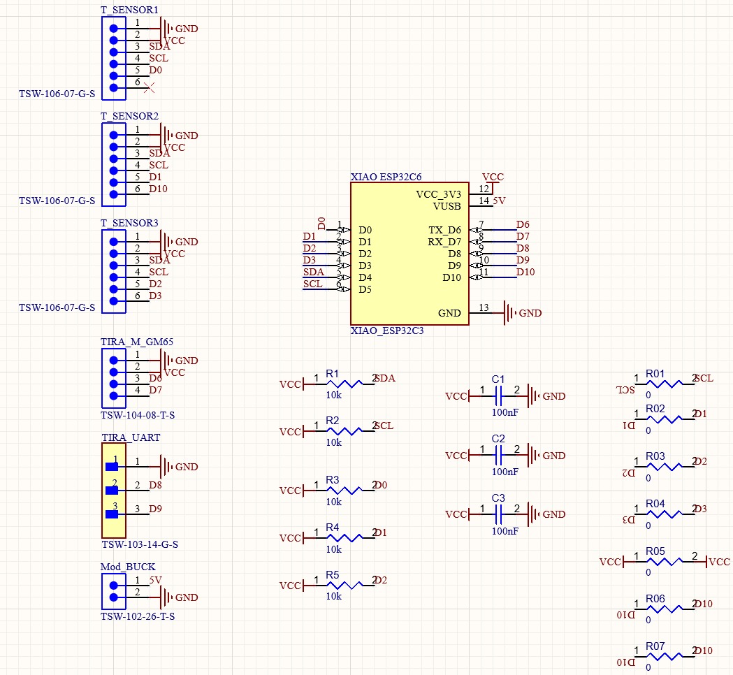
Brain Board Schematic Process
Motor Board Schematic
PCB Manufacturing
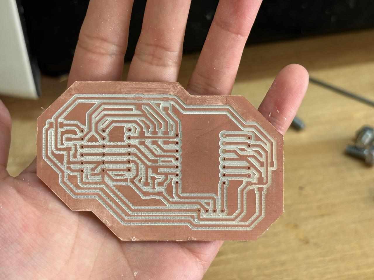
Regarding the manufacturing of my boards, once the designs were obtained, exactly the same procedure from week 8 was followed. The same parameters were used for each of the tools. In this way, the three main boards were successfully manufactured.
The procedure inside the Monofab:
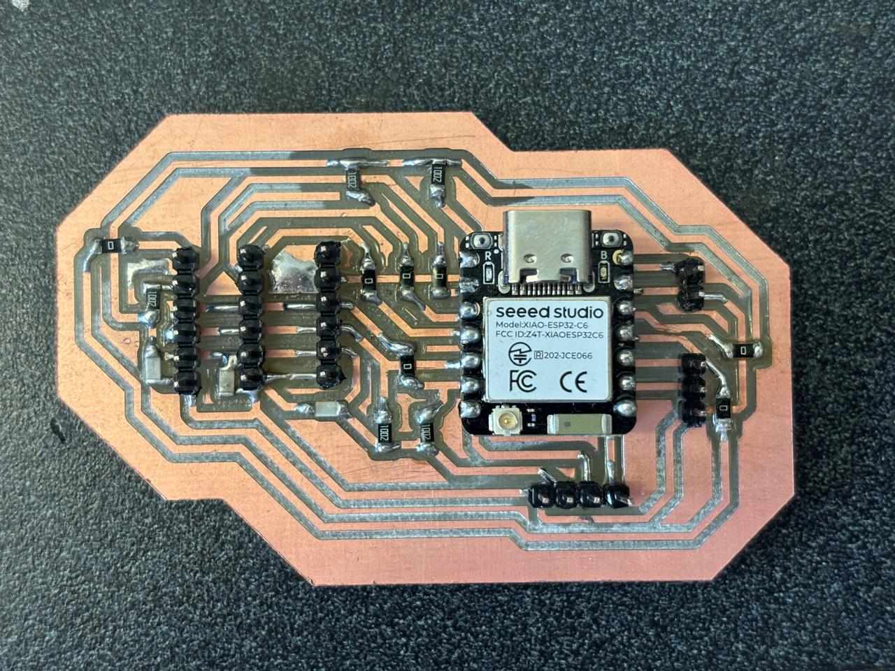
Finally, once the boards were obtained, the remaining components were soldered, where the result was the following:
Finally, this was the final result:
Inputs and Outputs
VL53L0X Sensor Testing – Individual and Combined
There are different types of distance-measuring sensors; among them is the VL53L0X. First, it was necessary to test a single sensor. For this purpose, the following code was used:
#include <Wire.h>
#include <VL53L0X.h>

#define SENSOR_SDA  6
#define SENSOR_SCL  7
#define XSHUT_PIN   2

VL53L0X sensor;

void setup() {
  Serial.begin(115200);
  Wire1.setSDA(SENSOR_SDA);
  Wire1.setSCL(SENSOR_SCL);
  Wire1.begin();
  pinMode(XSHUT_PIN, OUTPUT);
  digitalWrite(XSHUT_PIN, LOW);
  delay(10);
  digitalWrite(XSHUT_PIN, HIGH);
  delay(50);
  sensor.init(true);
  sensor.setTimeout(500);
  sensor.startContinuous();
  Serial.println("Sensor ready!");
}

void loop() {
  int distance = sensor.readRangeContinuousMillimeters();
  if (sensor.timeoutOccurred()) {
    Serial.println("Error: Timeout occurred");
  } else {
    Serial.print("Distance: ");
    Serial.print(distance);
    Serial.println(" mm");
  }
  delay(100);
}
Motion Programming
For the wheel programming, research was first conducted on the basic movements possible with the purchased wheel type. Based on these observed movements, a code was written to instruct the robot to perform the following maneuvers: forward, backward, left and right lateral translation, clockwise and counterclockwise rotation, full 360° clockwise and counterclockwise turns, diagonal forward-left, forward-right, backward-left, backward-right, and pivoting around both the front and rear axles.
The programming structure is as follows: first, a single motor is controlled; then multiple motors are combined; next, advanced speed calculations are performed; and finally, movements are executed. The first developed code is:
Here you can download the Brain Board code in .zip
This code was loaded into Arduino following the steps learned in the corresponding week, which enabled the observation of the robot's movements.
Robot Kinematics
It is important to understand the kinematic model of the robot. This robot uses standard inverse kinematics. The table below shows the movement direction of each wheel type and the combined motion they produce. Each motor receives a signed value: positive means the wheel spins forward, negative means backward, and 0 means the motor is stopped.
| Movement | FL (Front Left) | FR (Front Right) | RL (Rear Left) | RR (Rear Right) |
|---|---|---|---|---|
| Forward | + | + | + | + |
| Backward | - | - | - | - |
| Left (lateral) | - | + | + | - |
| Right (lateral) | + | - | - | + |
| Clockwise rotation | + | - | + | - |
| Counterclockwise rotation | - | + | - | + |
| Diagonal forward-left | 0 | + | + | 0 |
| Diagonal forward-right | + | 0 | 0 | + |
| Diagonal backward-left | - | 0 | 0 | - |
| Diagonal backward-right | 0 | - | - | 0 |
| Front pivot clockwise | General formula scaled with dynamic speeds | |||
| Front pivot counterclockwise | General formula scaled with dynamic speeds | |||
The following obstacle scenarios and corresponding responses are proposed:
| Active Sensors | Interpretation | Action |
|---|---|---|
| None | Clear path | Move forward |
| Center | Obstacle ahead | Turn toward the side with the greater distance to the obstacle |
| Center + Left | Front and left blocked | Lateral translation to the right |
| Center + Right | Front and right blocked | Lateral translation to the left |
| Center + Left + Right | Corridor blocked | Rotate in place until clear |
| Left only | Obstacle on the left | Lateral translation to the right |
| Right only | Obstacle on the right | Lateral translation to the left |
For the integration of three VL53L0X sensors, the proposed program you can find them here: .zip
Rear Wheel Connection Issue and ESP32C6 UART Overheating Investigation
During system integration, I encountered a problem related to the rear wheel movement. To identify the source of the issue, I performed a systematic debugging process in which each subsystem was tested independently.
After verifying the motors, drivers, and software behavior, I concluded that the fabricated PCB contained an unreliable connection between the board and the microcontroller. As a consequence, movement commands were not being transmitted correctly.
To solve this problem, I refabricated the PCB and introduced a minor modification to the original design. The only change consisted of replacing the lower-right pin header arrangement so that it matched the configuration used throughout the rest of the board.
At the same time, I investigated an overheating issue involving the UART communication wiring between the XIAO RP2350 and the XIAO ESP32C6. To isolate the cause, I tested every UART connection individually and then verified communication using dedicated Arduino test programs.
The following code was uploaded to the RP2350:
#define UART_BAUD 115200

void setup() {
  Serial.begin(115200);
  while (!Serial) delay(10);
  Serial1.begin(UART_BAUD);
  delay(500);
  Serial.println("RP2350 listo — esperando PINGs...");
}

void loop() {
  if (Serial1.available()) {
    String msg = Serial1.readStringUntil('\n');
    msg.trim();

    Serial.printf("Recibido: '%s'\n", msg.c_str());

    if (msg == "PING") {
      Serial1.println("PONG");
      Serial.println("Respondido: PONG");
    } else {
      Serial.printf("Mensaje desconocido: '%s'\n", msg.c_str());
    }
  }
}
The following code was uploaded to the ESP32C6:
#define UART_BAUD 115200

#define UART_TX D6
#define UART_RX D7

uint8_t contador = 0;

void setup() {
  Serial.begin(115200);
  Serial1.begin(UART_BAUD, SERIAL_8N1, UART_RX, UART_TX);
  delay(500);
  Serial.println("ESP32C6 listoenviando PINGs...");
}

void loop() {
  Serial1.println("PING");
  Serial.printf("[%d] Enviado: PING\n", contador++);

  unsigned long t = millis();
  while (millis() - t < 500) {
    if (Serial1.available()) {
      String resp = Serial1.readStringUntil('\n');
      resp.trim();
      if (resp == "PONG") {
        Serial.println("PONG");
      } else {
        Serial.printf("Respuesta inesperada: '%s'\n", resp.c_str());
      }
      break;
    }
  }

  if (millis() - t >= 500) {
    Serial.println("Sin respuesta");
  }

  delay(1000);
}
Once UART communication was verified, I continued testing the system to determine whether the overheating issue was related to power distribution. The boards were connected together with the motor drivers while keeping the motors disabled. Under these conditions, none of the ICs exhibited abnormal temperature increases.
After further investigation, I determined that the root cause was an incorrect pin connection. Once the new PCB arrived and the connections were corrected, all four wheels responded properly and the robot was able to move as expected.
With the hardware issues resolved, I proceeded to upload the final firmware to both boards. UART communication was used to coordinate the behavior required for obstacle detection and autonomous reactions. The software architecture was distributed between the following boards:
- XIAO ESP32C6
- XIAO RP2350
As an additional feature, I implemented several demonstration routines to showcase the omnidirectional movement capabilities of the platform. These demonstrations were executed directly from the RP2350.
After validating the sensor readings using objects positioned at different distances, I confirmed that the measured values were consistent with the robot's reactions. Once the sensing and response system was operating reliably, I performed practical tests on different surfaces to evaluate overall system performance.
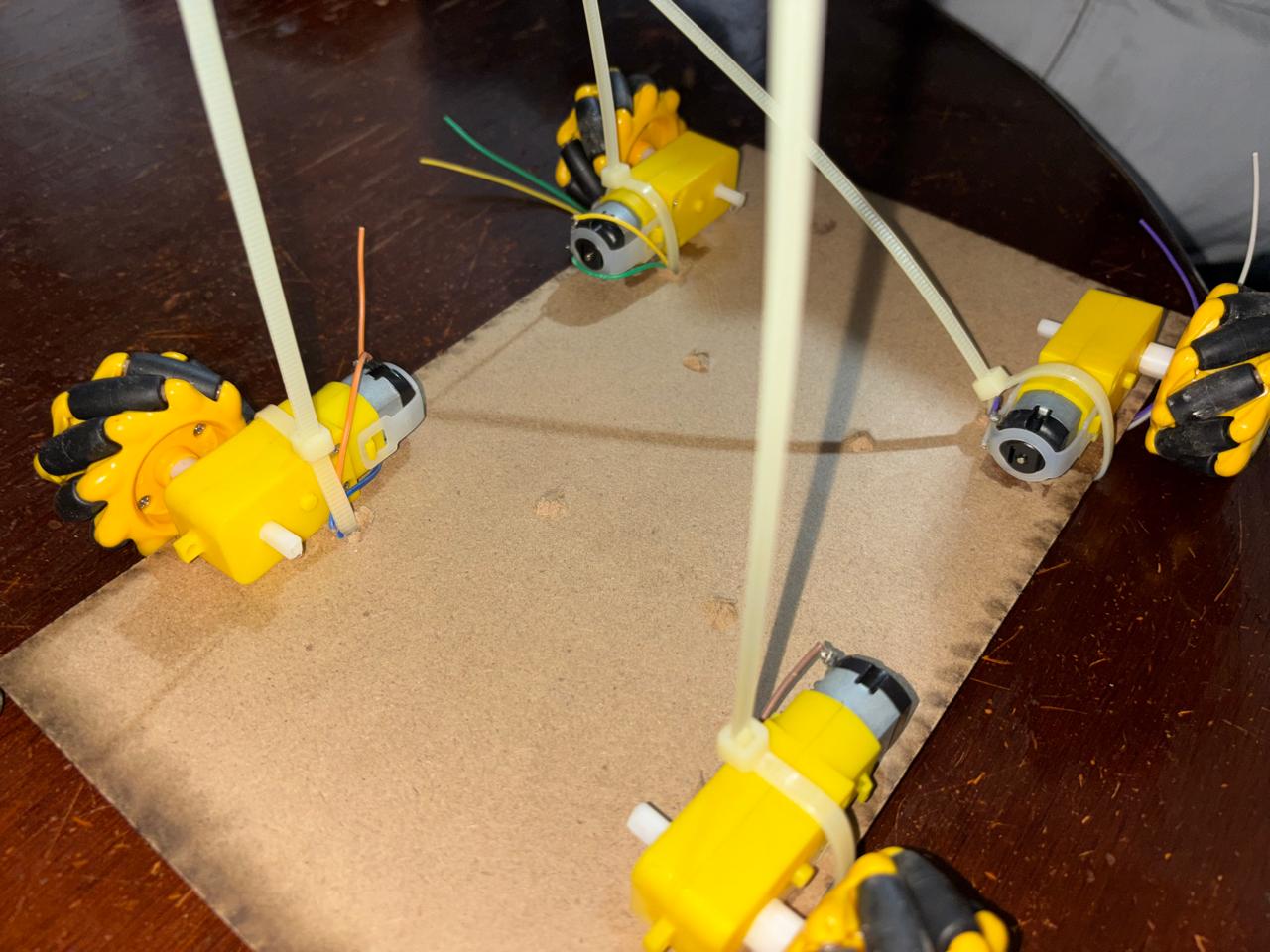
Finally, I assembled the external structure and permanently secured the motors in place. Screws were used to fasten each component, improving mechanical stability and ensuring reliable operation during movement.
How Was the Vehicle Secured?
To secure the vehicle’s components, such as the motors and electronic boards, holes were made in the MDF base. In this way, zip ties were placed around the motors to ensure that they remained completely secure. In the case of the boards, specifically the motor drivers, spaces were intentionally included in the Altium design to accommodate M4 screws mounted onto the base. This allowed me to continue securing the remaining boards in a similar manner. Likewise, for the connections between boards, I used tape to organize the wires into groups and maintain better control over the connections being made. In this way, I secured the internal structure of the vehicle.
Interface and Application Programming
The original objective for the user interface was to control the robot using an Xbox controller connected through Bluetooth. However, the specific controller available for testing could not be updated to a firmware version compatible with the libraries required for communication with the ESP32 platform.
Because of this limitation, I decided to design and develop a custom digital controller using a XIAO ESP32C6.
This decision was influenced by previous experience acquired during an earlier Fab Academy assignment, where I had already experimented with wireless communication interfaces. Since this type of development is particularly interesting to me, creating a dedicated controller for the omnidirectional robot became an exciting extension of the project.
Considering that the primary objective of the robot was obstacle avoidance, I implemented two different operating modes.
The first mode allows the user to manually control the vehicle through directional commands. In this configuration, the robot behaves as a conventional remote-controlled platform.
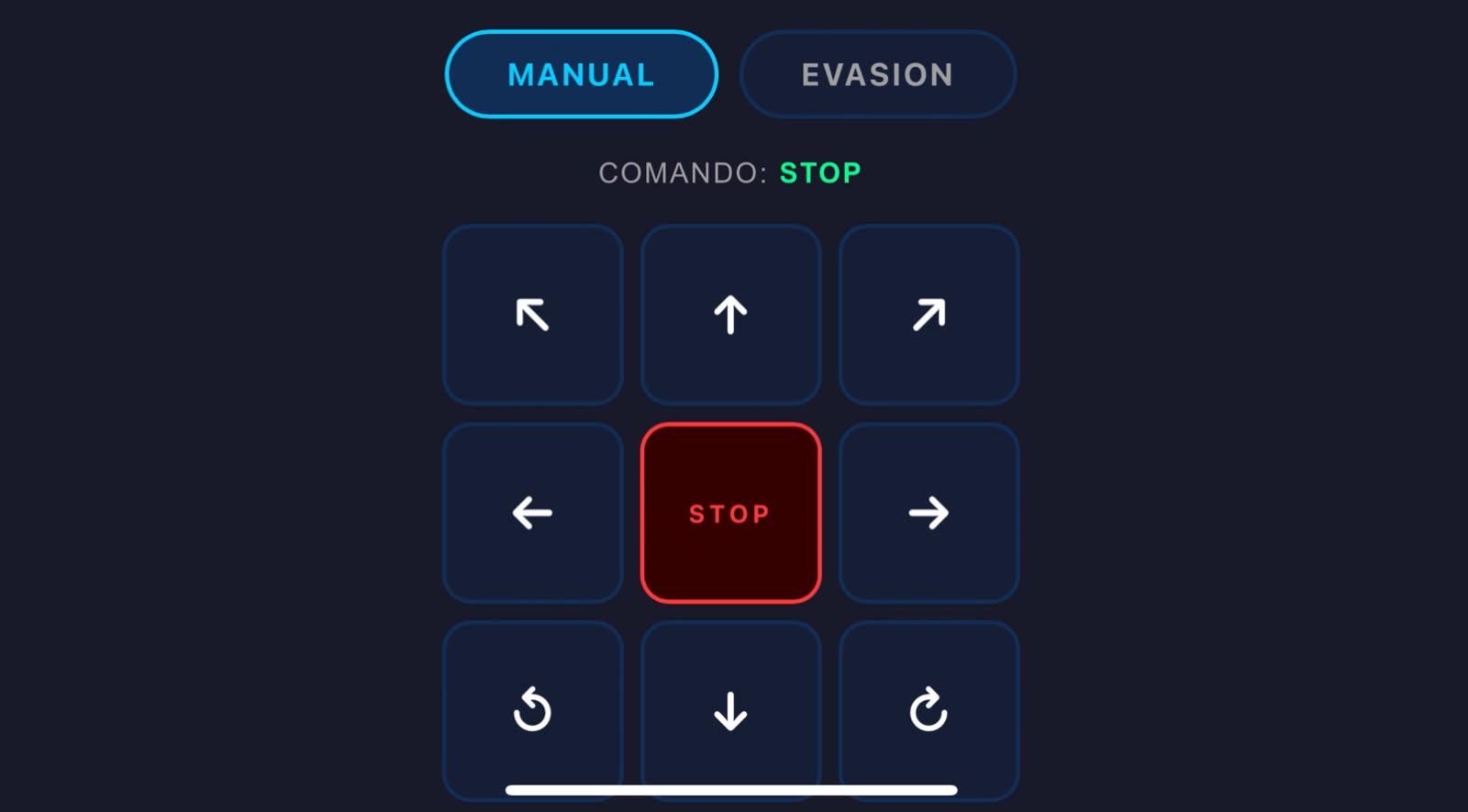
The second mode enables autonomous obstacle avoidance. When activated, manual control is automatically disabled and the robot takes control of its own navigation by using data acquired from the distance sensors to avoid collisions.
The first stage of development consisted of creating the graphical controller interface without integrating any functional logic. This allowed me to verify the layout and communication structure independently from the vehicle control algorithms.
Here is the link for the programming of the html in the XIAO ESP32C6 .zip
Once the interface was operating correctly, I used artificial intelligence as a development support tool. Rather than generating the project from scratch, AI was employed to help organize the codebase and ensure that previously implemented movement functions remained intact while integrating new features.
Using Claude, I created a prompt requesting the integration of the different software modules developed throughout the project while preserving functionality, structure, and readability. The resulting implementation was the following:
"I am carrying out an omnidirectional robot project. I use two microcontrollers. The first one is a XIAO ESP32C6 that creates a web interface where a controller is generated to operate the omnidirectional robot. It also reads data from VL53L0X sensors and transmits these instructions through UART communication to my second microcontroller, a XIAO RP2350. I have the following codes. I need you to integrate the ESP32C6 web interface code with the instructions that it previously had so that they are consistent with each other. Likewise, I would like you to review and correct (if necessary) the XIAO RP2350 code so that it matches the information being sent from the ESP32."
Of course, the codes explained previously were copied and pasted.
This was the final result:.zip