Week 12: Mechanical Design - Machine Design
This week focused on the mechanical and machine design of a CNC sand plotter, emphasizing space optimization, motion systems, and component integration.
Before starting
Mechanical Design is the process of conceiving, planning, and developing physical systems, focusing on the shape, structure, materials, and functionality of components. It involves defining aspects such as dimensions, tolerances, mechanisms, and how individual parts interact to fulfill a specific purpose.On the other hand, Machine Design is a more applied and functional extension of mechanical design, where previously designed components are integrated into a complete system capable of performing a task. It includes the selection of actuators, transmission systems, control, automation, and how the machine will operate under real conditions.
The main difference between them is that Mechanical Design focuses on the design of individual parts and mechanisms (component level), while Machine Design focuses on integrating those elements into a complete machine (system level), also considering its operation, efficiency, and automation.
Mechanical Design
On this occasion, I was responsible for designing the machine’s parts, which can be summarized as follows:- Two corner pieces that house the motors and connect the structural profiles
- Two corner pieces where the lead screws and aluminum guides are mounted
- Two X-axis carriages that must move simultaneously; one houses the Y-axis motor, while the other supports the lead screw and aluminum guide
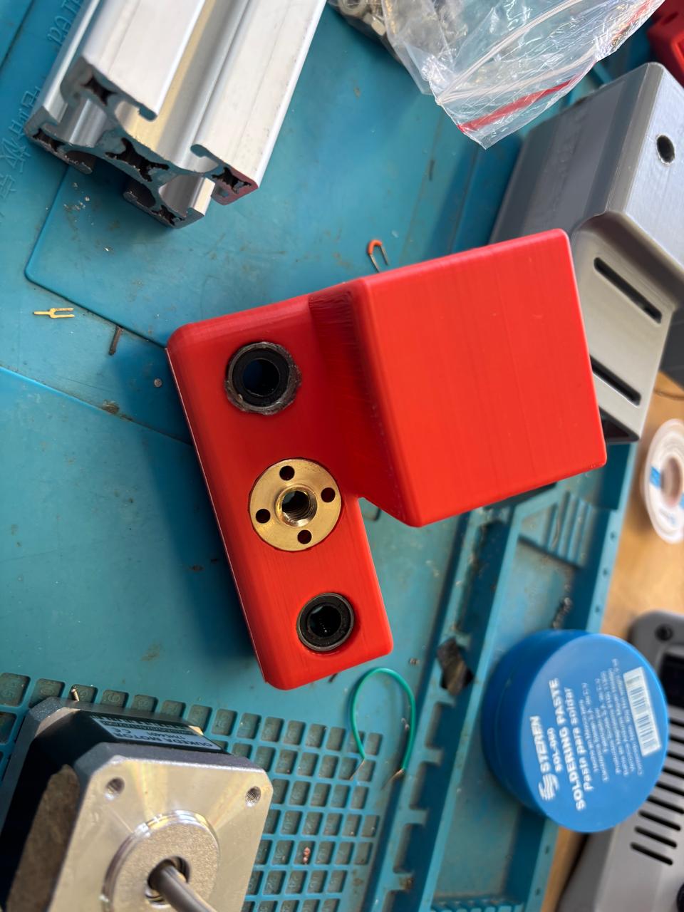
- The carriage that holds the magnet and moves along the Y-axis
- Four brackets that clamp onto the profiles and secure the machine to the base structure
Afterward, this work was integrated with the other phases of the project, which can be found documented on the group’s page.
Planning
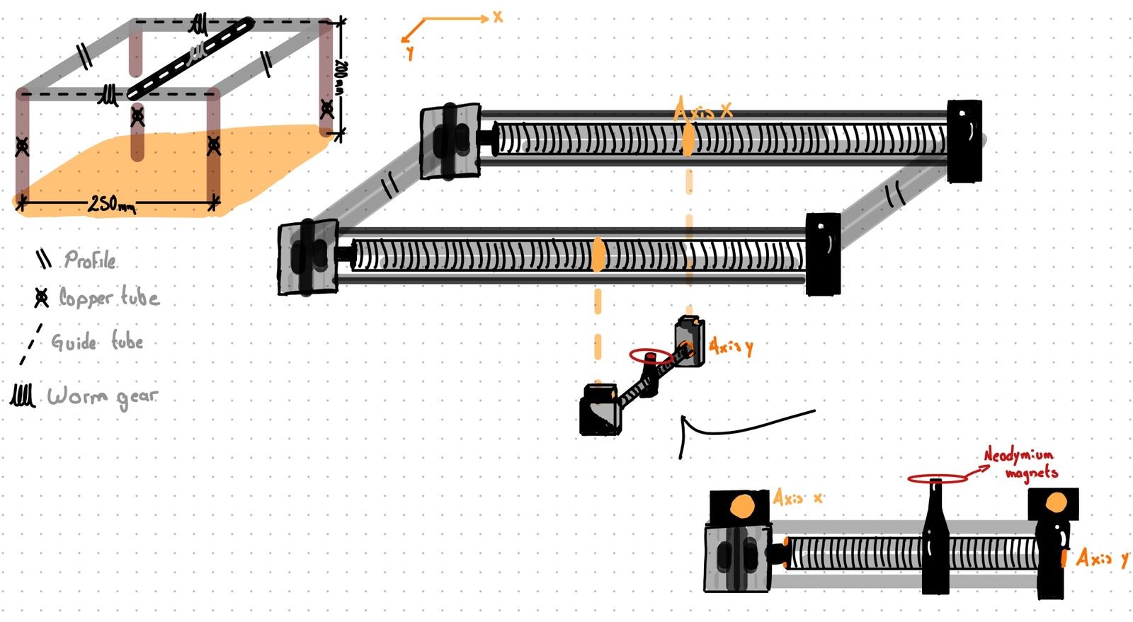
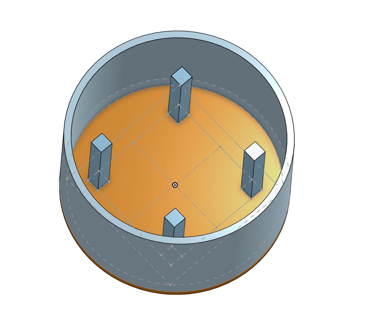
Following the design and plans of the CNC sand plotter, the goal is to achieve the greatest possible space efficiency. To accomplish this, the corners of the structural profiles are used to mount the motors, optimizing the available volume and keeping the system compact.
A carriage is placed to move along the X-axis, while a second carriage moves between the two rails, forming the Y-axis. This configuration allows for coordinated two-dimensional motion while maintaining stability and precision.
A carriage is placed to move along the X-axis, while a second carriage moves between the two rails, forming the Y-axis. This configuration allows for coordinated two-dimensional motion while maintaining stability and precision.
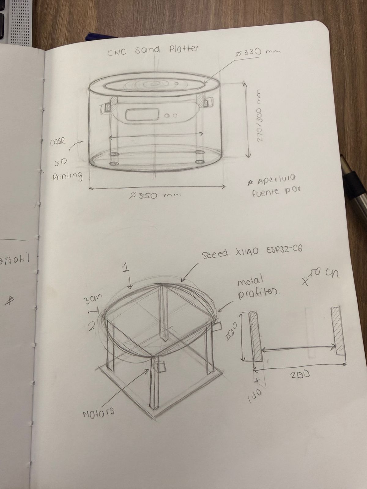
Since the space that the mechanism can occupy is limited by the enclosure, its dimensions must be carefully planned. To ensure accuracy, a base with exact dimensions is first modeled as a reference for the overall design.
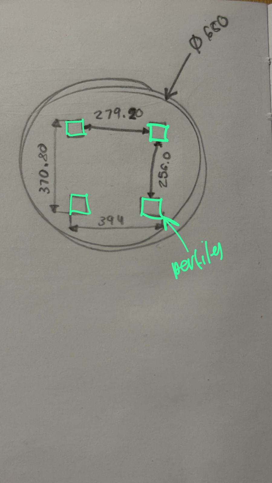 After performing a series of calculations and adjustments, considering component placement, clearances, and motion ranges.
The base is defined as a rectangle of approximately 387 × 396 mm. This reference geometry helps guide the positioning of structural profiles, motors, and linear motion systems, ensuring that all elements fit properly within the available space while maintaining functionality and efficiency.
The base is defined as a rectangle of approximately 387 × 396 mm. This reference geometry helps guide the positioning of structural profiles, motors, and linear motion systems, ensuring that all elements fit properly within the available space while maintaining functionality and efficiency.
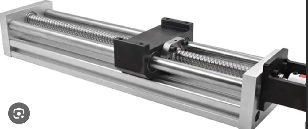
The most critical part of this machine’s design is the motion system driven by the motors, so most of the design revolves around these components.
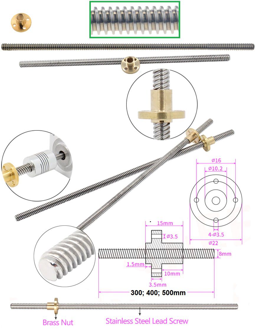
 For the motion system, each motor must be coupled to a lead screw and accompanied by linear guides to enable smooth displacement. Because of this, the design must account for three main clearances: two for the linear guides and one for the central motor shaft. This spatial arrangement is essential to guarantee proper alignment and avoid mechanical interference.
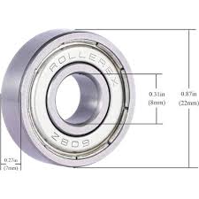
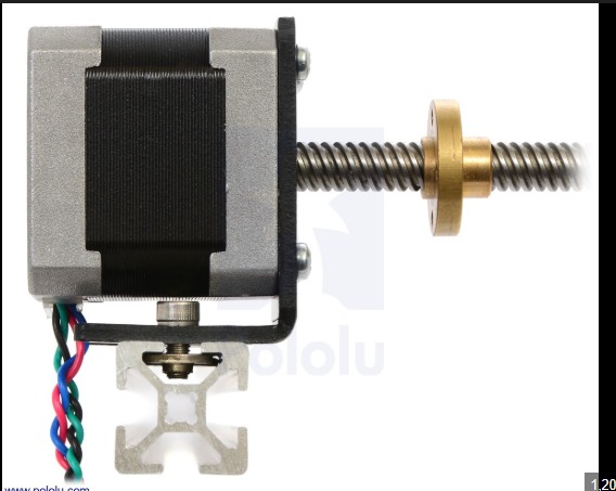 Similarly, the parts that receive these components are designed with matching geometry. They include the same two for the guides, while the lead screw is supported by a bearing. Since the bearing has its own dimensions and mounting requirements, sufficient space must be allocated to ensure proper fit and rotation without friction issues.
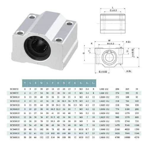
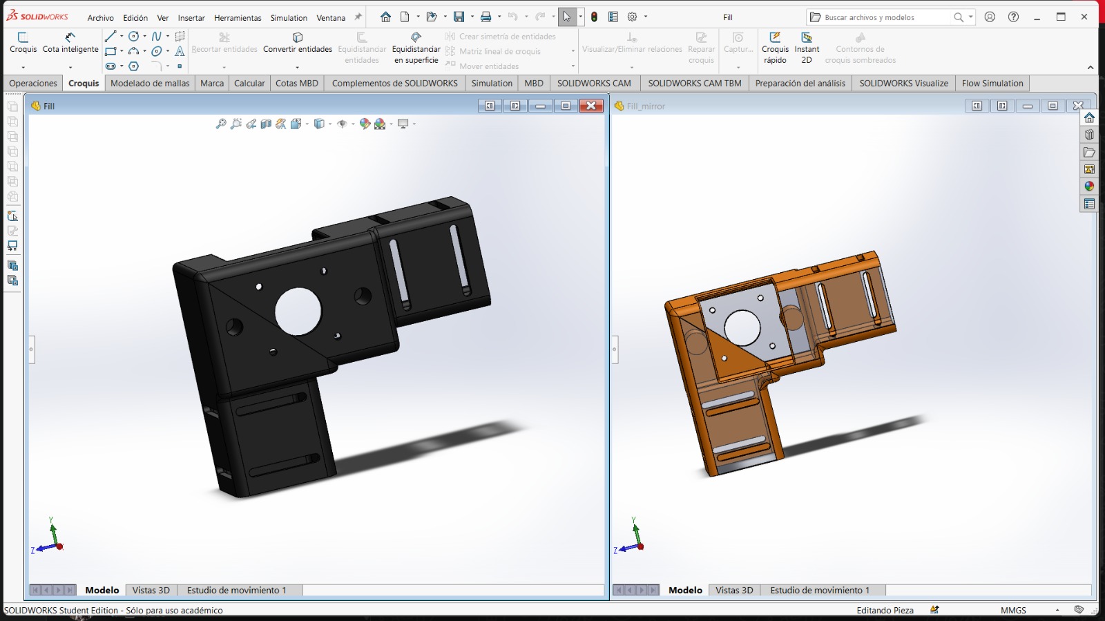
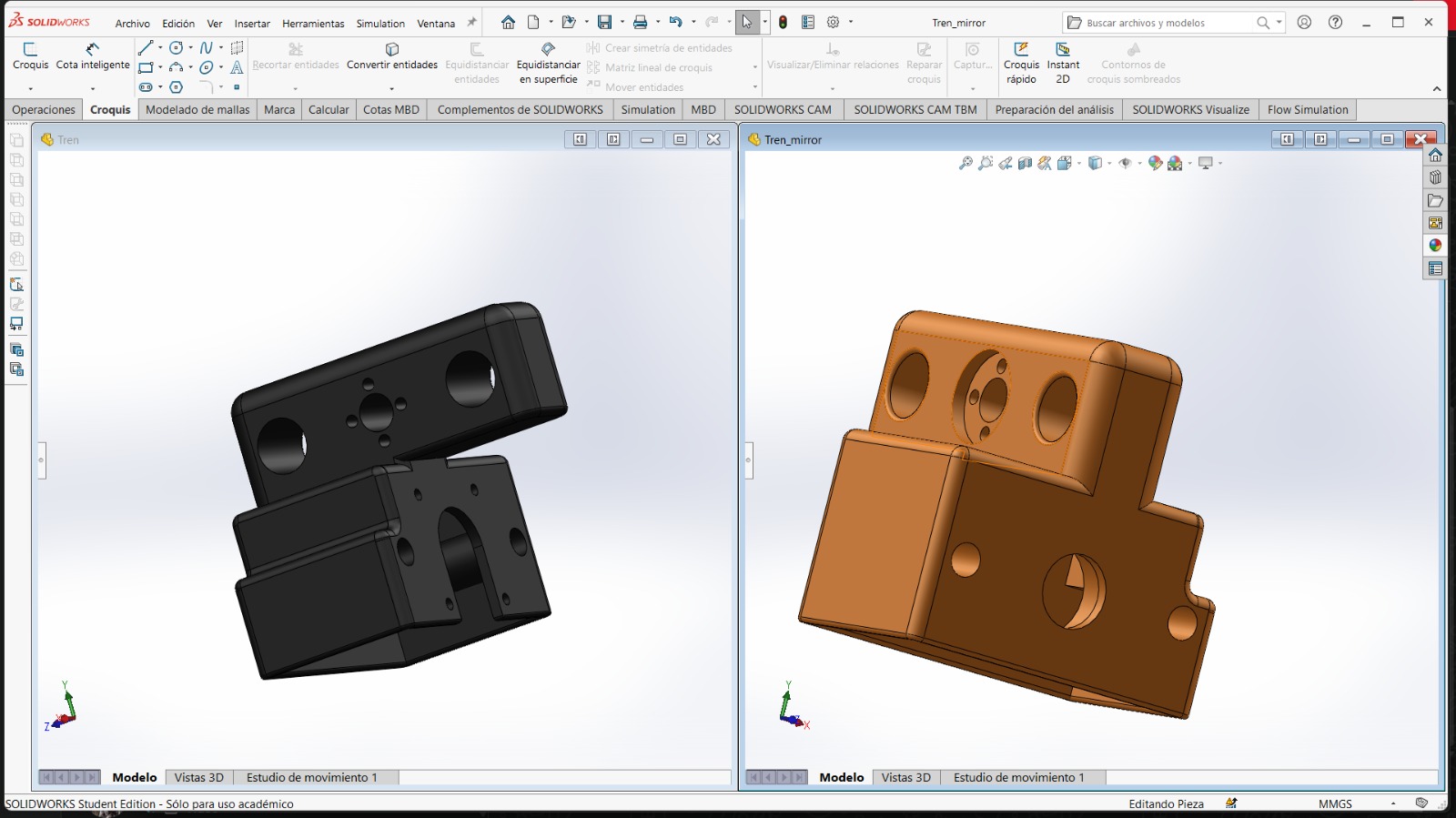
Finally, the components that move along the X-axis are designed in two parts. This is because they must engage with the lead screws on both sides while also incorporating the previously described structure for the Y-axis system. These moving parts include two holes for slim bearings, which help maintain alignment and reduce friction, as well as a central hole for a component that follows the path of the lead screw, enabling precise linear motion.
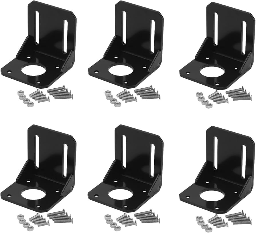
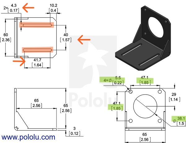
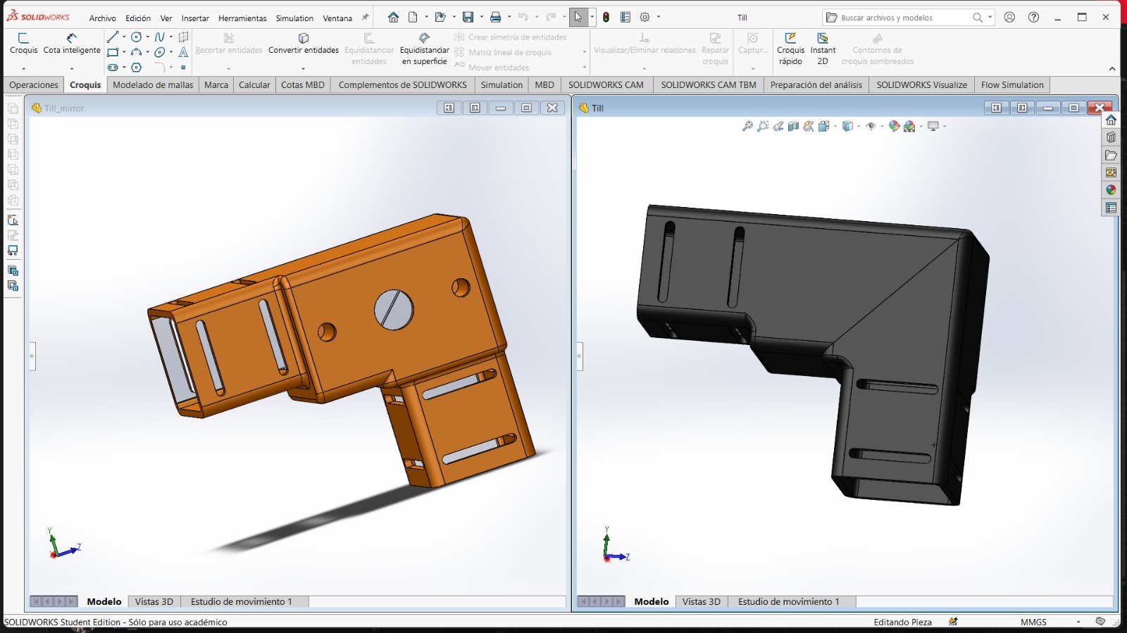
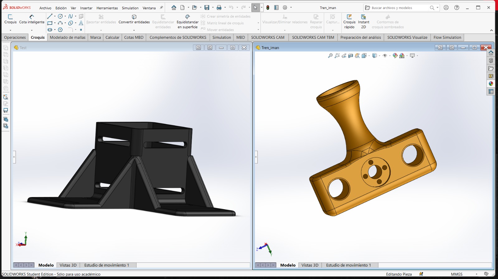
To begin with, the motors are supported by L-shaped brackets. These brackets have a front plate that allows the motor to be mounted using four screws, while leaving space for the central shaft opening. In addition, they include side guides that keep the bracket firmly attached to the structural profiles using a nut-based fastening system, ensuring proper alignment and rigidity.
Finally, the components that move along the X-axis are designed in two parts. This is because they must engage with the lead screws on both sides while also incorporating the previously described structure for the Y-axis system. These moving parts include two holes for slim bearings, which help maintain alignment and reduce friction, as well as a central hole for a component that follows the path of the lead screw, enabling precise linear motion.
With all of this in mind, there is one final aspect to consider: the dimensions of the parts.
Since most of the components were purchased, we have access to their technical drawings and specifications. This allows us to extract accurate measurements directly from reliable sources, minimizing the risk of design errors.
By working with these predefined dimensions, we can ensure proper fitting between components, maintain correct tolerances, and avoid issues during assembly.
Additionally, this approach speeds up the design process, as it reduces the need for trial-and-error adjustments and helps guarantee compatibility between mechanical elements such as motors, bearings, lead screws, and guides.
Design
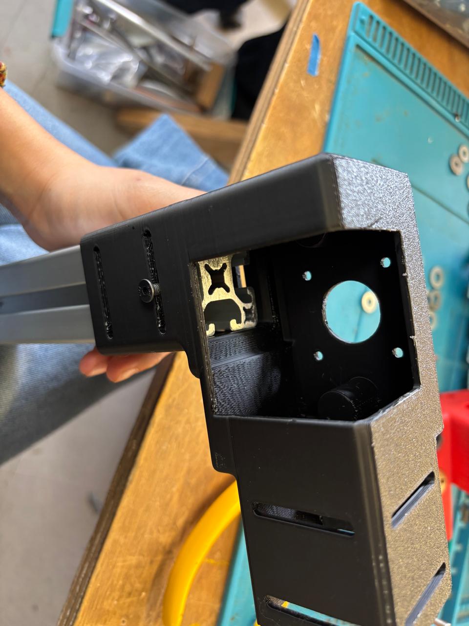
Following the component drawings and considering that 40 mm profiles will be used, the parts were designed with a central clearance intended to house the components and allow easy access for installation and maintenance.
The parts supported by the profiles are designed as follows:
- They include mounting features that match the profile geometry, ensuring a secure and aligned fit
- Clearance zones are incorporated to avoid interference with moving elements such as lead screws and guides
- Fastening points are strategically placed to simplify assembly while maintaining structural rigidity
Following the same design approach, the carriages (or “trains”) are developed with their respective functionalities, including provisions for motion along the axes, bearing placement, and coupling with the lead screws. Additionally, brackets are designed to connect the profiles to the base structure, which was developed by another part of the team, ensuring full integration of the mechanical system.
Results
Assembly
Download files
For download 3D and others files, just click on the dancing shrimp.