WEEK 12

TASK
MONDAY
WEDNESDAY
FRIDAY
MONDAY

✦ Introduction

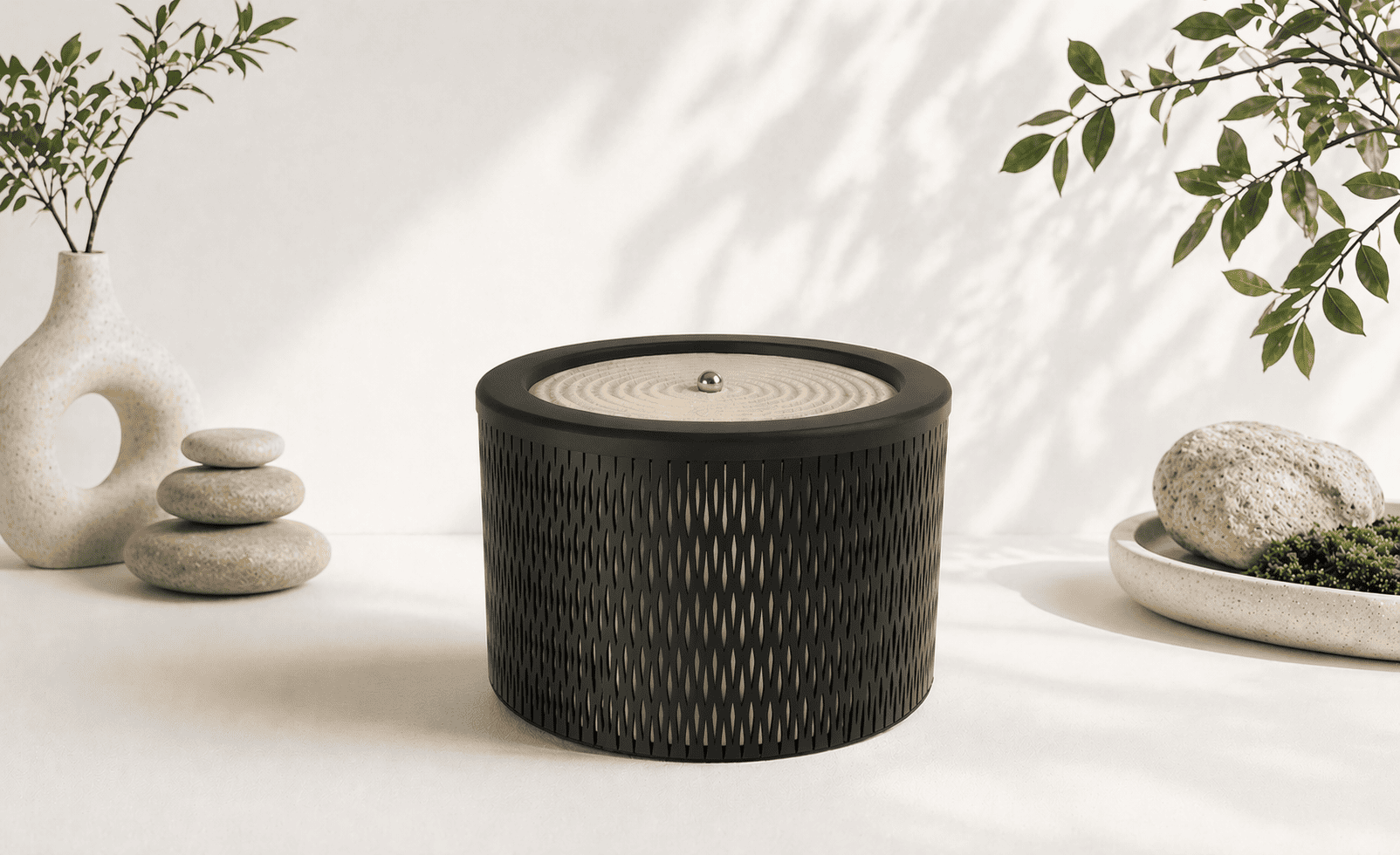
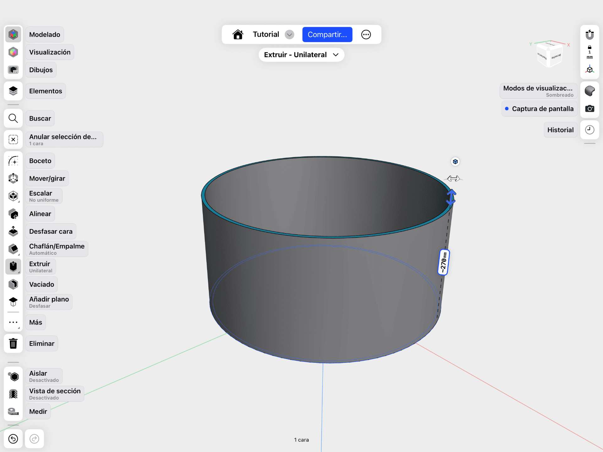
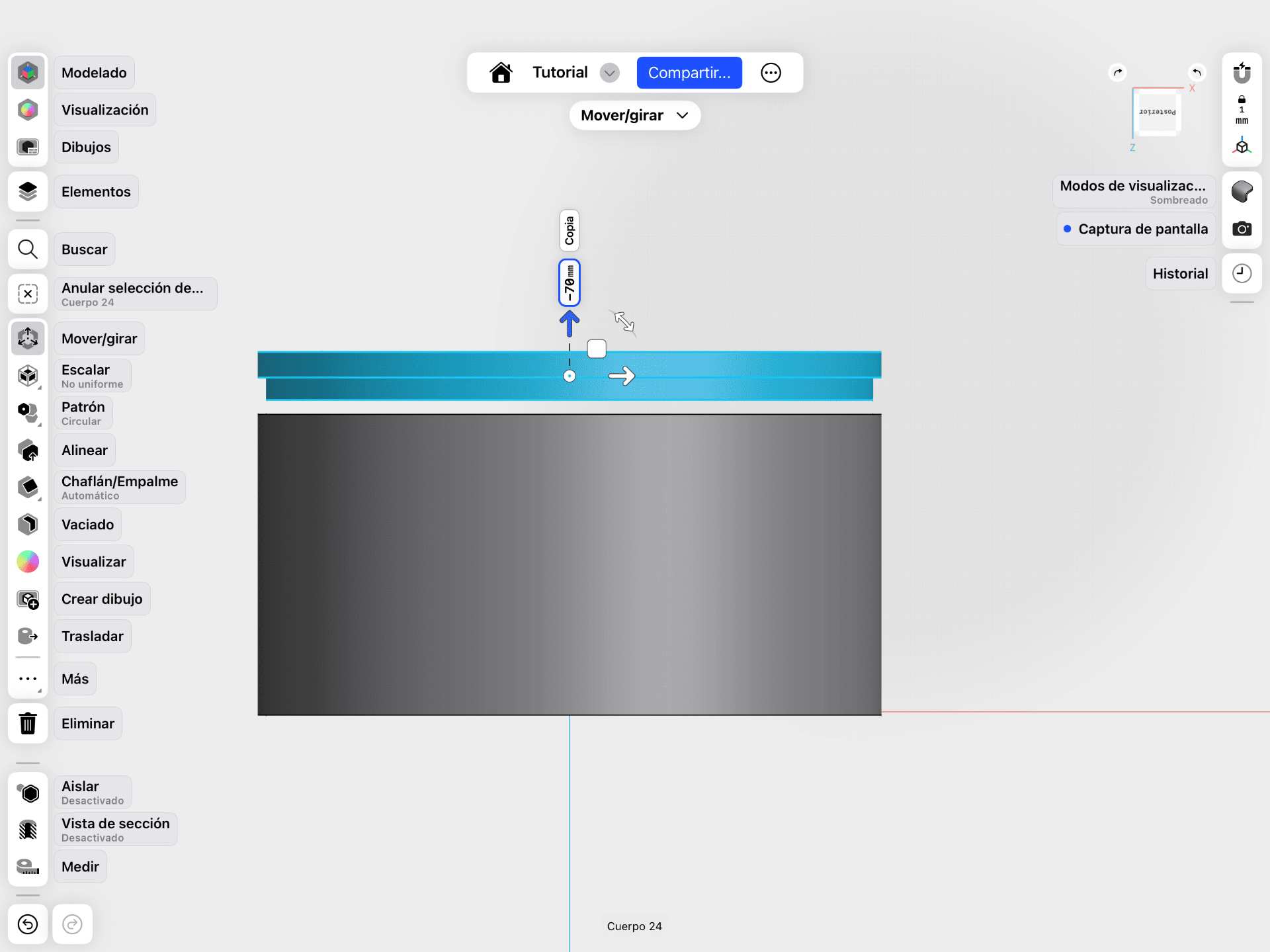
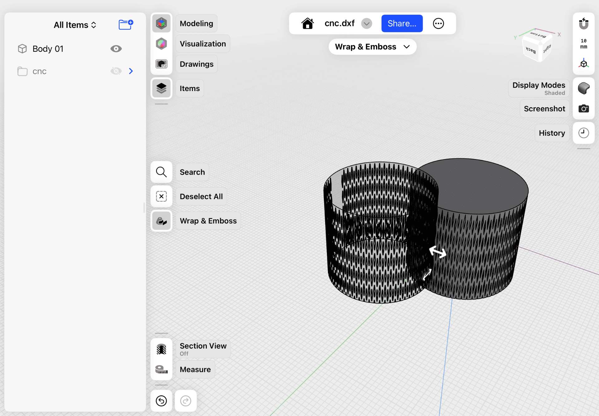
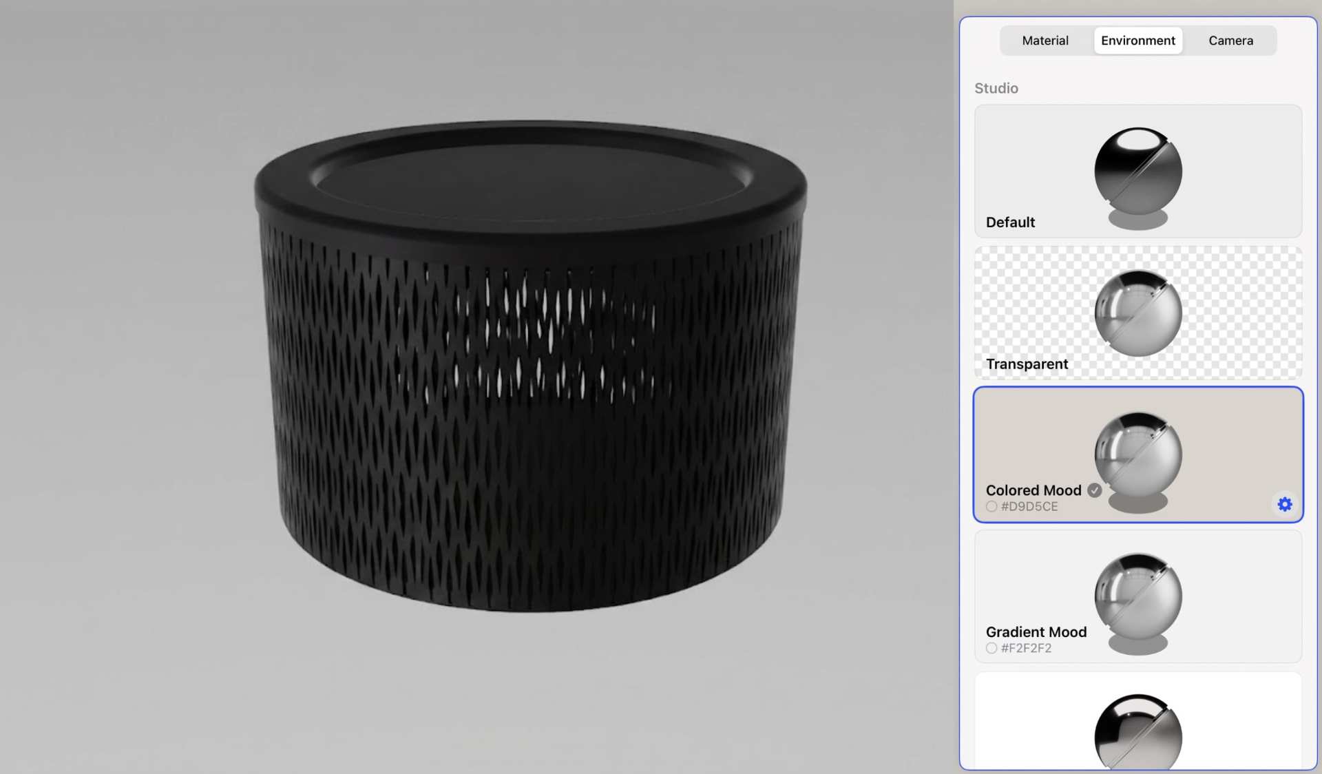
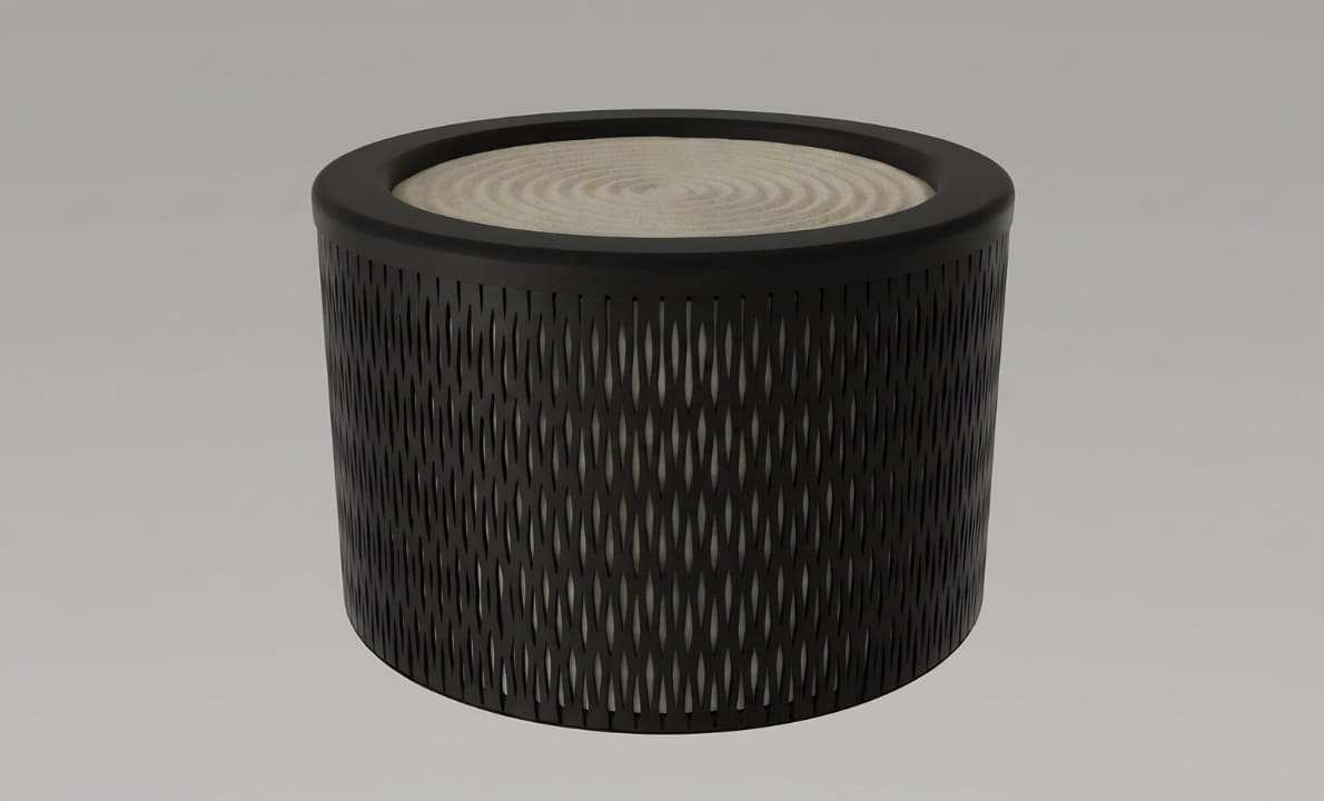
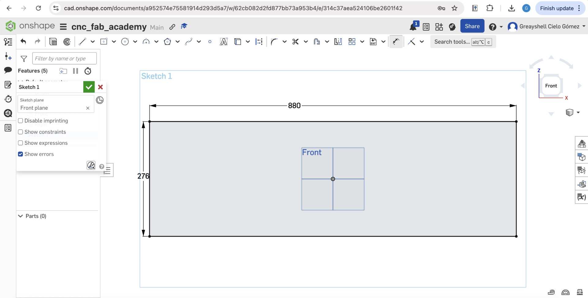
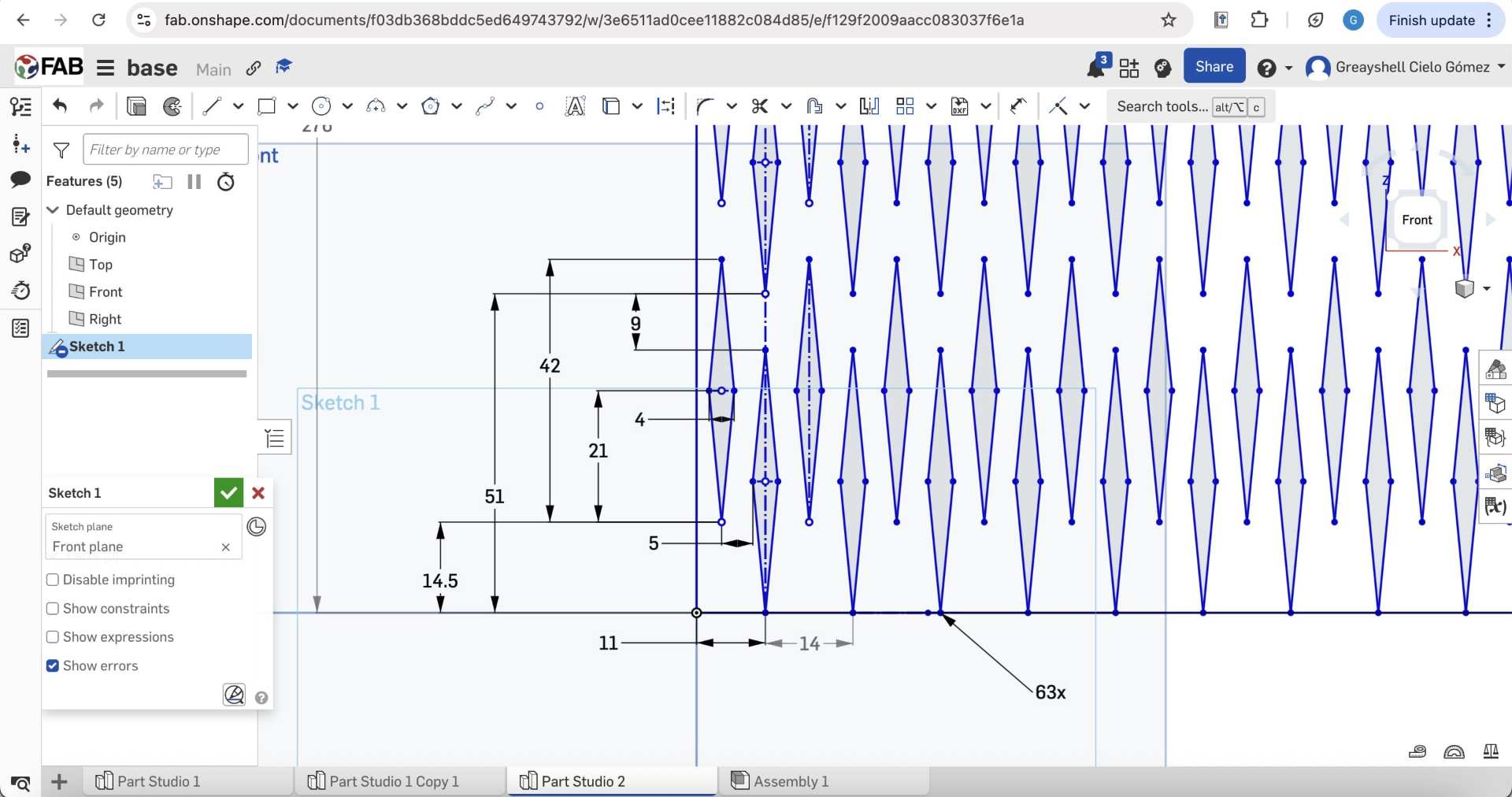
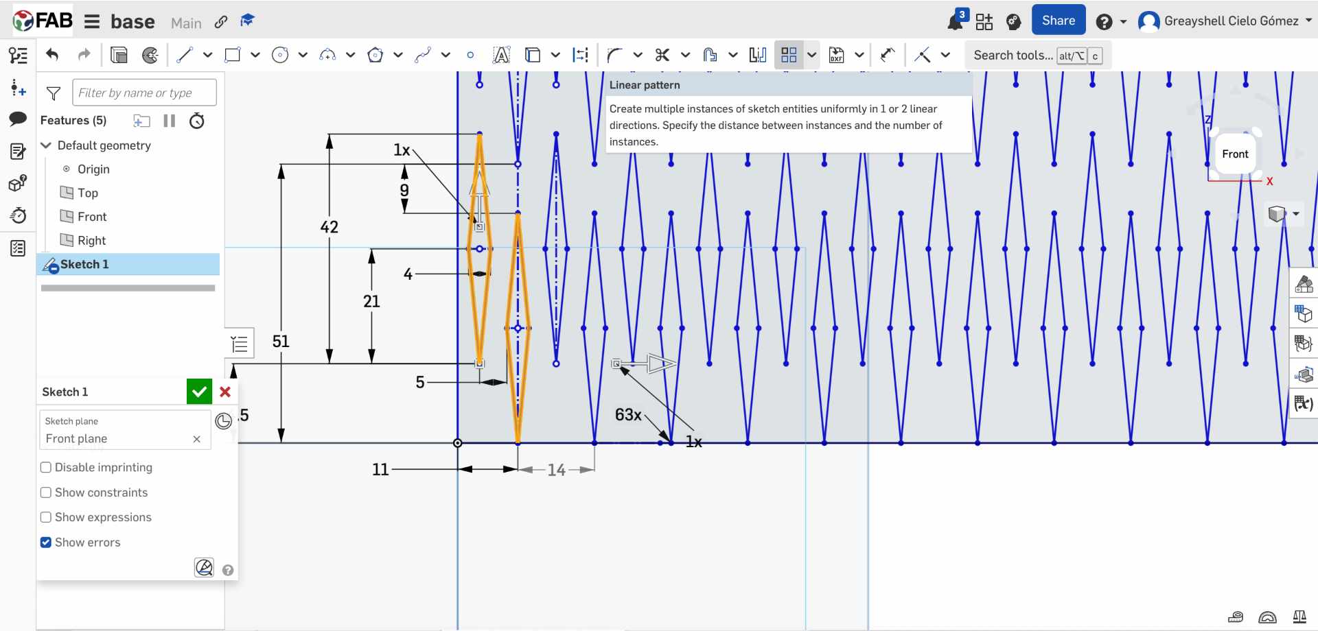
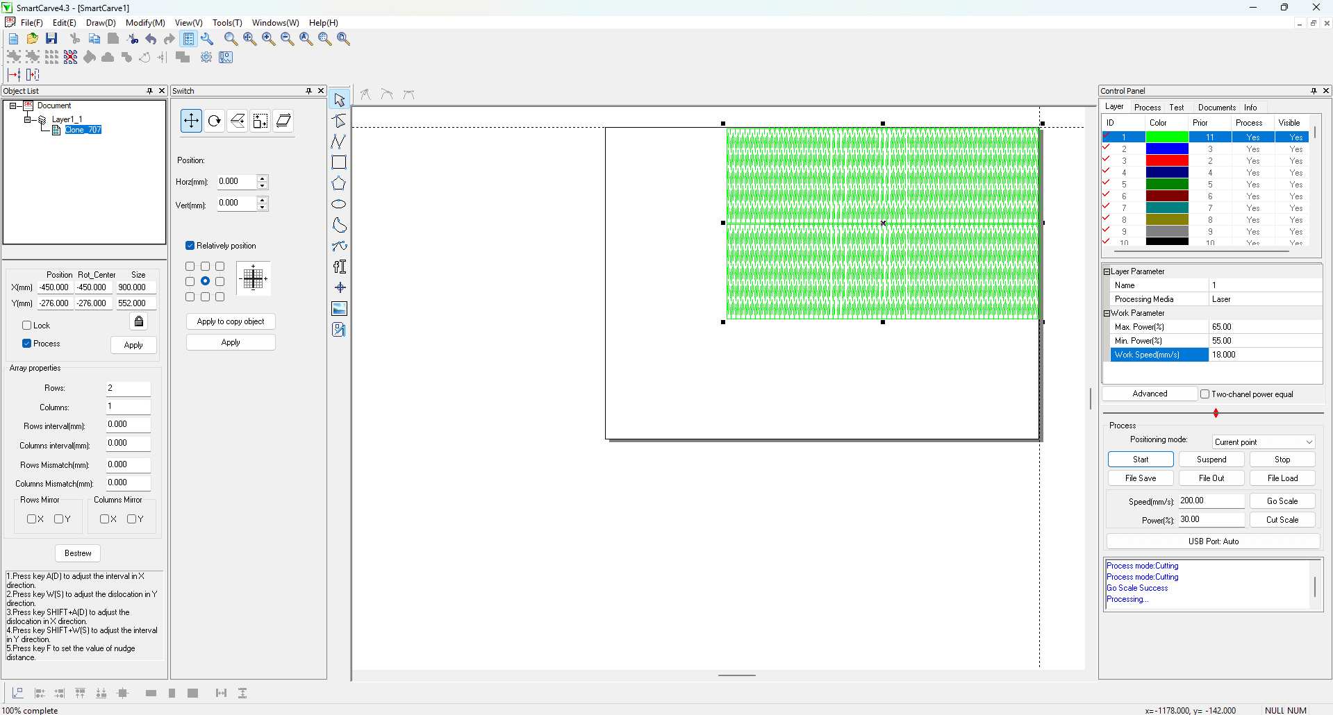
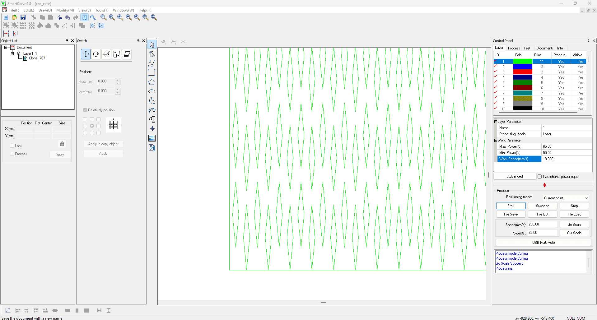
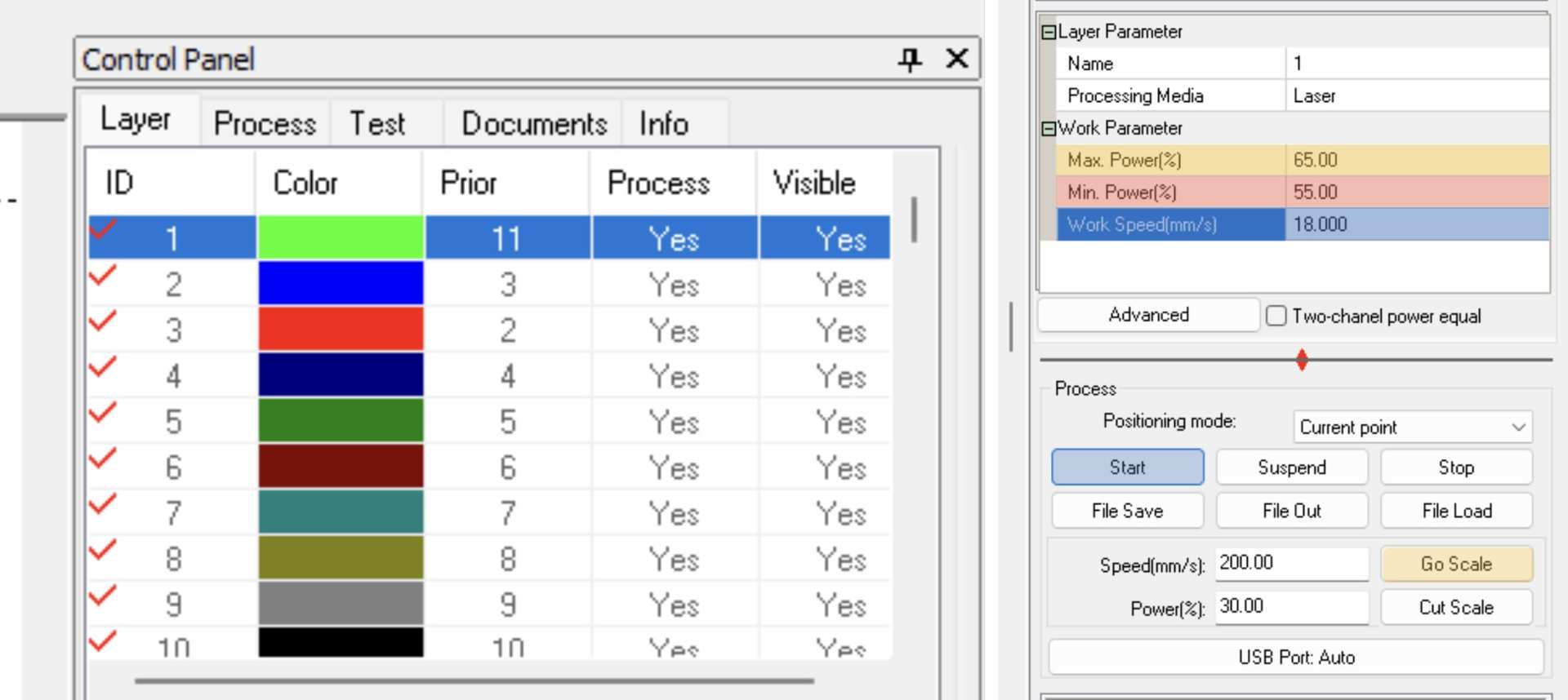
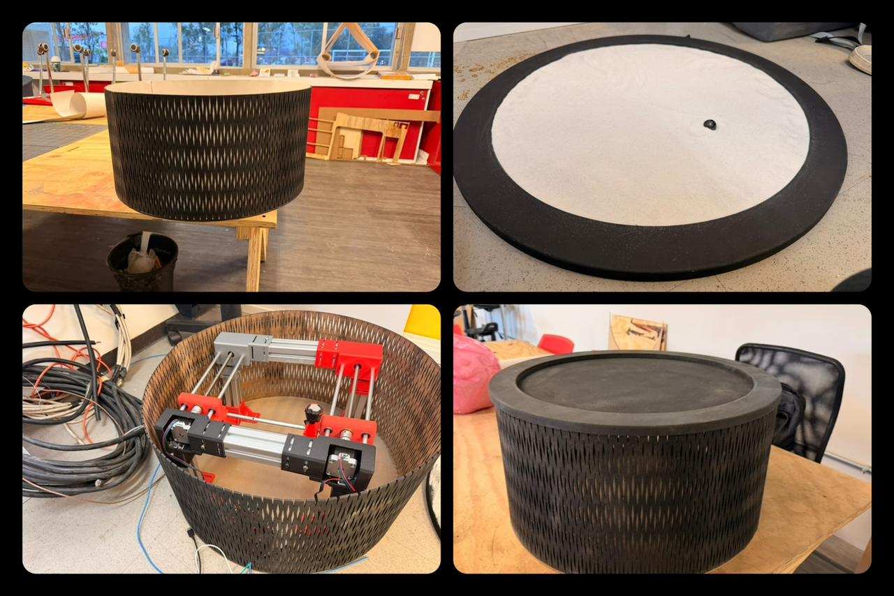
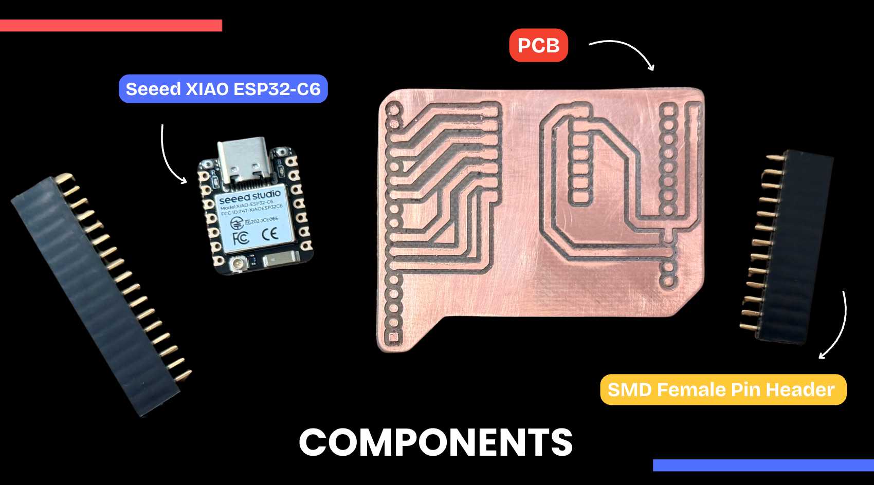
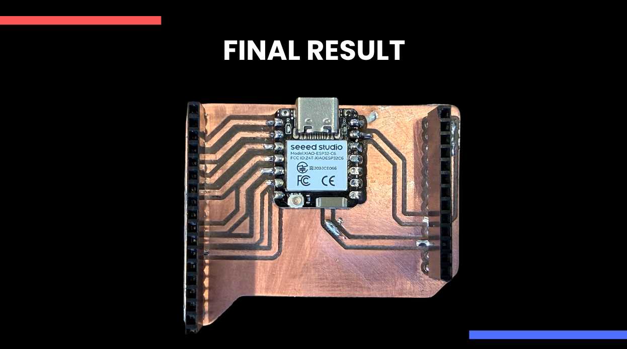
For this week, our team developed a CNC-based zen garden machine that draws patterns in sand by moving a magnet beneath the surface using a Cartesian XY system. For this, a custom web interface converts PNG images into G-code and sends it wirelessly to an ESP32-C6, enabling real-time control of the machine. This is our group page: Group Assignment.

✦ Individual Contribution

My contribution focused on the design and fabrication of the external enclosure, as well as the development of a custom ESP32-C6 control board. This involved integrating both the structural and electronic aspects of the system to ensure proper housing, functionality, and overall coherence of the project and user experience.

Pinout Diagram

✦ Design & Visualization

The enclosure was designed as a protective and structural housing for the CNC sand plotter, maintaining a clean and minimal appearance while containing all internal components. It was first conceptualized in Shapr3D, where the cylindrical geometry was defined to accommodate the internal XY mechanism and ensure overall stability.

✦ Shaper3D

Used for initial conceptual design and visualization, allowing exploration of form, proportions, and overall aesthetics.

✦ OnShape

Used for precise CAD modeling, defining all components and preparing geometries for fabrication.

✦ LASER CUTTING STEPS

Process used to fabricate all components from 3 mm MDF, ensuring accurate cuts and enabling the flexible pattern.

✦ ASSEMBLY PROCESS

between the external shell and the internal mechanism.

01. SURFACE PREPARATION

Once the pieces were cut, they were lightly sanded to remove burn marks from the laser. For this, use sandpaper and a Dremel tool to make the process easier.

02. GLUING COMPONENTS

The rings and top cover were assembled using white glue, applying pressure to ensure proper alignment and prevent movement during drying.

Pinout Diagram

03. SPRAY PAINTING

After assembly, two coats of matte black spray paint were applied to improve the final finish.

Pinout Diagram

04. ATTACHING THE FLEXIBLE STRIP

The flexible strip was gradually glued along the outer edge of the base, ensuring that the walls remained straight during the process.

Pinout Diagram

05. INTERNAL LINING

An inner layer of off-white cardstock was added to the interior walls using hot glue, improving both structure and appearance.I also used the Dremel to make a hole for the CNC cables to pass through.

Pinout Diagram

06. FINAL RESULT

Final touch-ups were made with black paint, resulting in the completed enclosure.

Pinout Diagram

✦ ELECTRONICS PRODUCTION

Likewise, I was helping in other parts of the project, such as soldering our Seeed XIAO ESP32-C6 board, which would be connected to a driver and make our CNC machine work via Wi-Fi.

01. ORGANIZE COMPONENTS

All components were organized and positioned on the PCB before soldering. The soldering iron was set to an appropriate temperature (~270 °C), and flux was prepared to improve solder flow and adhesion. Also place tape on the back of the Xiao to prevent a short circuit.

Pinout Diagram

02. SOLDERING PROCESS

SMD components were soldered by first fixing one pad to hold the part in place, followed by soldering the remaining pads. Care was taken to ensure proper alignment and avoid solder bridges.

03. FINAL RESULT

All components were organized and positioned on the PCB before soldering. The soldering iron was set to an appropriate temperature (~270 °C), and flux was prepared to improve solder flow and adhesion. Also place tape on the back of the Xiao to prevent a short circuit.

Pinout Diagram

06. VIDEO OF OUR CNC

Final touch-ups were made with black paint, resulting in the completed enclosure.

✦ Download Here!

In this section, you can find the downloadable source files developed during this week.

ZIP

ONSHAPE DXF

Download File