Week 10. Output devices
Summary
This week we focused on learning how to use output devices, the different type of devices that exist and how to send each data through our microcontroller. For this week I used servomotors and my pcb from week 8.
Group assignment
Here is the group assignment to check more information about the topic embedded programming.
1. Basic concepts
1.1 What is a servomotor?
Cctuating device that allows highly precise control of the angular position, speed, and acceleration of an object through the PWM.
1.1.1 Why are they useful?
They are useful when precise control of the movement is required like in the following areas:
- Robotics: Joints allow a robotic arm or the legs of a hexapod to move with millimeter precision.
- RC systems: Moving the ailerons of scale model airplanes, the rudder of ships, or the steering of RC cars.
- Industrial Automation: Moving conveyor belts to exact positions or managing robotic arms on assembly lines.
- Camera Systems: In gimbals, they keep the camera level while moving.
1.1.2 What is PWM?
Pulse Width Modulation consists of varying the duration that an electrical signal remains in the "high" (on) state within a constant cycle to transmit a specific instruction.
1.1.2.1 How it works?
It is based on the time the signal remains in a high state within a constant period. For most servos, this period is 20ms (equivalent to a frequency of 50Hz). What defines the motor's position is not the total period, but the pulse width Duty Cycle within those 20ms. Typically, a 1ms pulse positions the servo at 0°, while a 2ms pulse moves it to 180°.
The mapping process involves translating the desired range of motion (0° to 180°) to the bit resolution of our microcontroller, ensuring that the generated pulse always falls within the time limits that the servo's internal circuitry can interpret.
1.1.3 What is Duty Cycle?
Is the ratio between the time the signal remains in a high or on state and the total time of a complete cycle, or period. If we imagine the period as a complete lap on a racetrack, the duty cycle would be the section of that track where the driver decides to accelerate fully.
Mathematically, the period is the inverse of the frequency T = 1/f; for our servos at 50Hz, this total time is 20ms. In servo motor control, the duty cycle is a small fraction of the period. For example, a 1.5ms pulse within a 20ms cycle represents a duty cycle of 7.5%. It is this exact percentage that the servo's internal circuitry interprets to position the shaft, allowing precise control through variations in time rather than voltage.
1.1.4 What is mapping
Linear interpolation is a technique that transforms an input range into an output range while preserving the ratio. In embedded systems programming, we use it to convert a variable we easily understand (such as the 0° to 180° rotation of a robot leg) into the specific values that the microcontroller hardware needs to process (such as 500 to 2500 microseconds). In ersume is to translate values from a sacle to another.
The mapping depends on the resolution or number of bits a microcontroller has; for example, an 8-bit timer counts up to 255, while a 16-bit timer counts up to 65,535. With this we can obtain the time per bit of a microcontroller.
1.1.4.1 How to do the mapping?
- Consult the servo datasheet (usually 1ms to 2ms).
- Know the PWM resolution of your microcontroller (8, 12, or 16 bits).
- Calculate the ratio with respect to the 20ms period.
1.1.5 How we can apply this?
Mathematically or theoretically.
1. TEMPORAL RESOLUTION (TIME PER BIT)
First, we determine how much time each unit of our resolution represents (example for 16 bits):
2. CONVERSION TO MACHINE VALUES
We calculate the pulse limits based on the time per bit obtained:
3. FINAL MAPPING FORMULA
Meanwhile here is an example if we would like to code our mapping values using a Xiao rp2040. First sending exact positions.
                    /**
                    * Angle-to-PWM Mapping
                    * Platform: XIAO RP2040 (16-bit Resolution)
                    * How to translate degrees (0-180) into precise PWM pulses.
                    */

                    // 16-bit PWM constants for 50Hz (20ms period)
                    // Calculated as: (Pulse_ms / 20ms) * 65535
                    const int PULSE_MIN = 3277;    // 1.0ms = 0 degrees
                    const int PULSE_MAX = 6554;    // 2.0ms = 180 degrees

                    const int SERVO_PIN = D0;

                    void setup() {
                    analogWriteResolution(16);   // Set PWM to 16-bit resolution
                    analogWriteFreq(50);         // Set frequency to 50Hz (Standard for servos)
                    pinMode(SERVO_PIN, OUTPUT);
                    }

                    void loop() {
                    // Move to 3 key positions to demonstrate accuracy
                    moveToAngle(0);
                    delay(1000);

                    moveToAngle(90);
                    delay(1000);

                    moveToAngle(180);
                    delay(1000);
                    }

                    /**
                    * Function: moveToAngle
                    * Translates a degree value into a 16-bit Duty Cycle value.
                    * Angle from 0 to 180.
                    */
                    void moveToAngle(int angle) {
                    // Safety: Constrain the angle to the physical limits of the servo
                    angle = constrain(angle, 0, 180);

                    // Mapping formula: map(value, fromLow, fromHigh, toLow, toHigh)
                    int pwmValue = map(angle, 0, 180, PULSE_MIN, PULSE_MAX);

                    // Send the calculated Duty Cycle to the pin
                    analogWrite(SERVO_PIN, pwmValue);
                    }
Now if we want to move the servomotors with potentiometers.
                    /**
                    * Real-time Duty Cycle Modulation
                    * Platform: XIAO RP2040 (12-bit ADC to 16-bit PWM)
                    * Manual control of a servo using a potentiometer.
                    */

                    // 16-bit PWM constants for 50Hz
                    const int PULSE_MIN = 3277;    // 1.0ms
                    const int PULSE_MAX = 6554;    // 2.0ms

                    const int POT_PIN   = A0;      // Potentiometer input
                    const int SERVO_PIN = D0;      // Servo output

                    void setup() {
                    analogReadResolution(12);    // Set ADC to 12-bit (0-4095 range)
                    analogWriteResolution(16);   // Set PWM to 16-bit (0-65535 range)
                    analogWriteFreq(50);         // 50Hz frequency

                    pinMode(SERVO_PIN, OUTPUT);
                    pinMode(POT_PIN, INPUT);
                    }

                    void loop() {
                    // Call the manual control function
                    controlWithPot();

                    // Small delay to prevent signal noise/jitter
                    delay(15);
                    }

                    /**
                    * Function: controlWithPot
                    * Reads the raw analog voltage and converts it to a PWM pulse width.
                    */
                    void controlWithPot() {
                    // Read the potentiometer value (0 to 4095)
                    int potValue = analogRead(POT_PIN);

                    // Map the 12-bit ADC range to the 16-bit PWM servo range
                    int pwmValue = map(potValue, 0, 4095, PULSE_MIN, PULSE_MAX);

                    // Update the servo position based on the potentiometer
                    analogWrite(SERVO_PIN, pwmValue);
                    }
2. Library to use
Fortunately nowadays we can use libraries that save us time to not do the maths from the begging but is important to know how to map our values in case our microcontroller or IDE software don't have a library that we can use.
In my case I will use the library Servo.h which is the most common to use in the Arduino IDE. This library is already installed becasue it comes with the core of liraries from Raspberry Pi Pico/RP2040 necessaries to use the xiao so install this library by clicking on the icon with books (libraries), search Raspberry Pi Pico/RP2040 and click on install. Servo.h have the next functions:
| Command | Function |
|---|---|
| attach(pin, min, max) | It connects the software to the hardware. It tells the microcontroller which PWM pin will generate the signal. |
| write(angle) | It receives an integer (0 to 180) and internally performs the mapping formula we saw earlier. It converts that angle into the corresponding pulse width (Duty Cycle). |
| writeMicroseconds(us) | It sends the exact pulse width value in microseconds. Perfect if you want a smoother, cleaner movement. |
| read() | Returns the last angle you requested from the servo. |
| attached() | Returns a boolean value (true or false) indicating whether the servo is correctly configured on a pin. |
| detach() | Stop sending the PWM signal to the pin. |
Here is an example using most of the functions of the Servo.h library.
                    /**
                    * Library: Servo.h
                    * Demonstrates attach, write, writeMicroseconds,
                    * read, attached, and detach functions.
                    */

                    #include <Servo.h<

                    Servo legServo;              // Create the servo object
                    const int SERVO_PIN = D0;    // PWM pin on XIAO RP2040
                    const int LED_PIN = LED_BUILTIN;

                    void setup() {
                    Serial.begin(115200);
                    pinMode(LED_PIN, OUTPUT);

                    // 1. ATTACH: Initialize the servo with specific pulse limits (500us to 2500us)
                    // This helps calibrate the full 180-degree range of the MG90 motors.
                    legServo.attach(SERVO_PIN, 500, 2500);

                    // 2. ATTACHED: Verify if the servo was successfully initialized
                    if (legServo.attached()) {
                        Serial.println("Servo is successfully attached to pin D0.");
                        digitalWrite(LED_PIN, HIGH);
                    }
                    }

                    void loop() {
                    Serial.println("--- Starting Movement Routine ---");

                    // 3. WRITE: Move using standard degrees (0 to 180)
                    Serial.println("Moving to 90 degrees...");
                    legServo.write(90);
                    delay(1000);

                    // 4. READ: Check the last commanded angle
                    int currentAngle = legServo.read();
                    Serial.print("Current logical angle: ");
                    Serial.println(currentAngle);

                    // 5. WRITEMICROSECONDS: Ultra-precise movement for fine tuning
                    // 1500us is center, 1550us is a tiny 4.5 degree shift.
                    Serial.println("Fine-tuning position with microseconds...");
                    legServo.writeMicroseconds(1550);
                    delay(1000);

                    // 6. DETACH: Stop sending PWM signal to save power and prevent jitter
                    // This is vital for your 18-servo hexapod to avoid overheating while idle.
                    Serial.println("Detaching servo to save power...");
                    legServo.detach();

                    // Check status again
                    if (!legServo.attached()) {
                        Serial.println("Servo is now idle (detached).");
                        digitalWrite(LED_PIN, LOW);
                    }

                    delay(3000); // Wait 3 seconds before re-attaching

                    // Re-attach to start the loop again
                    legServo.attach(SERVO_PIN, 500, 2500);
                    }
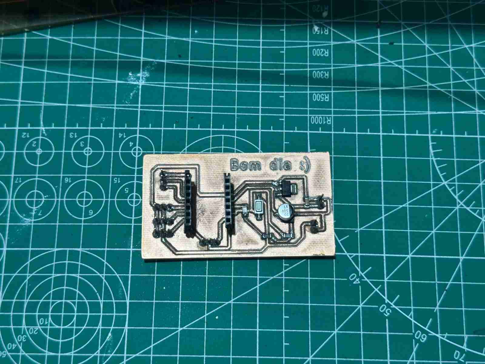
3. Board
For this week I will use the board I made during week 8. or even from the week 9 because in both I put pins to control servomotors.
4. Connections
The pinout of the servomotors is very simple it has 3 colors and in most cases the servomotors comes with cables with this pattern of colors:
- Orange - PWM
- Red - VCC
- Brown - GND
Now the servomotors work at 5 volts so the recommendation from every person who has wprked with servomotors is the power them with an external source and also becasue teh Xiao works at 3.3 volts and we don't want it to get burned.
5. Power consumption
To determine the power consumption we need to do 2 analyses Theoretical and Real-World. Also to calculate the power consumption, I used Joule's Law: $P = V \times I$.
5.1 Theoretical values
| Servo State | Current per Servo (Avg) | Total Current (3 units) | Total Power (at 5V) |
|---|---|---|---|
| Idle (Static) | 10 mA | 30 mA | 0.15 W |
| Operating (No load) | 250 mA | 750 mA | 3.75 W |
| Stall (Max load) | 700 mA | 2100 mA (2.1A) | 10.5 W |
5.2 Real-world values
| Test Condition | Measured Voltage (V) | Measured Current (A) | Calculated Power (W) |
|---|---|---|---|
| Resting Position | 5.0 V | 0.04 A | 0.2 W |
| Continuous Sweep (Air) | 4.8 V | 0.65 A | 3.12 W |
| Full Movement (Ground) | 4.7 V | 1.20 A | 5.64 W |
6. Making the code
6.1 Defining libraries and objetcs
| Command | Function |
|---|---|
| #include <Servo.h< | Standard library for using the servomotors. |
| Servo servo1; | Define the object called Servo. |
| const int PIN_S1 = D4; | Define where is connected the servomotor to the microcontroller. |
6.2 void setup
| Command | Function |
|---|---|
| Serial.begin(115200); | Initialize the communication ans stablished the baud rate from the monitor to the microcontroller. |
| servo1.attach(PIN_S1, 500, 2500); | Initialize servos with servomotors pulse limits. |
| Serial.println("Format: ID,Angle (Example: 1,180)"); | Prints the way to write on the serial monitor to move the servomotors. |
6.3 void loop
| Command | Function |
|---|---|
| if (Serial.available() > 0) | Check if data is available in the Serial Monitor. |
| int id = Serial.parseInt(); | Read ID (the number before the comma) |
| int angle = Serial.parseInt(); | Read Angle (the number after the comma) |
| while (Serial.available() > 0) Serial.read(); | Clear the buffer after reading. |
| if (id == 1) { | Move the servo |
| servo1.write(angle); | Send the instruction to the servomotor to which position move |
| Serial.print("Servo 1 moved to: "); | Print on the monitor the message without the angle |
| Serial.println(angle); | Add the moved angle for each servomotor in the line before. |
Here is the complete code I will use in the PCB:
                    #include <Servo.h<

                    Servo servo1; // Connected to P6 (D4)
                    Servo servo2; // Connected to P7 (D5)
                    Servo servo3; // Connected to P29 (D3)

                    const int PIN_S1 = D4; // P6
                    const int PIN_S2 = D5; // P7
                    const int PIN_S3 = D3; // P29

                    void setup() {
                    Serial.begin(115200);

                    //Initialize servos with standard MG90 pulse limits
                    servo1.attach(PIN_S1, 500, 2500);
                    servo2.attach(PIN_S2, 500, 2500);
                    servo3.attach(PIN_S3, 500, 2500);

                    Serial.println("Format: ID,Angle (Example: 1,180)");
                    }

                    void loop() {
                    //Check if data is available in the Serial Monitor
                    if (Serial.available() > 0) {
                        //Read ID (the number before the comma)
                        int id = Serial.parseInt();

                        //Read Angle (the number after the comma)
                        int angle = Serial.parseInt();

                        //Clear the buffer after reading
                        while (Serial.available() > 0) Serial.read();

                        //Move the servo
                        if (id == 1) {
                        servo1.write(angle);
                        Serial.print("Servo 1 moved to: ");
                        }
                        else if (id == 2) {
                        servo2.write(angle);
                        Serial.print("Servo 2 moved to: ");
                        }
                        else if (id == 3) {
                        servo3.write(angle);
                        Serial.print("Servo 3 moved to: ");
                        }
                        else {
                        Serial.print("Invalid ID. Use 1, 2, or 3. ");
                        }

                        Serial.println(angle);
                        }
                    }
7. Results
_compressed.jpg)
Here is the code working moving the servomotors connected in the PCB.
8. Files created
Click on the "Download ZIP" to download all the files I made for this week assignment that are the same from week 8 except for the code, that file is new.