
Electronics Development
The electronic system of the final project is based on the work developed in the previus weeks, where I tested the interaction between a PIR sensor, a servo motor, an LED indicator, and the XIAO ESP32-C3 microcontroller. This previous exercise was important because it allowed me to validate the basic logic that will later be integrated into the kinetic flower.
The objective of the electronic system is to allow the flower to react to the presence of a person. When the PIR sensor detects movement, the microcontroller processes the signal and activates the servo motor. The servo is mechanically connected to the central mechanism, which controls the opening and closing movement of the petals.
1. System Overview
The project integrates mechanical movement, embedded electronics, user interaction, and structural components into a single kinetic flower system.
The system operates through the interaction between sensors, actuators, and programmed logic. Motion detected by the PIR sensor activates the servo motor, which controls the opening mechanism of the flower petals.
The complete system includes:
- XIAO ESP32-C3 microcontroller
- PIR motion sensor
- Servo motor
- Push button switch
- LED feedback system
- Battery power system
- Mechanical opening mechanism
- Structural base and enclosure
- 3D printed components
- Embedded programming logic
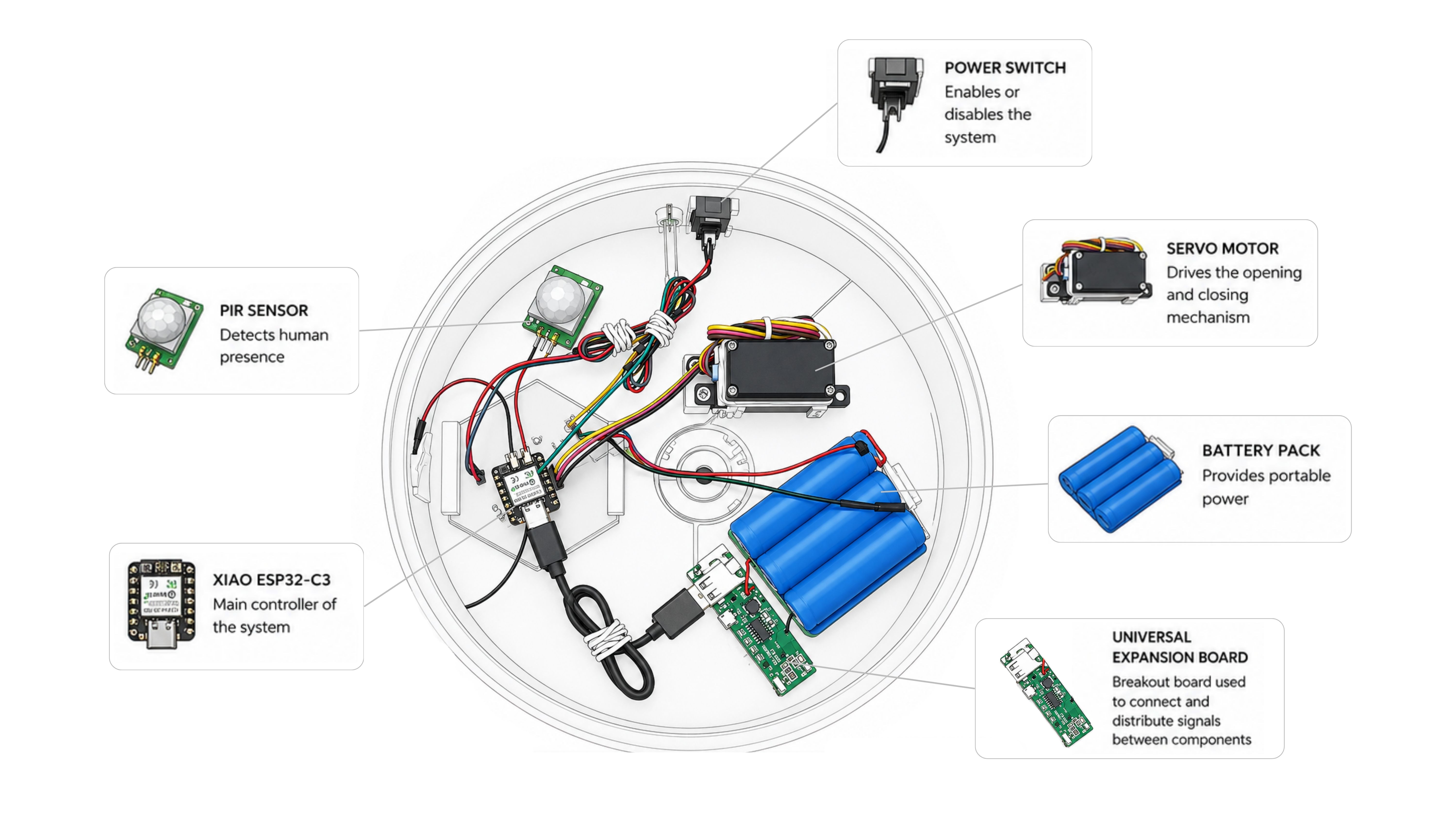
To facilitate the understanding of the integrated system, the main electronic and mechanical elements were mapped according to their position inside the enclosure. The diagram below provides a visual overview of the internal architecture, showing how sensing, control, actuation, and power subsystems are organized and connected within the final prototype.
2. System Logic
The interaction sequence follows this logic:
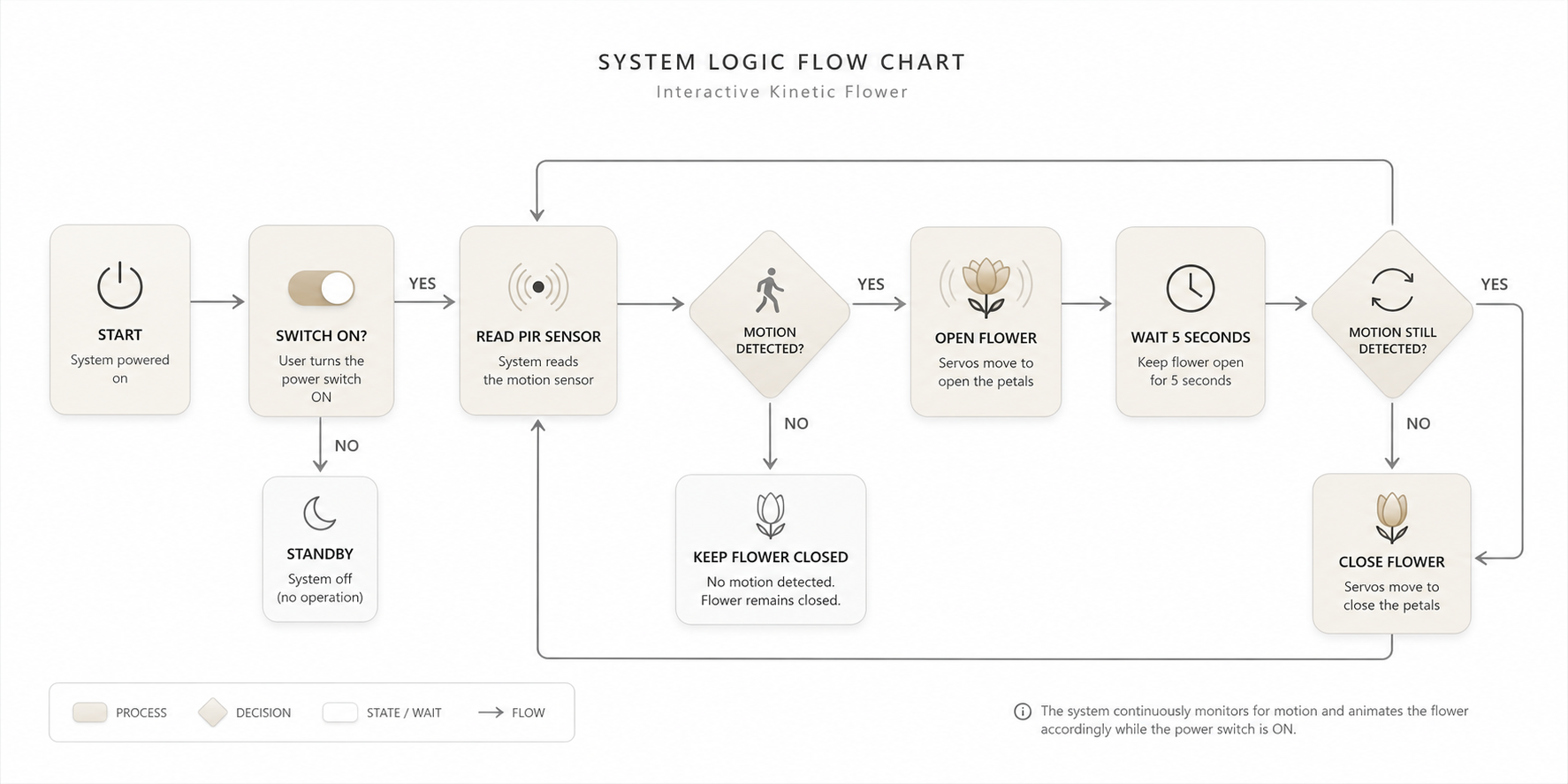
The flowchart illustrates the complete operational sequence of the system. Once the power switch is activated, the controller continuously monitors the PIR sensor. If motion is detected, the servo motor drives the mechanism to open the flower. The system then waits for a predefined period while continuing to monitor the sensor. If motion is still present, the flower remains open; otherwise, the servo returns the mechanism to its initial position and the flower closes. This logic creates a responsive interaction that directly links human presence with the kinetic behavior of the artifact.
The LED provides visual feedback indicating the operational state of the system.
3. Connection Diagram
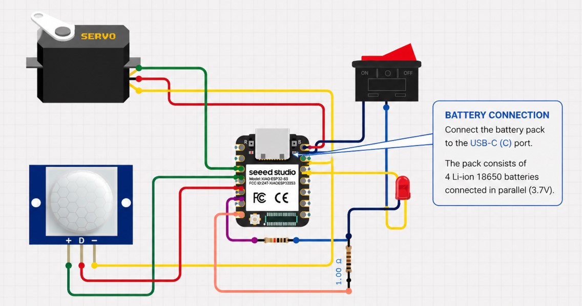
The following circuit configuration was tested during Week 10 and will be used as the base for the final project electronics:
- PIR sensor: connected to digital pin D4.
- Servo motor: signal connected to digital pin D3.
- Switch: connected to digital pin D5.
- LED: connected to digital pin D6 through a current-limiting resistor.
- Power: Battery power system.
In the final project, this same logic will be adapted to the physical structure of the flower. The PIR sensor will be placed in the center of the petals using a dedicated 3D-printed support, while the servo will be integrated into the lower central mechanism.
4. Code Used as Reference
#define PIR_PIN D4
#define SWITCH_PIN D5
#define LED_PIN D6

#include <ESP32Servo.h>

Servo myServo;

void setup() {
  Serial.begin(115200);

  pinMode(PIR_PIN, INPUT);
  pinMode(SWITCH_PIN, INPUT);
  pinMode(LED_PIN, OUTPUT);

  myServo.attach(D3);
}

void loop() {
  int encendido = digitalRead(SWITCH_PIN);

  Serial.print("button: ");
  Serial.println(encendido);

  delay(200);

  if (encendido == 1) {
    digitalWrite(LED_PIN, HIGH);

    int estado = digitalRead(PIR_PIN);

    Serial.print("pir: ");
    Serial.println(estado);

    if (estado == 1) {
      delay(200);
      myServo.write(0);
      delay(1000);
      myServo.write(180);
      delay(1000);
    } else {
      myServo.write(0);
    }
  } else {
    digitalWrite(LED_PIN, LOW);
    myServo.write(0);
  }
}
Code Explanation
The code begins by defining the pins used for the PIR sensor, switch, and LED. The servo motor is controlled using the ESP32Servo library, which allows the XIAO ESP32-C3 to generate the PWM signal required to move the servo to specific angles.
In the setup() function, the PIR sensor and switch are configured as digital inputs, while the LED is configured as a digital output. The servo motor is attached to pin D3, and serial communication is initialized to monitor the sensor and switch values during testing.
In the loop() function, the system first reads the state of the switch. If the switch is activated, the LED turns on, indicating that the system is enabled. Then, the PIR sensor is read. If motion is detected, the servo moves between 0° and 180°, generating the mechanical action required for the flower movement.
If no motion is detected, the servo remains in its initial position. If the switch is deactivated, the LED turns off and the servo returns to 0°, keeping the system at rest.
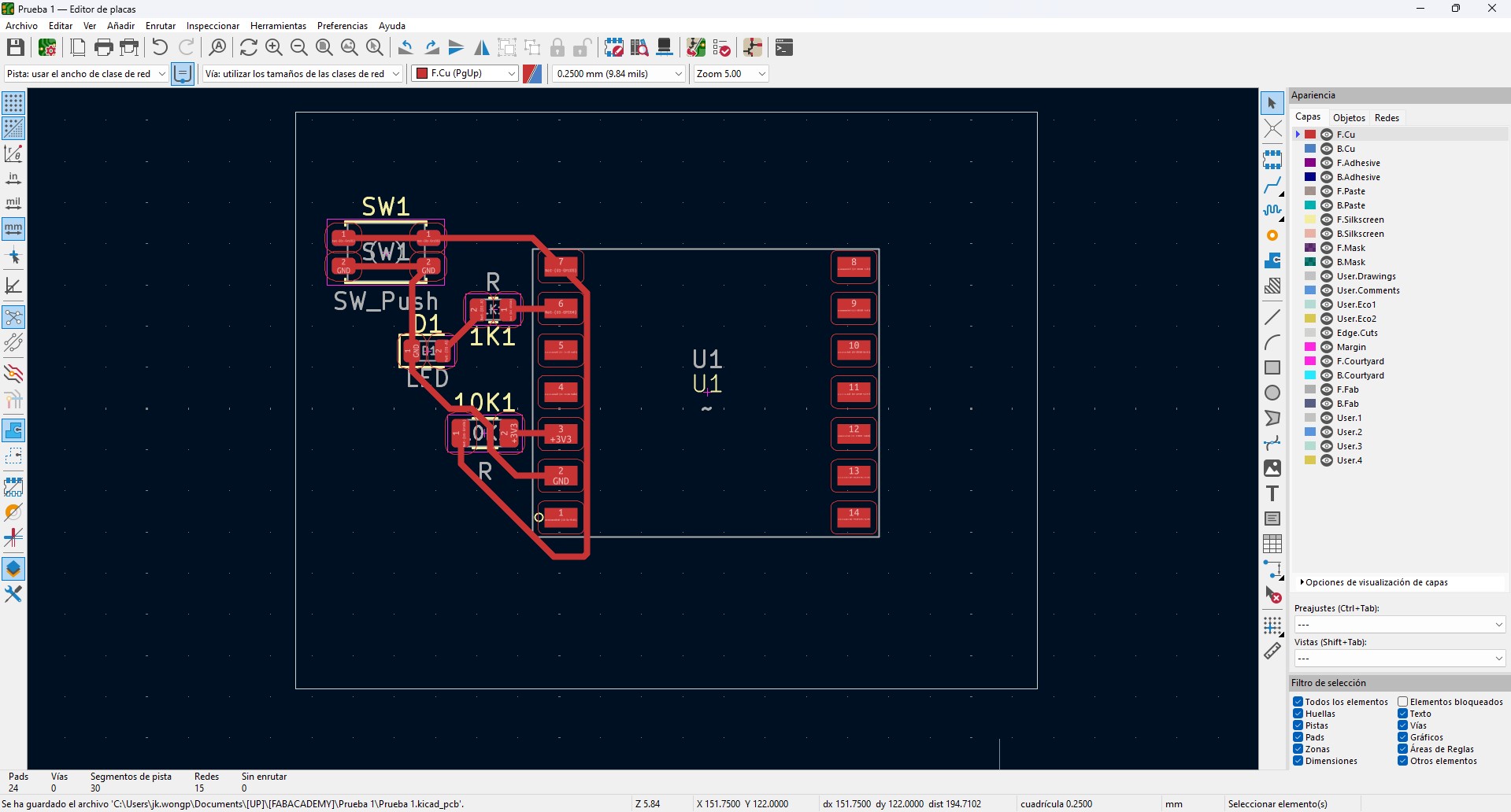
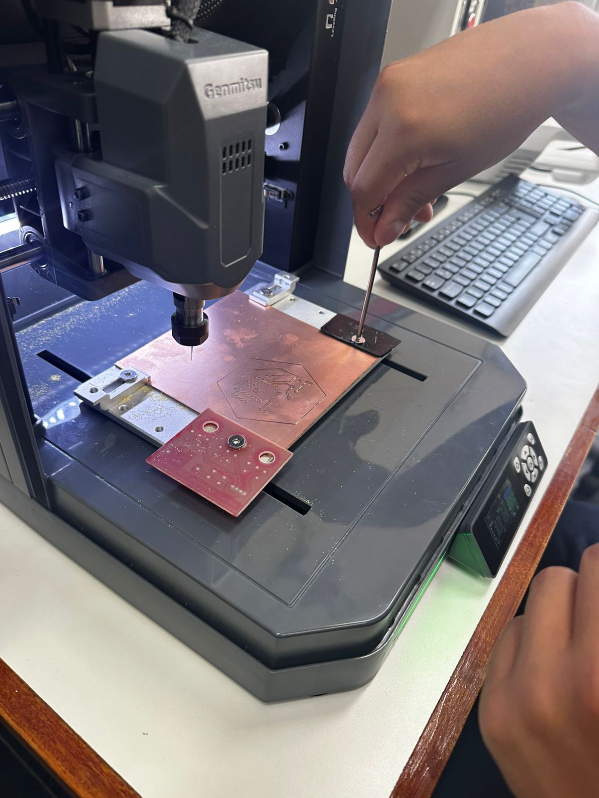
5. Custom PCB Design and Fabrication
To move from a temporary prototype to a stable system, a custom PCB was designed. This allowed the electronic components to be organized in a compact and reliable way, reducing wiring complexity and improving integration with the mechanical structure.
- Schematic design defining all electrical connections.
- PCB layout with organized routing and connection points.
- Generation of toolpaths for CNC milling.
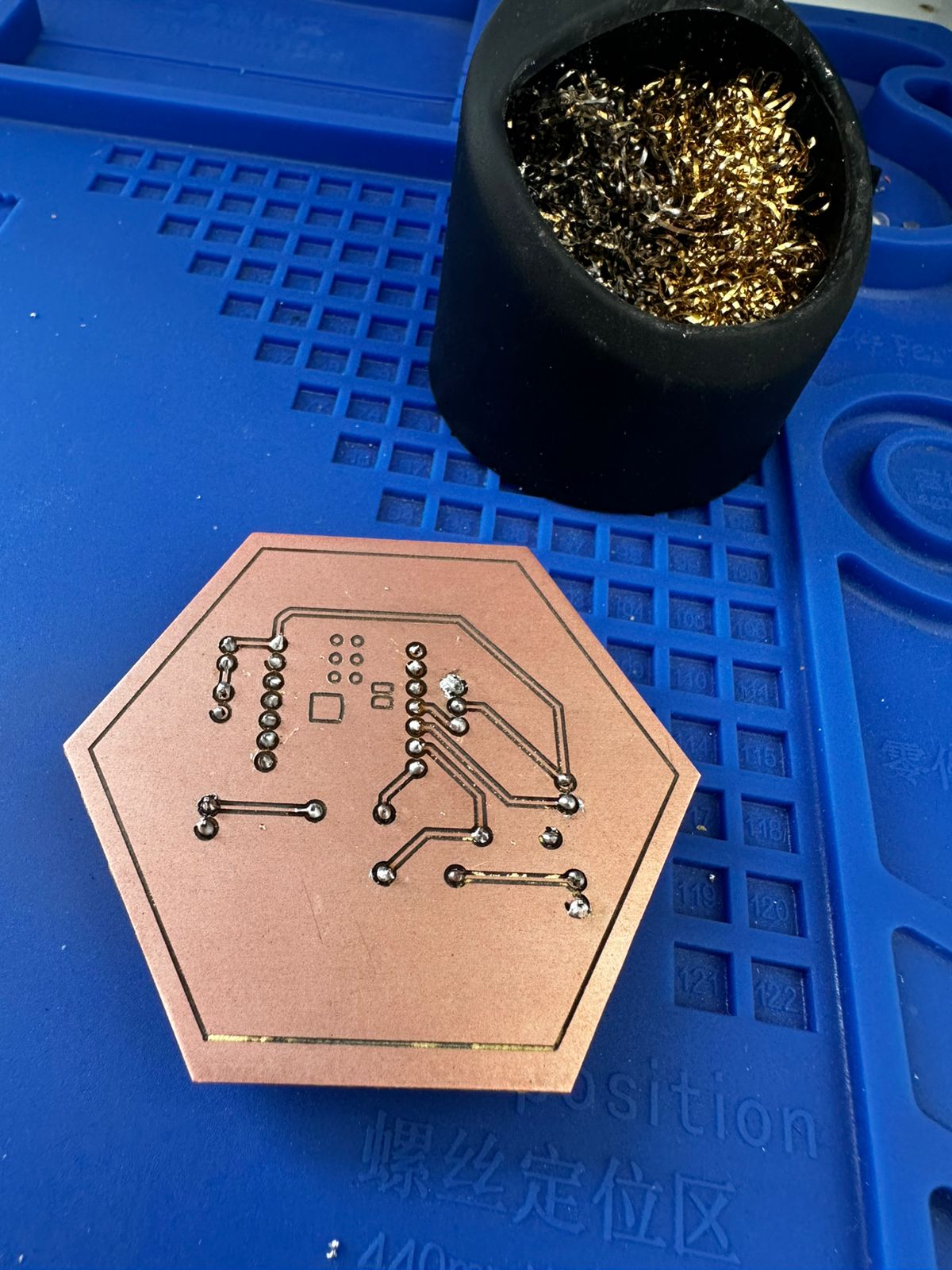
- Manufacturing of the board using a milling machine.
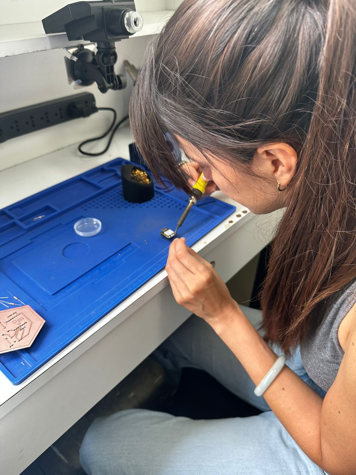
- Soldering of components and connectors.
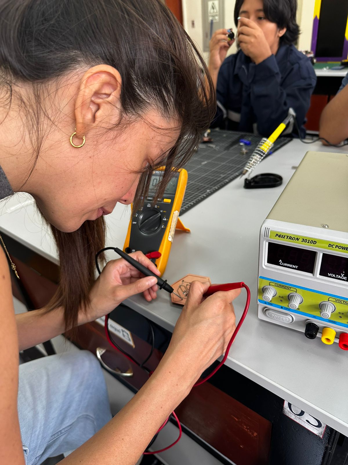
6. PCB Validation
Before integration, the board was validated to ensure correct operation:
- Continuity tests using a multimeter.
- Voltage and signal verification.
- Oscilloscope measurements to observe signal behavior.
- Functional tests controlling the servo and reading the PIR sensor.
7. Electronic System Validation
The electronic system was designed to be embedded within the structure:
- The PIR sensor is positioned at the center of the petals using a custom support, ensuring a clear detection area.
- The servo motor is mounted in the lower base and mechanically connected to the central mechanism.
- The PCB is placed inside the base, organizing connections and reducing exposed wiring.
This integration transforms the system from a test setup into a functional interactive object, where electronics and mechanics operate together.
For a more detailed explanation of the process, you can visit the corresponding assignment pages.
Considerations and Challenges
- Ensuring stable power supply for the servo motor.
- Avoiding noise or false triggering from the PIR sensor.
- Maintaining reliable connections after moving from breadboard to PCB.
- Aligning the servo movement with the mechanical system.
Download Files
The design files used in this assignment can be downloaded below.