
Group Assignment
This week's group assignment consisted of measuring the power consumption of an output device using laboratory measurement equipment. The objective was to understand how much current and power an output device consumes during operation and how this affects power supply requirements and circuit design.
The complete documentation of the group work can be found in the following page:
Group assignment documentation
Individual Assignment — Week 10
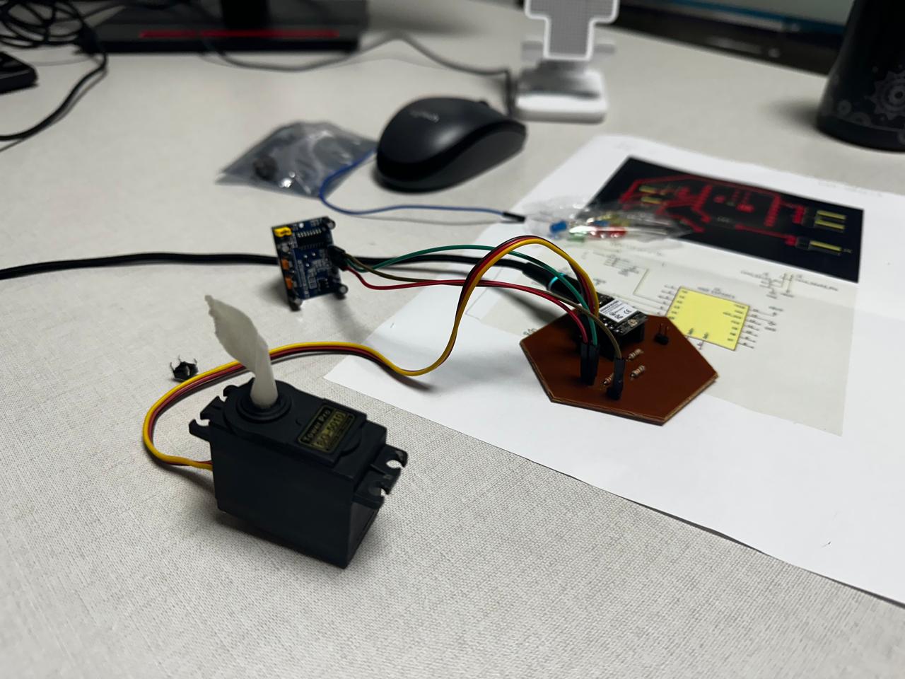
In this part of the assignment, an interactive output system was developed using the XIAO ESP32C3 board, a servo motor, a switch, and an LED. The objective was to understand how output devices respond to information received from sensors or digital inputs, and how to build an interactive system in which the microcontroller processes information and generates a physical or visual response.The process was not completed all at once, but progressively, by adding components step by step and verifying the operation of the system at each stage.
1. Electronic Board
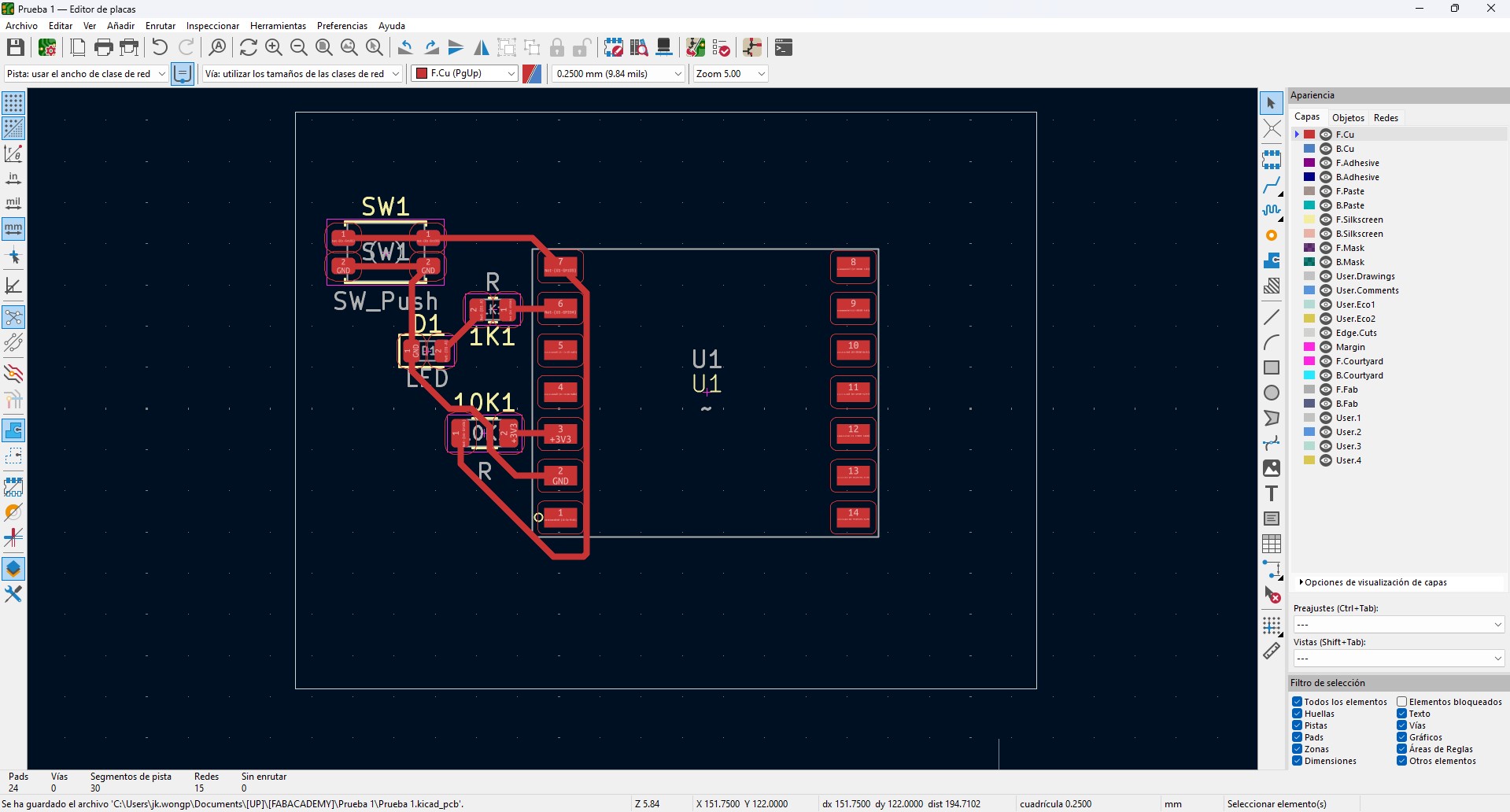
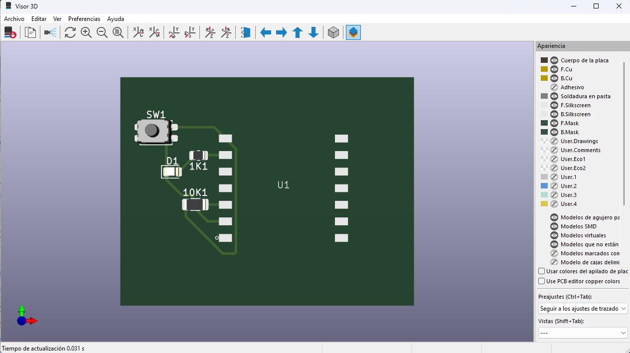
For this week, I worked again with the same custom electronic board used as the base of the system. The board was designed in KiCad, beginning with the schematic and then developed into the PCB layout.
The board is based on a XIAO ESP32 microcontroller, chosen for its compact dimensions and its processing and communication capabilities. The VBUS and GND lines were clearly organized and distributed to simplify the integration of external devices.
The board includes:
- 1kΩ resistors for current limiting in outputs
- 10kΩ resistors used as pull-down or pull-up resistors in inputs
- Header connectors for sensors and actuators
- Accessible pads to facilitate testing and electrical measurements
The PCB routing was made on a single side, optimizing the trace layout and avoiding crossings, which is important for CNC fabrication. The trace width was set to 0.4 mm, and adequate spacing was maintained to ensure proper milling.
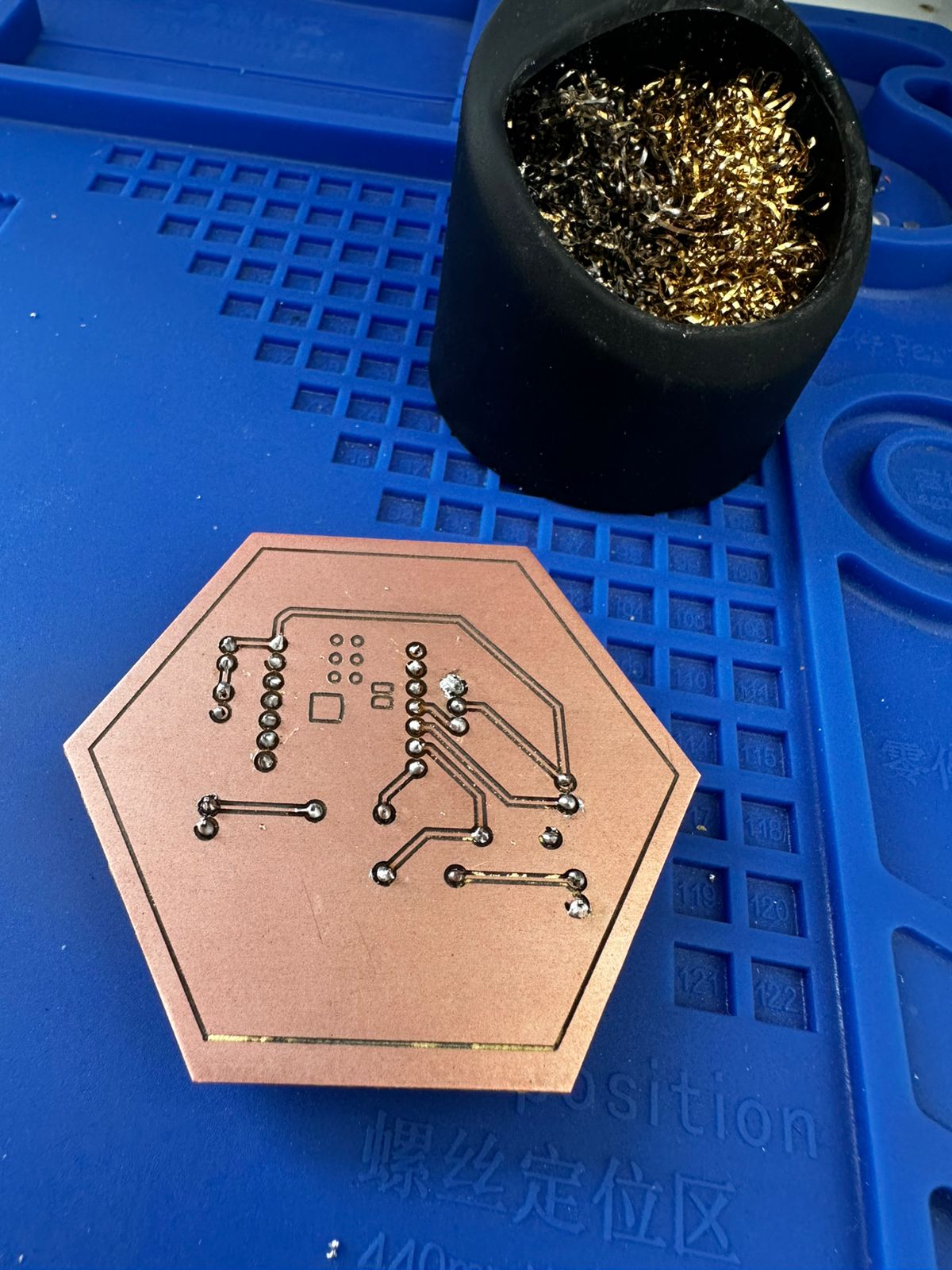
The fabrication process consisted of milling the copper board, manually drilling the required holes, and soldering the THT components. After assembly, continuity was verified with a multimeter and the circuit was tested to confirm its basic operation.
On top of this base, output devices such as a servo motor and an LED were connected. The board design allowed signal and power to be distributed efficiently, making it possible to control these devices directly from the microcontroller.
2. Circuit Diagram
The following diagram shows the connections between the XIAO ESP32C3 microcontroller and the output devices used in the system, including a servo motor and an LED.
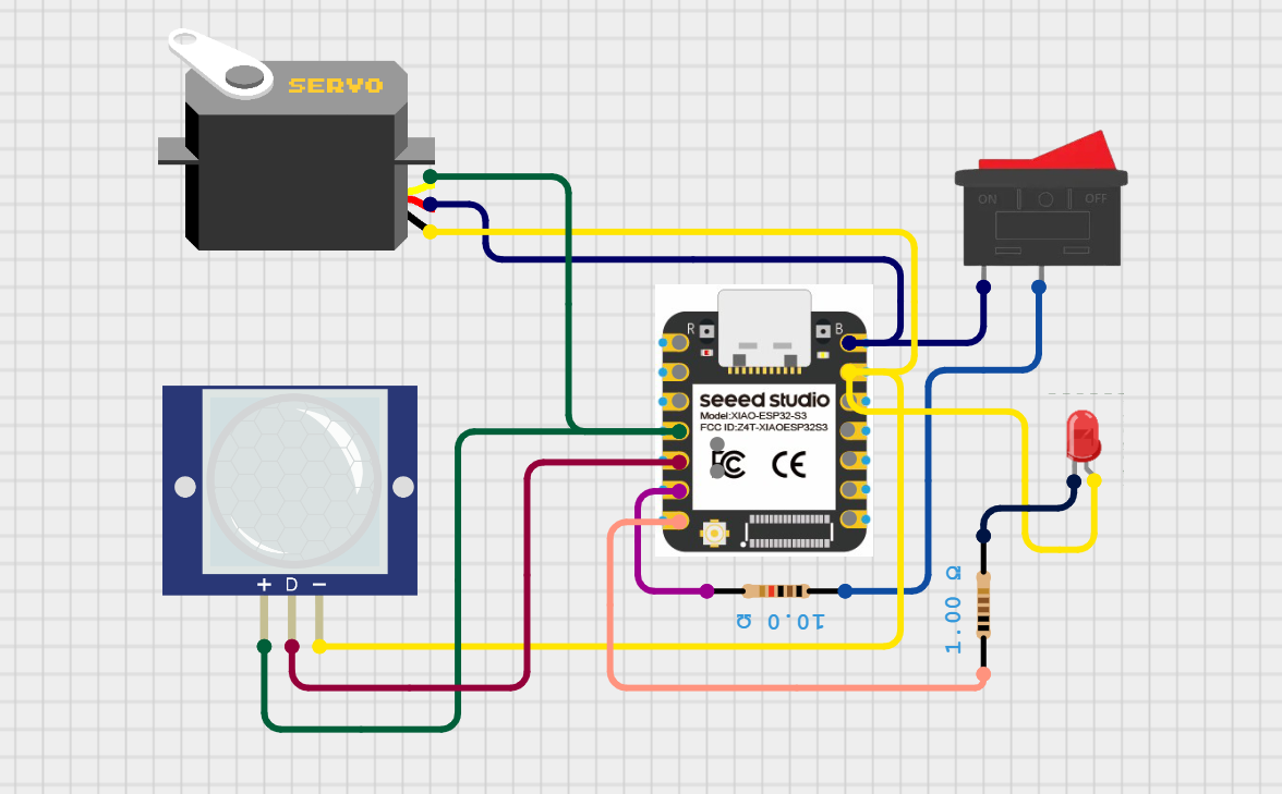
Circuit diagram showing the connection between the microcontroller and the output devices, where the system generates signals to control the servo motor and LED.
The servo motor is connected to a PWM-capable output pin of the microcontroller, allowing precise control of its angular position through pulse-width modulation signals. This enables the system to perform controlled mechanical movement in response to programmed conditions.
The LED is connected to a digital output pin through a current-limiting resistor. It acts as a visual indicator of the system state, turning ON or OFF depending on the signal sent by the microcontroller.
The focus of this configuration is to demonstrate how output devices can be controlled programmatically, allowing the system to generate physical responses based on input data or internal logic.
3. Servo Controlled by Sensor Information
The first stage consisted of controlling a servo motor according to the information coming from an input sensor. In this case, the sensor provided a digital signal (HIGH or LOW), and the servo motor responded by changing its position.
The servo was connected as follows:
| Servo | XIAO ESP32C3 |
|---|---|
| Red wire | 5V / VBUS |
| Brown wire | GND |
| Yellow | Digital pin D3 |
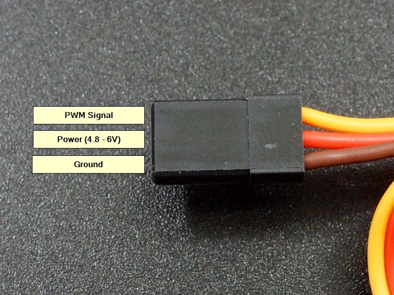
The servo operates through a PWM signal that allows it to move to a specific angle. To control the servo, the ESP32Servo library was used.
The system logic was the following:
- If the sensor detects motion or activation, the servo moves.
- If the sensor does not detect anything, the servo returns to its initial position.
This was the first step in building an interactive system in which the microcontroller not only receives information, but also acts physically on the environment.
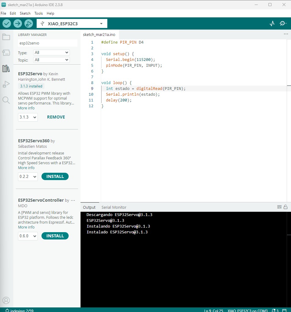
Code used:
#define PIR_PIN D4
#include

Servo myServo;

void setup() {
  Serial.begin(115200);
  pinMode(PIR_PIN, INPUT);
  myServo.attach(D3);
}

void loop() {
  int estado = digitalRead(PIR_PIN);
  Serial.println(estado);
  if (estado==1){
    delay(200);
      myServo.write(0);
    delay(1000);
    myServo.write(180);
    delay(1000);
  }
   else{
      myServo.write(0);

  }
}
Code Description
This program reads the signal from a PIR motion sensor and controls a servo motor based on the detected state.
-
#define PIR_PIN D4
Defines the digital pin where the PIR sensor is connected. -
#include <Servo.h>
Includes the Servo library required to control the servo motor. -
Servo myServo;
Creates a servo object to control the motor. -
void setup()
Initial configuration of the system:- Serial.begin(115200); Initializes serial communication for debugging.
- pinMode(PIR_PIN, INPUT); Sets the PIR sensor pin as an input.
- myServo.attach(D3); Connects the servo motor to pin D3.
-
void loop()
Main program loop:- int estado = digitalRead(PIR_PIN); Reads the sensor state (HIGH or LOW).
- Serial.println(estado); Sends the value to the Serial Monitor.
-
if (estado == 1)
If motion is detected:- Waits briefly to stabilize the reading.
- Moves the servo to 0°.
- Then moves it to 180° after a delay.
-
else
If no motion is detected:- Keeps the servo at the initial position (0°).
This logic allows the system to react to motion by generating a physical movement through the servo motor.
This stage helped to understand the relationship between: sensor → microcontroller → actuator.
The resultas are:
4. Integration of a Switch as System Control
In the second stage, a switch was added to the system in order to activate or deactivate the operation of the servo. In this way, the system was not always active, but could be manually controlled.
The switch was connected using a pull-down configuration:
| Switch | XIAO ESP32C3 |
|---|---|
| One side of the switch | 3.3V |
| Other side of the switch | Pin D5 |
| 10k resistor | Between D5 and GND |
Code used:
#define PIR_PIN D4
#define SWITCH_PIN D5

#include

Servo myServo;

void setup() {
Serial.begin(115200);
pinMode(PIR_PIN, INPUT);
pinMode(SWITCH_PIN, INPUT);
myServo.attach(D3);
}

void loop() {
int encendido = digitalRead(SWITCH_PIN);
Serial.print("boton:");
Serial.println(encendido);
delay(200);

if (encendido == 1) {
	int estado = digitalRead(PIR_PIN);
	Serial.print("pir:");
	Serial.println(estado);

	if (estado == 1) {
		delay(200);
			myServo.write(0);
		delay(1000);
		myServo.write(180);
		delay(1000);
	} else {
		myServo.write(0);
	}
}
}
Code Explanation
This program introduces a dual-input control system using a switch and a PIR sensor to manage the behavior of a servo motor. The switch acts as an activation condition, while the PIR sensor provides motion detection.
In the setup() function, both the PIR sensor (D4) and the switch (D5) are configured as input pins. Serial communication is initialized to monitor both signals independently, and the servo motor is attached to pin D3.
Within the loop(), the program first reads the state of the switch using digitalRead(). This value is printed to the Serial Monitor as "boton", allowing verification of the activation state.
The switch determines whether the system is active. Only when the switch is in the HIGH state (1), the program proceeds to read the PIR sensor. This creates a conditional structure where the sensor is evaluated only if the system is enabled.
When active, the PIR sensor value is read and printed as "pir" in the Serial Monitor. If motion is detected (value = 1), the servo performs a movement between 0° and 180°. If no motion is detected, the servo remains at its initial position.
This structure demonstrates a hierarchical control logic, where one input (switch) enables or disables the response to another input (PIR sensor), allowing more controlled and intentional system behavior.
With this configuration:
- When the switch is open, the pin reads 0.
- When the switch is pressed, the pin reads 1.
The system logic then changed to:
- If the switch is activated, the system runs.
- If the switch is deactivated, the servo does not respond to the sensor.
- If the switch is activated and the sensor detects motion, the servo moves.
This made it possible to introduce the concept of manual system control through an additional digital input, adding a new layer of interaction. The results are:
5. Integration of an LED as a System Indicator
In the third stage, an LED was added as a visual indicator of the system state. The LED makes it possible to know whether the system is active or not without checking the code or the Serial Monitor.
The LED was connected as follows:
| LED | XIAO ESP32C3 |
|---|---|
| Anode | Resistor → output pin |
| Cathode | GND |
Code used:
#define PIR_PIN D4
#include
#define SWITCH_PIN D5
#define LED_PIN D6

Servo myServo;

void setup() {
  Serial.begin(115200);
  pinMode(PIR_PIN, INPUT);
  myServo.attach(D3);
  pinMode(SWITCH_PIN, INPUT);
  pinMode(LED_PIN, OUTPUT);
}

void loop() {
  int encendido = digitalRead(SWITCH_PIN);
  Serial.print("boton:");
  Serial.println(encendido);
  delay(200);
  if (encendido==1){
    digitalWrite(LED_PIN, HIGH);
    int estado = digitalRead(PIR_PIN);
    Serial.print("pir:");
    Serial.println(estado);
    if (estado==1){
      delay(200);
        myServo.write(0);
      delay(1000);
      myServo.write(180);
      delay(1000);
    }
    else{
        myServo.write(0);

    }
  }
  else{
  digitalWrite(LED_PIN, LOW);
  }
}
Code Explanation
This program implements a system that combines two input devices (a switch and a PIR sensor) with two output devices (a servo motor and an LED), allowing both visual feedback and mechanical response.
In the setup() function, the PIR sensor and the switch are configured as input pins, while the LED is configured as an output. The servo motor is attached to pin D3, and serial communication is initialized to monitor system behavior.
In the loop(), the program first reads the state of the switch. This input acts as a main control that enables or disables the system. When the switch is activated (HIGH), the LED is turned ON, providing visual confirmation that the system is active.
Once enabled, the program reads the PIR sensor value. If motion is detected (value = 1), the servo performs a movement between 0° and 180°, generating a physical response. If no motion is detected, the servo remains at its initial position.
If the switch is turned OFF (LOW), the LED is also turned OFF, and the system does not respond to the PIR sensor, effectively disabling all outputs.
This configuration demonstrates how multiple inputs can be combined to control different types of outputs, integrating visual feedback (LED) and mechanical actuation (servo) within a single system.
The LED works as a simple digital output:
- HIGH → LED ON
- LOW → LED OFF
The final system logic was:
- The switch activates the system.
- When the system is active, the LED turns on.
- If the system is active and the sensor detects motion, the servo moves.
- If the system is deactivated, the LED turns off and the servo does not move.
In this way, a complete interactive system was built by combining:
- an input device (sensor),
- manual control (switch),
- visual output (LED),
- mechanical output (servo motor).
The results are:
6. System Architecture
The final system can be understood as a chain of information:
Switch → enables the system
Sensor → detects motion
Microcontroller → processes the information
Servo → generates movement
LED → indicates the system state
This flow represents a basic embedded system in which the microcontroller acts as the control unit between inputs and outputs.
Learning Outcomes
During this process, I learned:
- How to control a servo motor from a microcontroller.
- How to use a library to generate PWM signals.
- How to use a switch with a pull-down configuration.
- How to control an LED as a digital output.
- How to combine multiple inputs and outputs in the same system.
- How to design the logic of an interactive system.
- The importance of testing the system step by step instead of all at once.
- The relationship between hardware and software in embedded systems.
This exercise was important because it made it possible to move from individual tests to a more complex interactive system, which is essential for the development of the final project.
Conclusions
This week allowed me to understand how digital signals from a microcontroller can be translated into physical actions through output devices. By working with the servo motor and LED, I was able to explore both mechanical actuation and visual feedback as forms of system response.
One of the key learnings was the importance of selecting the appropriate control method for each output. While the LED operates with simple digital signals (ON/OFF), the servo requires PWM signals to achieve controlled movement. This highlighted the difference between discrete and continuous outputs.
The integration of multiple inputs and outputs demonstrated how system behavior can be structured through conditional logic. The use of a switch as an activation control and a PIR sensor as a trigger allowed the development of a more intentional and controlled interaction.
Additionally, the debugging process using the Serial Monitor was essential to verify the correct operation of the system. Observing real-time values helped identify issues related to sensor readings, timing, and response behavior.
Overall, this assignment reinforced the relationship between input data, processing logic, and output response, showing how microcontrollers can be used to create interactive systems that respond to environmental changes.
Download Files
The design files used in this assignment can be downloaded below.