

Concept
Inspiration and project vision
Explore the project through three sections: concept, development process, and final prototype.
Inspiration and project vision
Design and fabrication development
Final prototype and results
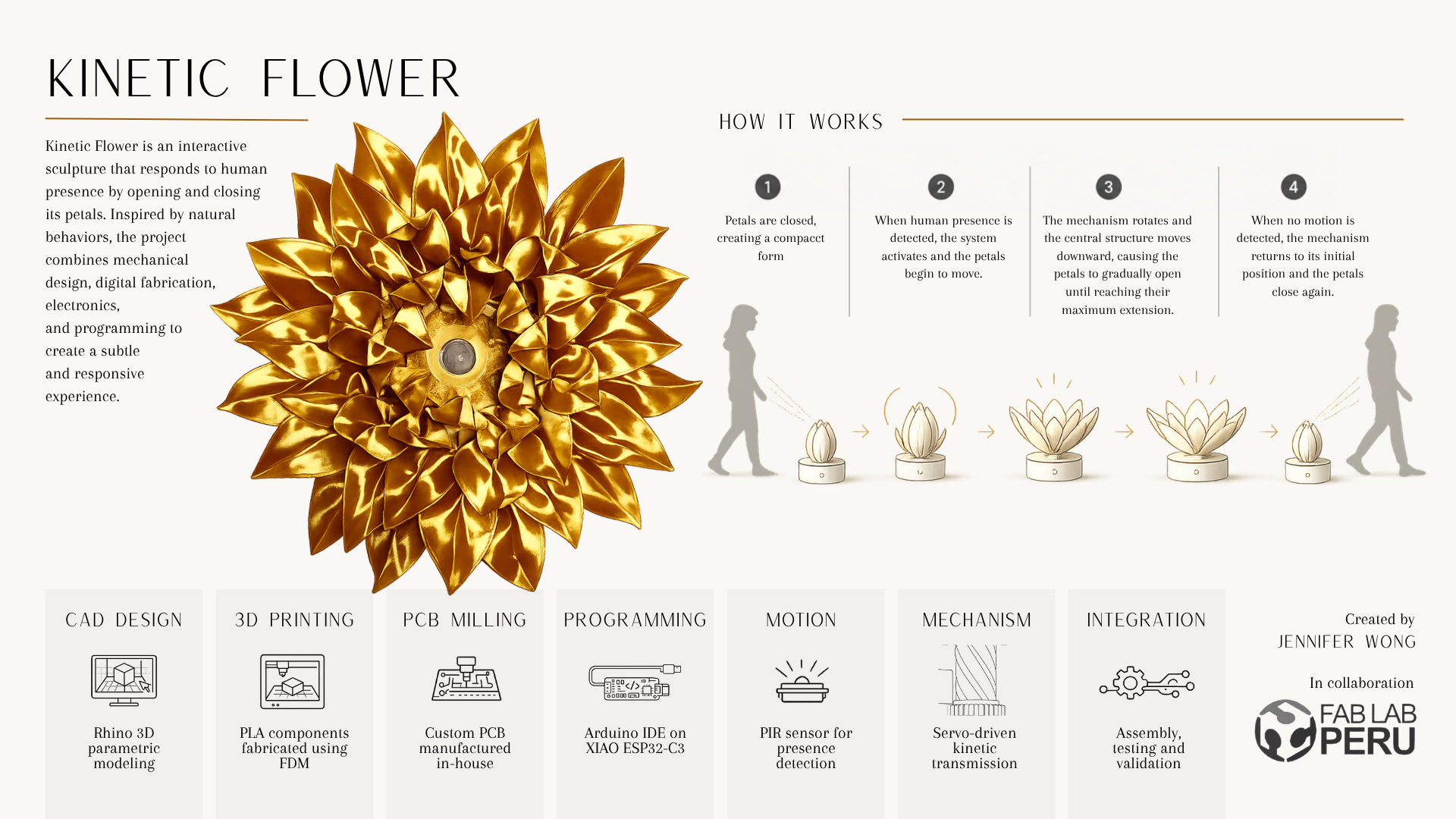
BLOOM is an interactive kinetic flower that responds to human presence. Using a PIR motion sensor, the system detects when a person approaches and activates a servo-driven mechanism that opens the flower petals. After a predefined period without movement, the petals automatically return to the closed position.
Beyond its mechanical function, the project explores a conceptual question inspired by perception and observation: does an artwork exist in the same way when nobody is observing it? The flower remains closed when no one is present and only reveals its complete form when an observer approaches, transforming presence itself into part of the artwork.
The project draws inspiration from kinetic sculptures, interactive installations, and biomimetic mechanisms that emulate natural movement. Artists and studios such as Refik Anadol, Random International, Studio Roosegaarde, Neri Oxman, and teamLab influenced the conceptual direction of the project through their exploration of interaction, perception, and responsive environments.
While similar interactive installations exist, the mechanical architecture, fabrication workflow, electronics integration, packaging system, and overall implementation were designed specifically for this project.
Materials
Electronic Components
Most electronic components were sourced from local electronics suppliers and Fab Lab inventory. Filament, cardboard, FR1 boards, and assembly materials were obtained from local fabrication suppliers. Digital fabrication equipment was provided through Fab Lab Peru facilities.
The estimated material cost of the project was approximately USD 70–80, including electronics, fabrication materials, packaging materials, and assembly hardware. The estimate does not include machine usage time or labor.
What worked
What didn’t
The project was evaluated through multiple iterations, subsystem testing, and final integration trials. Mechanical performance, motion detection reliability, electronic functionality, structural stability, power autonomy, and user interaction were validated progressively throughout the development process.
The final prototype was tested under real operating conditions to verify the complete interaction sequence from user detection to petal actuation and automatic closing.
BLOOM demonstrates how digital fabrication can be used not only to create functional systems but also to develop artifacts that encourage reflection and emotional engagement. The project combines engineering, electronics, programming, digital manufacturing, and handcrafted processes into a single interactive object.
By requiring the presence of an observer to reveal its complete form, the flower transforms interaction into part of the artwork itself. The project therefore functions both as a technical prototype and as a conceptual exploration of perception, presence, and observation.
More broadly, BLOOM illustrates how digital fabrication can serve as a bridge between engineering and artistic practice, opening opportunities for interactive installations, kinetic sculptures, responsive environments, and future explorations in computational and experiential design.