
Week 09 | Input Devices
Group Assignment
This week's group assignment consisted of probing input devices to analyze their analog levels and digital signals using laboratory measurement equipment. We used a multimeter to measure voltage levels and verify power connections, and an oscilloscope to observe signal behavior and waveform transitions from different input devices. This activity helped us understand the difference between analog and digital signals, how sensors communicate with microcontrollers, and how to correctly use measurement tools such as the multimeter and oscilloscope for signal analysis.
The complete documentation of the group work can be found in the following page:
Group assignment documentation
Individual Assignment — Week 09
In this week’s assignment, the objective was to work with input devices, meaning sensors that allow the microcontroller to receive information from the environment. For this exercise, I decided to work with a PIR sensor (Passive Infrared Sensor), which detects motion from people or warm objects through changes in infrared radiation.
The purpose of this exercise was to understand how to read digital signals from a sensor using the XIAO ESP32C3 board and the Arduino IDE environment, as well as to better understand the relationship between the electronic circuit and programming.
1. Electronic Board
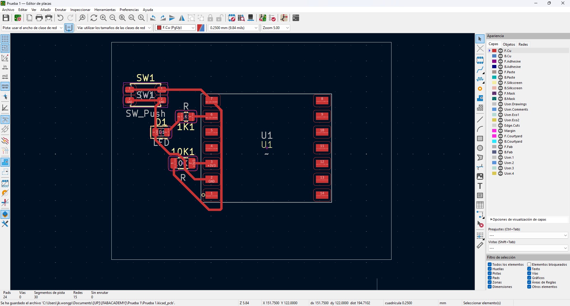
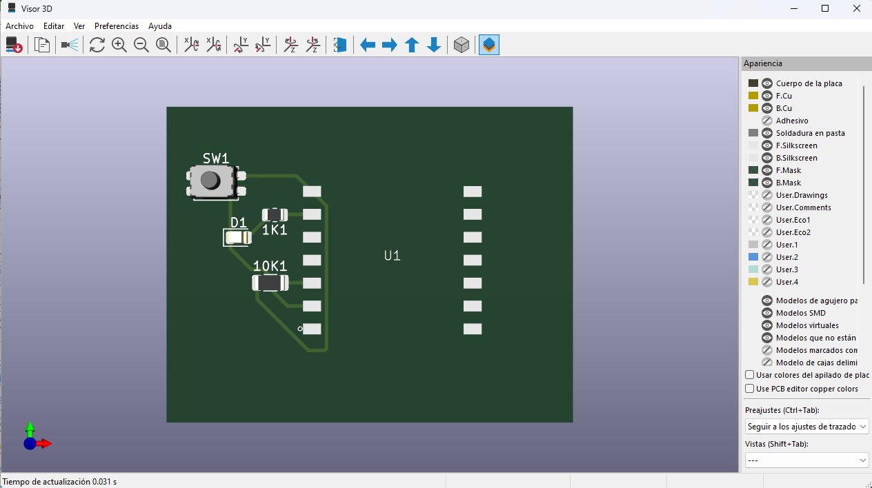
In this week, I used a custom electronic board that functions as the base of the system. The board was designed in KiCad, starting from the schematic design and then moving to the PCB layout.
The board is based on a XIAO ESP32 microcontroller, selected for its compact size and its processing and communication capabilities. The power lines (VBUS and GND) were clearly defined and strategically distributed to facilitate the connection of multiple components.
The board includes:
- 1kΩ resistors for current limiting in outputs
- 10kΩ resistors used as pull-down or pull-up resistors in inputs
- Header connectors for sensors and actuators
- Accessible pads to simplify testing and measurements
The routing was done on a single side, optimizing trace paths and avoiding crossings, which is essential for CNC milling. A trace width of 0.4 mm and proper spacing were carefully considered to ensure a clean fabrication process.
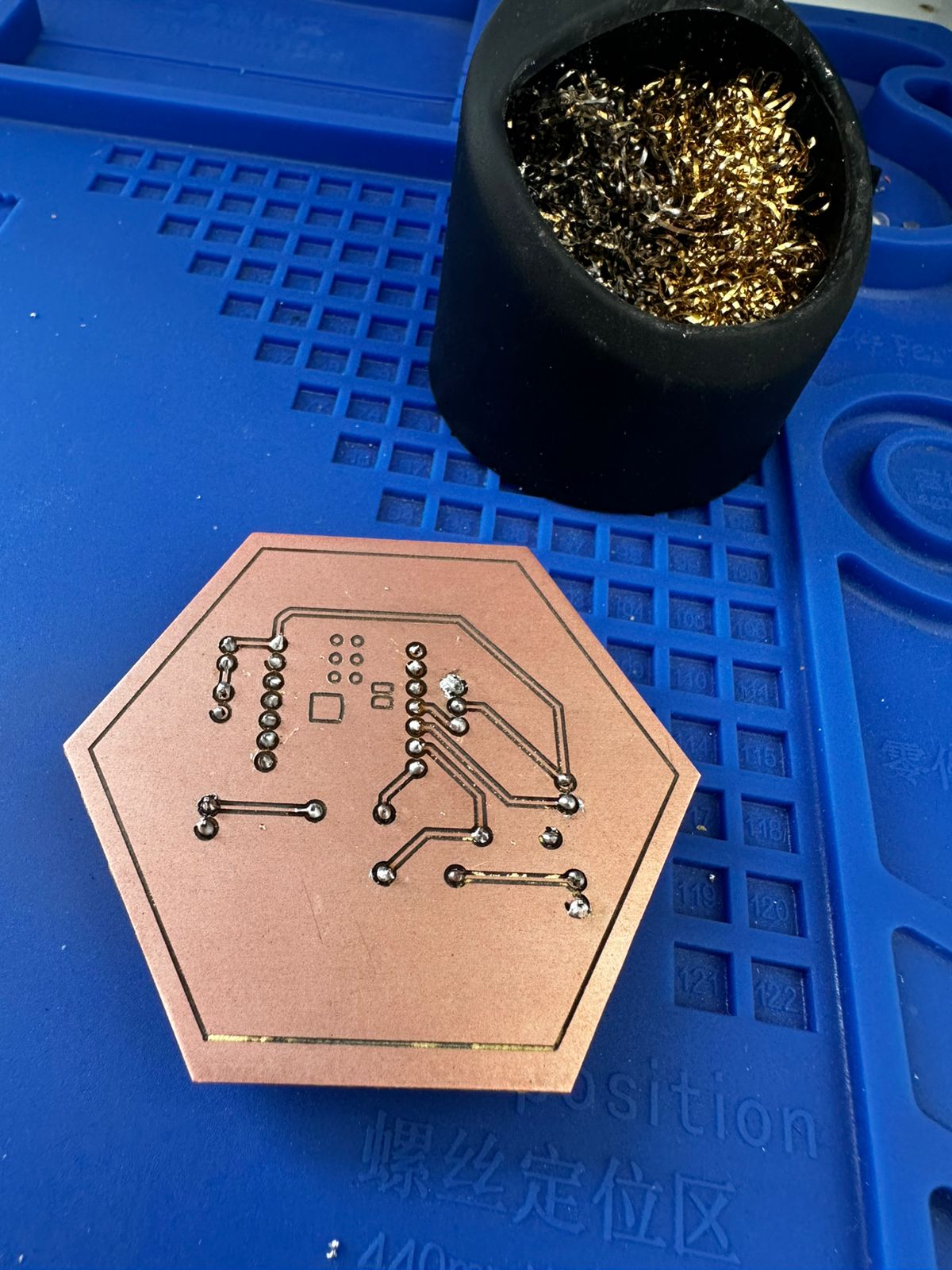
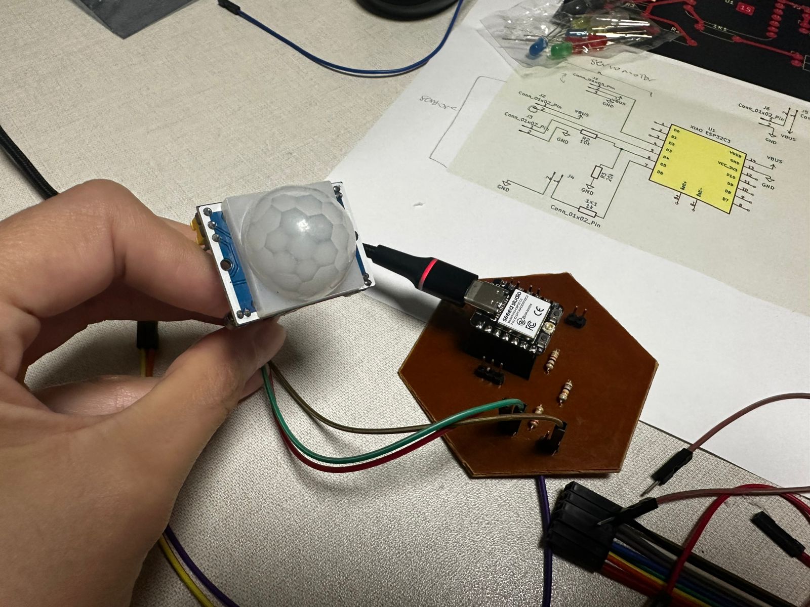
The board was manufactured by milling a copper-clad board, followed by manual drilling and THT component soldering. Finally, continuity was checked with a multimeter and the basic functionality of the circuit was validated.
Based on this platform, input devices were connected and tested. Since the board already had defined input pins and integrated resistors for signal stability, it was possible to connect devices such as a PIR sensor and a switch without redesigning the hardware.
2. Working Principle
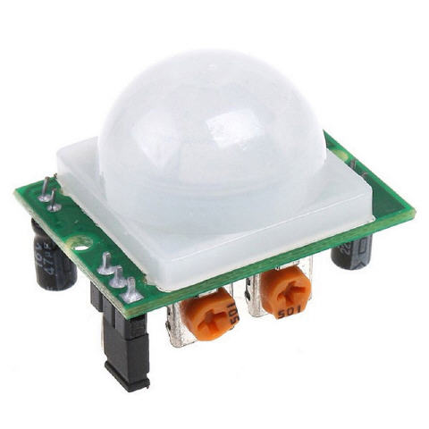
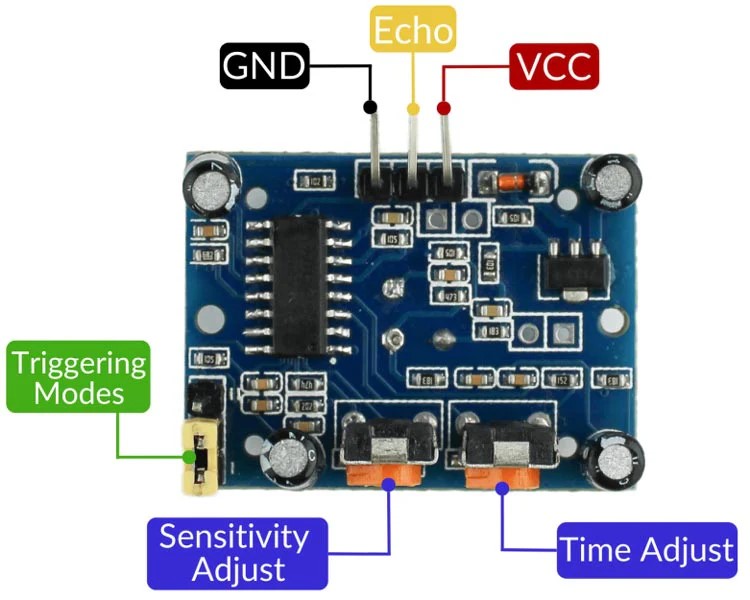
PIR Sensor
The PIR sensor detects changes in infrared radiation in the environment. It does not measure distance or static presence, but rather motion. When a person moves in front of the sensor, the output signal changes from LOW to HIGH.The sensor has three pins:
- VCC (power supply)
- GND (ground)
- OUT (digital signal)
The sensor output is digital:
- 0 → No motion detected
- 1 → Motion detected
This type of sensor is very useful for interactive systems, automatic lighting, security systems, and interactive installations.
Sensor Connection to the Microcontroller
To connect the PIR sensor to the XIAO ESP32C3 board, the following connections were used:
| PIR Sensor | XIAO ESP32C3 |
|---|---|
| VCC | VBUS / 5V |
| GND | GND |
| OUT | Digital pin (D4) |
It is important to power the sensor with 5V and share the ground with the microcontroller so that the digital signal can be read correctly.
3. Circuit Diagram
The following diagram shows the connections between the XIAO ESP32C3 microcontroller and the PIR sensor used as an input device in the system.
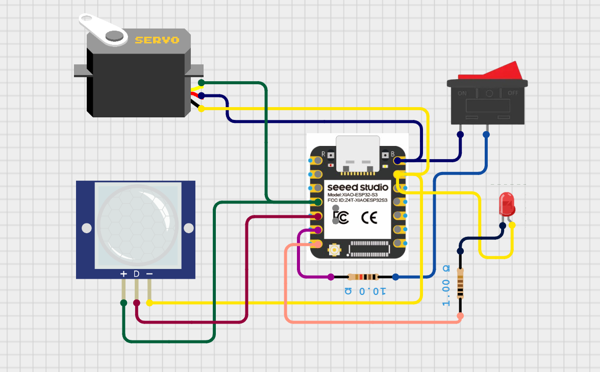
Circuit diagram showing the connection between the PIR sensor and the microcontroller, where the sensor provides a digital input signal based on motion detection.
The PIR sensor is connected to a digital input pin of the microcontroller. It outputs a HIGH (1) signal when motion is detected and a LOW (0) signal when no motion is present. This digital signal is read by the microcontroller and used to trigger different responses in the system.
The focus of this configuration is to demonstrate how an input device can be integrated and read in real time, enabling the system to react to changes in the environment.
4. Programming and Data Reading
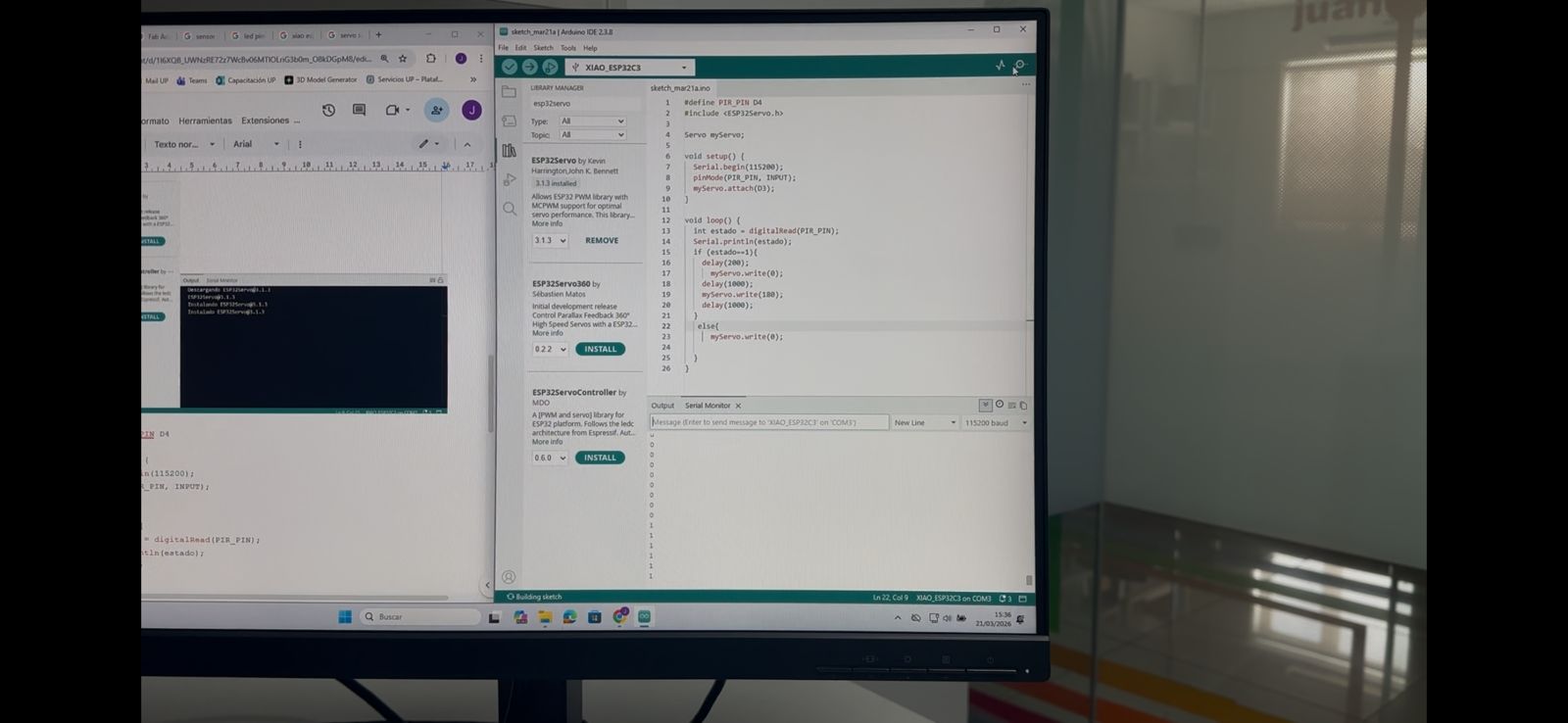
Arduino IDE was used to program the XIAO ESP32C3 board. The program reads the state of the digital pin connected to the sensor and sends the value to the Serial Monitor so the changes can be observed in real time.
Code used:
#define PIR_PIN D4

	void setup() {
	Serial.begin(115200);
	pinMode(PIR_PIN, INPUT);
	}

	void loop() {
	int state = digitalRead(PIR_PIN);
	Serial.println(state);
	delay(200);
						}
Code Explanation
This program is used to read and validate the behavior of a PIR (Passive Infrared) motion sensor as a digital input device.
In the setup() function, serial communication is initialized at 115200 baud rate to allow real-time monitoring of the sensor output. The PIR sensor pin is configured as an input, enabling the microcontroller to receive its signal.
In the loop(), the sensor state is continuously read using digitalRead() and stored in the variable state. The PIR sensor outputs a HIGH (1) signal when motion is detected and a LOW (0) signal when no motion is present.
The value is printed to the Serial Monitor using Serial.println(), allowing observation of the sensor response and verification of its correct operation. A short delay of 200 milliseconds is included to stabilize the readings and improve readability.
This program makes it possible to visualize values of 0 and 1 in the Serial Monitor depending on whether the sensor detects motion or not.
5. Testing and Debugging Process
During the testing process, it was necessary to verify several aspects:
- Correct Arduino IDE configuration for the XIAO ESP32C3 board.
- Selection of the correct COM port.
- Verification of the sensor power supply.
- Checking the digital pin connection.
- Using the Serial Monitor to verify the sensor readings.
- Resetting the board when the port was busy or when uploading failed.
The Serial Monitor was used to validate the sensor behavior, allowing real-time observation of the digital signal. The change between HIGH (1) and LOW (0) confirms that the sensor is correctly detecting motion and responding accordingly.
I also learned that the PIR sensor requires a stabilization time after powering on (approximately 30–60 seconds), during which it may provide inaccurate readings.
6. Results
After making the connections and uploading the program, it was possible to observe in the Serial Monitor that:
- When there was no motion, the sensor sent a value of 0.
- When motion was detected in front of the sensor, the value changed to 1.
This confirms that the sensor works correctly as a digital input device.
Learning Outcomes
In this part of the assignment, I learned:
- How to connect a digital sensor to a microcontroller.
- How to read digital signals using Arduino.
- The difference between input and output devices.
- The importance of power supply and ground connections.
- How to use the Serial Monitor to debug electronic systems.
- That many errors are not related to programming, but to electrical connections.
- The importance of testing the microcontroller first and then the sensor.
- The debugging process in embedded systems.
This exercise is important because it builds the foundation for interactive systems, where the microcontroller must react to information from the environment provided by sensors.
Conclusion
Working with the PIR sensor and the XIAO ESP32C3 board made it possible to understand how digital input devices work and the complete process from electronic connection to data reading through programming. This knowledge will be fundamental for the development of the final project, where sensors will be integrated to generate interactions with actuators and mechanical systems.
Download Files
The design files used in this assignment can be downloaded below.