FABI – Final Project
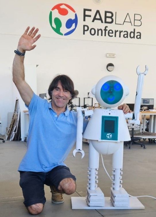
A robot that rewards good environmental actions with a hug
FABI is an interactive robot developed for Fab Academy. It combines 2D and 3D design, additive and subtractive fabrication, electronics design and production, embedded programming, MQTT communication, cloud control, mobile interaction and full system integration into a friendly robot for children.
Evaluable: Eye PCB Evaluable: ToF + Servo PCB Extra: Robotic Arms Extra: Heart Matrix Extra: Cloud + App
What does it do?
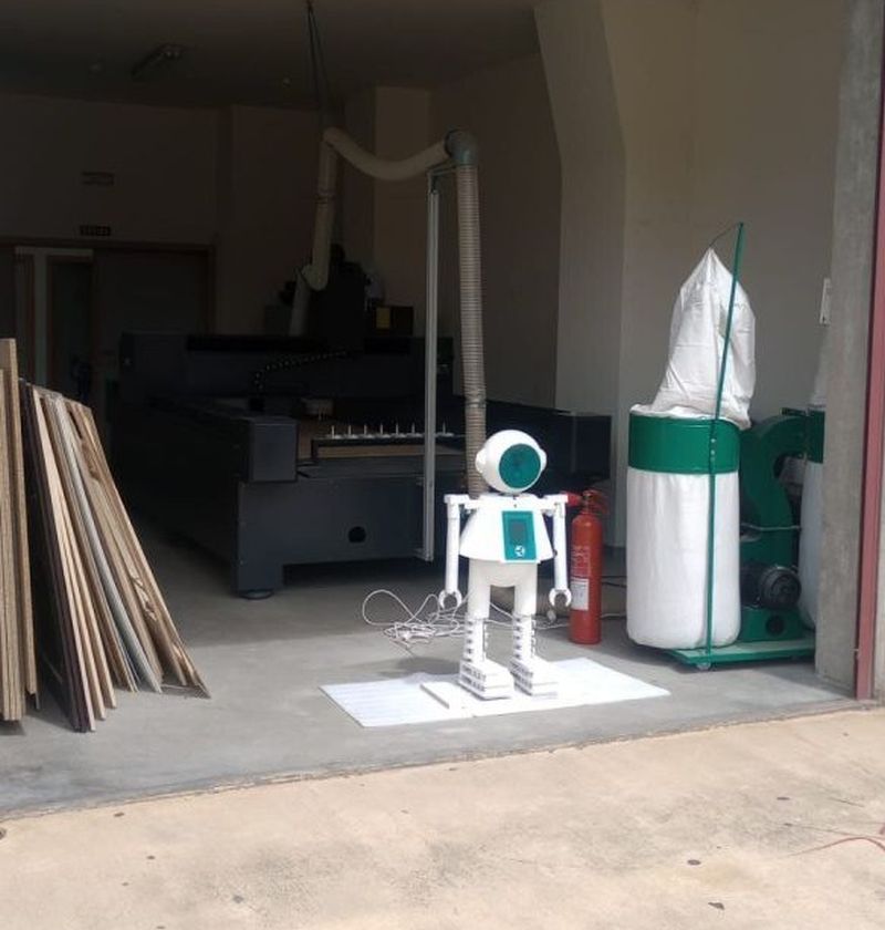
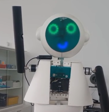
FABI is a friendly robot designed to attract children to the Fab Lab and promote environmental awareness. The robot detects interaction using a ToF sensor, reacts with lights, moves its arms, displays emotional feedback through a heart and eyes, and can be controlled through a cloud-based MQTT system and a mobile app.
Project Summary Slide and Video
The final project includes the required summary slide and a one-minute video showing the conception, construction and operation of FABI.
Open presentation.png Open presentation.mp4Who's done what beforehand?
FABI was inspired by educational robots, social robots, interactive installations and Fab Academy robot projects. The objective was not to copy an existing robot, but to create my own integrated design adapted to the identity of Fab Lab Ponferrada.
The final shape was inspired by the Fab Lab Ponferrada mascot, but the mechanical structure, electronics, programming, integration and interaction system were designed and fabricated as part of my individual Fab Academy final project.
Design Process and Technical Development
FABI was developed through an iterative process combining mechanical design, electronics design, digital fabrication, embedded programming and cloud integration.Detailed explanations of how each part was designed and fabricated can be found in the corresponding weekly assignments. At the end of this page, you will find links to download all the design files, source code, and project components. Click on each section to explore the development process.
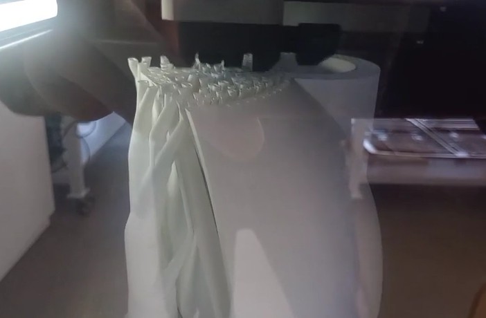
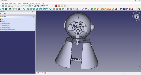
The complete mechanical structure of FABI was designed in FreeCAD. I used FreeCAD for the full external structure and the main body of the robot, including the head, body, lower body, internal supports and spaces for electronics.
The design was created as a modular structure so that the parts could be fabricated separately, assembled with screws and modified during the development process. The first CAD version helped define the general shape, while the final model included the real dimensions of the components and the final assembly strategy.
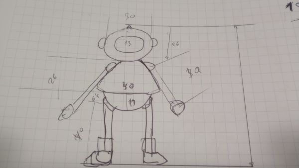
First steps the skecht
First steps in my computer design process, starting with the head and body based on the measurements taken from the initial sketch.

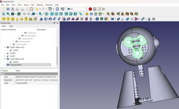
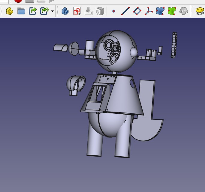
Final design with all parts in the same design
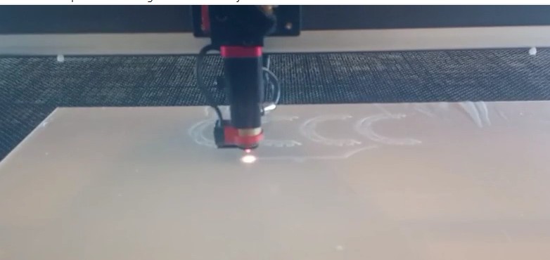
For the 2D design, I used RDWorks V8. The design was based on simple geometric shapes such as rectangles and squares. These parts were used for flat structural and decorative elements that could be fabricated using the laser cutter.
This approach made the design easy to modify and fast to fabricate. It also helped me adapt the pieces to the real dimensions of the robot during the assembly process.
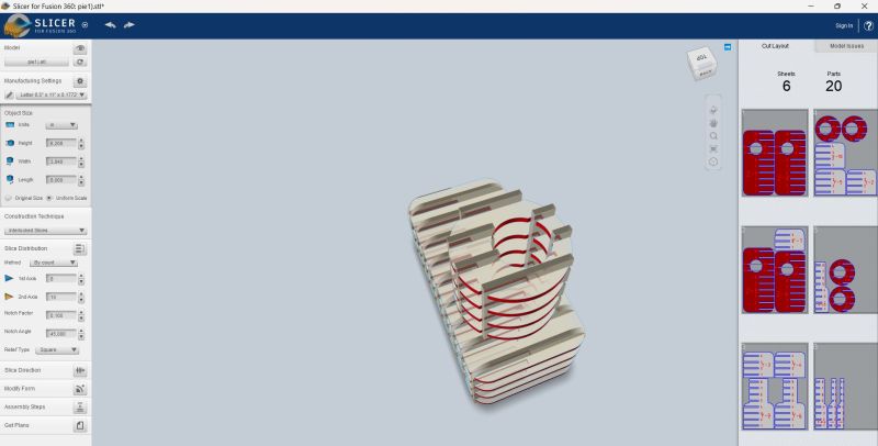
design using stl from Freecad and slicer for Fusion
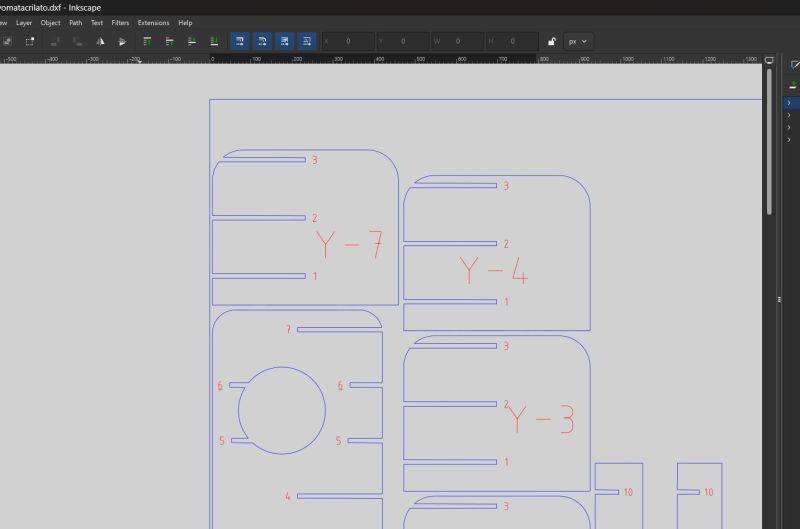
Desing with inkscape
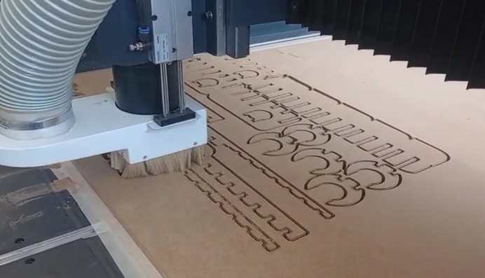
Working with CNC with this design
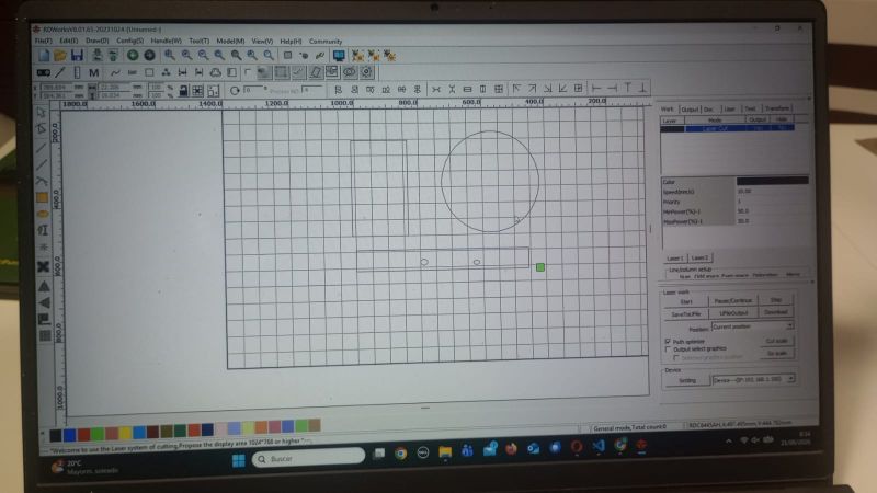
Using the 2D design software RDWorks for laser cutting.
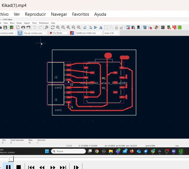
One of the evaluable parts of the final project is the custom PCB for the robot eyes. This board was designed in KiCad and uses a XIAO ESP32-S3 to control the LED eyes.
This PCB is an output board because it controls the visual expression of the robot. The board includes the microcontroller, connectors and the necessary routing to connect the LED elements inside the head.
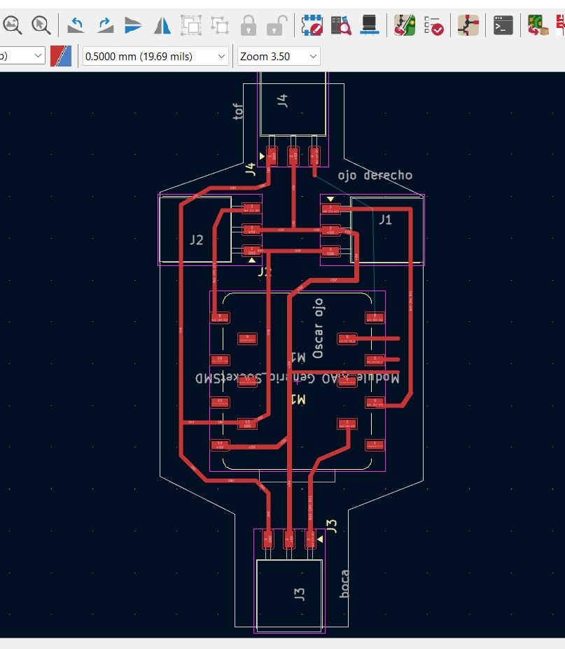
The PCB was designed in KiCad, and the design files can be found at the end of this page. The board was specifically created for integration into the 3D-printed eyes.
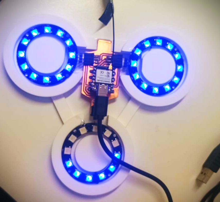
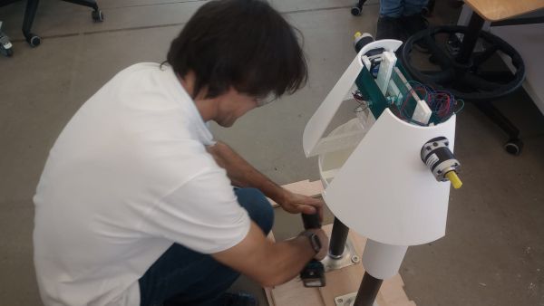
All integration working
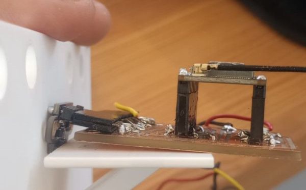
The second evaluable PCB integrates the ToF distance sensor and the servo output. This board is also based on a XIAO ESP32-S3 and was designed in KiCad.
The ToF sensor works as an input device. When a person approaches the robot, the sensor detects the presence and the microcontroller activates a servo motor to open the trash compartment.
This board demonstrates both input and output integration in a custom fabricated PCB.
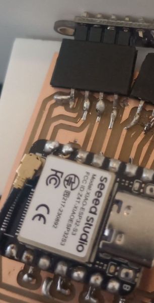
This PCB was designed around a XIAO ESP32-S3 and controls both the trash gate servo and the ToF sensor. The ToF sensor is mounted directly onto the PCB in a perpendicular orientation, as shown in the detailed photograph. This configuration allows the entire assembly to fit neatly inside the robot body without additional wiring. The only external connections required are the servo cable and the power supply, which must remain separate from the board due to their electrical and mechanical requirements.
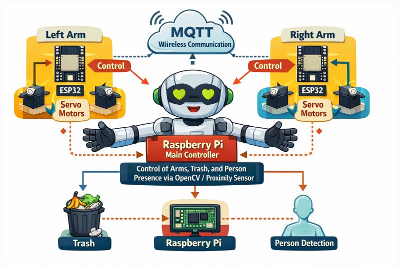
As an extra feature beyond the minimum Fab Academy requirements, I implemented the arm control system using an M5Stack ATOM Matrix based on the ESP32. Through the cloud integration, the ATOM Matrix receives data from the proximity sensor via MQTT and controls the arm movements, raising or lowering them depending on the interaction sequence. It can also communicate with the mobile application through MQTT, enabling remote control and monitoring. I chose the ATOM Matrix because, in addition to its compact size and wireless connectivity capabilities, it includes an integrated LED matrix that allows me to implement a beating heart inside the robot, adding an emotional and engaging element to enhance the user experience.
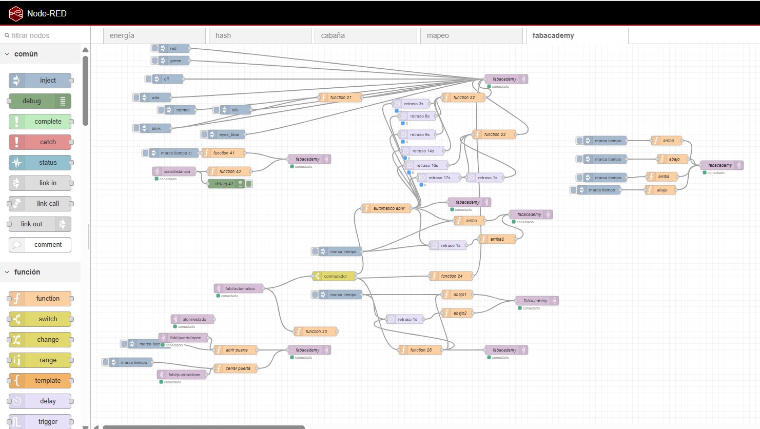
The different controllers communicate through MQTT topics. Node-RED acts as the central platform in the cloud, receiving commands and coordinating the robot subsystems.The ATOM Matrix sends the control signals to the stepper motor drivers, which regulate the movement, speed, and direction of the robotic arms.
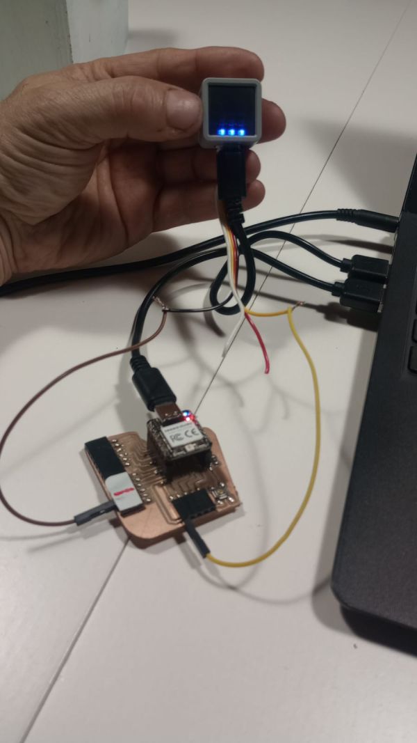
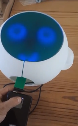
Initial tests of the ATOM Matrix and MQTT communication with the other custom PCBs designed and fabricated for this project. The ATOM Matrix, shown in my hands, acts as the central controller for the robot's interaction system. During these tests, it successfully exchanged data with the eye PCB and the ToF and servo PCB through MQTT, validating the cloud-based communication architecture and the integration of the different subsystems.
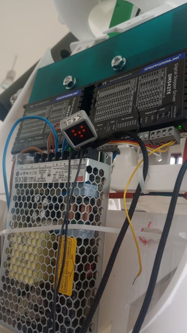
test The ATOM Matrix sends the control signals to the stepper motor drivers, which regulate the movement, speed, and direction of the robotic arms.
Test the stepper motor drivers, which regulate the movement
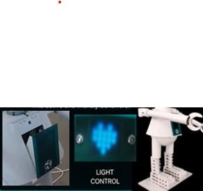
Final appearance of the ATOM Matrix with the animated heart display. The beating heart effect can be clearly seen in the presentation video, where it enhances the robot's emotional interaction and reinforces its friendly and engaging character.
As an extra feature beyond the minimum Fab Academy requirements, I implemented cloud control using Node-RED and MQTT.
The different controllers communicate through MQTT topics. Node-RED acts as the central platform in the cloud, receiving commands and coordinating the robot subsystems.
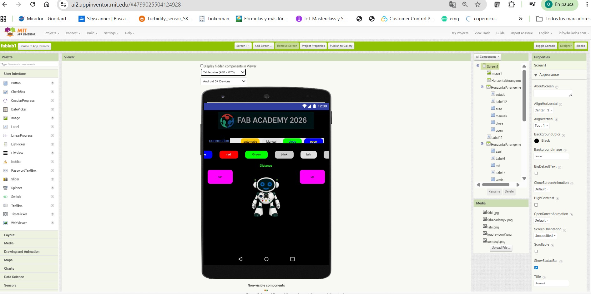
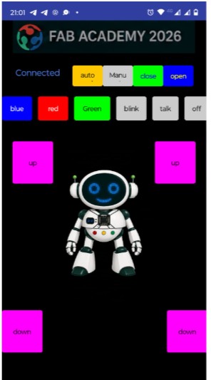
I also developed a mobile application using MIT App Inventor. The app allows the user to interact with the robot and send commands to the cloud system.
This app communicates with Node-RED through MQTT, making it possible to control the robot remotely and test its different behaviours.