Week 10 – Output Devices
This week is focused on Output Devices: understanding how to connect an actuator to a microcontroller, how to control it correctly, and how to evaluate its electrical behaviour, especially its power consumption.
On this page I document:
- The group assignment: measuring the power consumption of an output device.
- My individual assignment: adding an output device to a microcontroller board I designed and programming it to do something.
- The design and fabrication workflow of the board or module used.
- How the code works and how I controlled the actuator.
- The problems I found and how I solved them.
- The design files, source code and a hero shot of the final board.
Assignment and Learning Outcomes
The weekly assignment is:
- Group assignment:
- Measure the power consumption of an output device.
- Individual assignment:
- Add an output device to a microcontroller board you've designed.
- Program it to do something.
The learning outcomes are:
- Understand how to interface output devices with a microcontroller.
- Measure and interpret power consumption of an actuator.
- Control an actuator safely through hardware and software.
- Relate the weekly work to the final project.
Checklist
In this page I answer the required questions:
- Linked to the group assignment page.
- Documented how I determined the power consumption of an output device with my group.
- Documented what I learned from interfacing and controlling output devices.
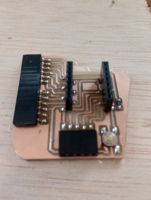
- Linked to the board made previously or documented the new design and fabrication process.
- Explained how my code works.
- Explained the problems and how I fixed them.
- Included the original design files and source code.
- Included a hero shot of my board.
You can see the group documentation here:
Espiral 1 – Available Actuators and Selection
Following the recommendation from the local instructors, I first reviewed the actuators available in the lab and selected several options that could fit my final project.
The goal of this first spiral was not only to complete the weekly assignment, but also to explore devices that could later be integrated into my final system.
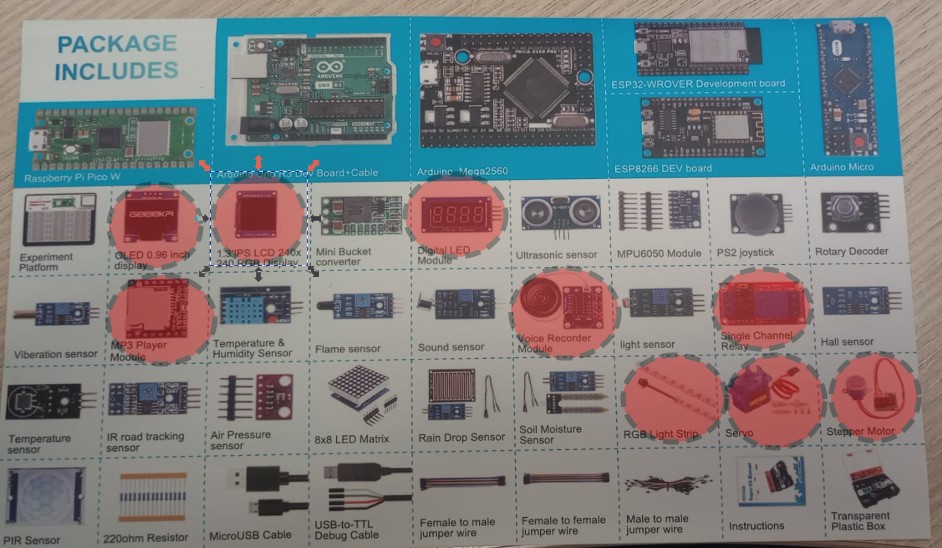
Actuators considered
- OLED 0.96 inc – display OLED .
- 1,3 IPS LCD – display RGB 240x240.
- Digital Led – Digital led module .
- MP3 player module – MP· player module
- Rele – imple channel rele
- RGB LED – simple visual feedback and easy PWM control.
- Servo motor – controlled movement, useful for mechanical interaction.
- Stepper motor – stepper, useful for dynamic systems.
Why these options are interesting for my final project
I tried to choose actuators that are not only easy to test during this week, but also meaningful for future integration into my final prototype.
After comparing complexity, usefulness, power requirements, and ease of control, I decided to continue with the stepper motor and the servo motor.
Group Assignment – Measuring the Power Consumption of an Output Device

For the group assignment we measured the power consumption of an output device. The objective was to understand how much current the actuator draws, what voltage it needs, and how this affects the design of the circuit and the power supply requirements.
This is important because output devices usually require more current than sensors, and in many cases they cannot be driven directly from a microcontroller pin.
Equipment Used
- Multimeter in current measurement mode.
- Power supply or USB supply.
- Output device under test.
- Microcontroller board or test circuit.
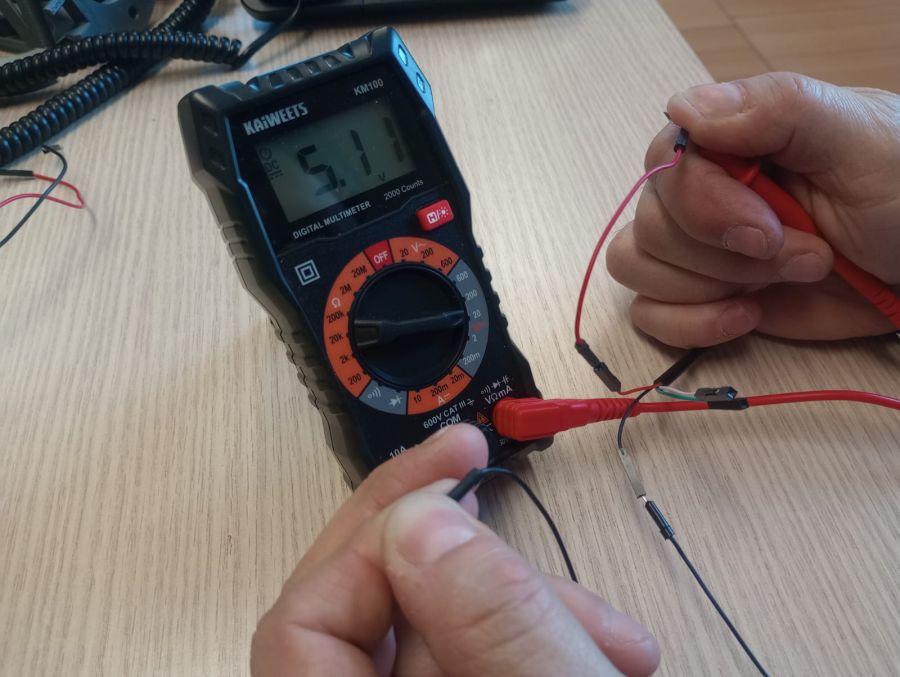
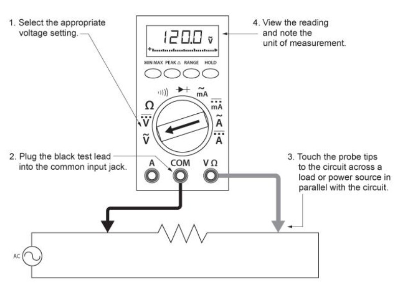
Measurement Procedure
- We identified the voltage required by the output device.
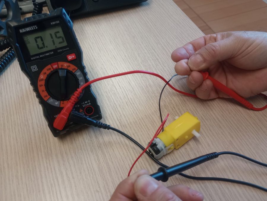
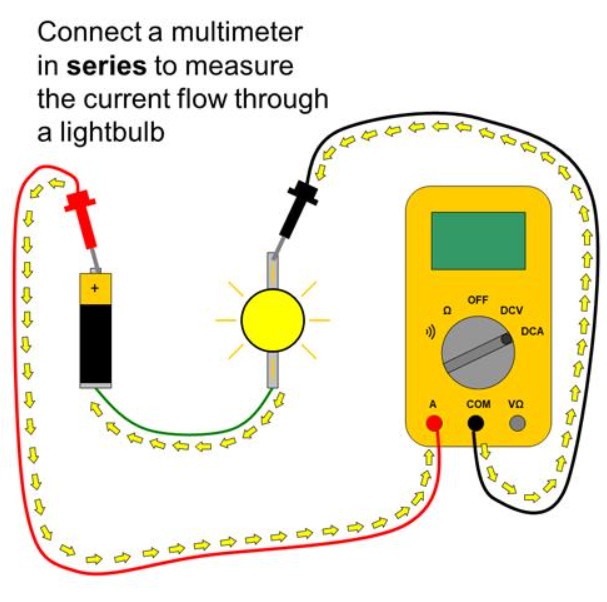
- We connected the multimeter in series with the actuator to measure current.
- We repited the experiment with other devices
- We compared the values during different states, such as idle and active operation.
- We calculated or estimated the power consumption using the formula P = V × I and is 0,77 W.
Important Note
When measuring current with a multimeter, it is very important to connect it correctly and to use the appropriate measurement range, because a wrong connection can damage the multimeter fuse or the circuit.
Measured Results
- Supply voltage: 5,11V
- Current consumption in idle state: 0 A
- Current consumption in active state: 150 mA
- Estimated power consumption: 0,77 W
What I Learned from the Group Assignment
- Output devices can consume much more current than a microcontroller pin can safely provide.
- It is essential to know the electrical requirements before connecting an actuator.
- The multimeter is enough for basic current measurements, but dynamic behaviour may require an oscilloscope.
- Power consumption affects component selection, power supply design, and driver stage design.
This group assignment helped me understand that controlling an output device is not only about making it move, light up, or sound. It is also about making sure the circuit can power it safely and reliably.
Individual Assignment – Add an Output Device to a Microcontroller Board and Program It
Yu can find the resouces of this board in my assignement 6
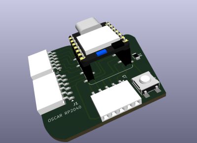
Week6For the individual assignment I added an output device to a microcontroller board that I had designed previously and programmed it to do something useful.
Following the recommendation from the instructors, I tried to choose an actuator that could also be useful for my final project.
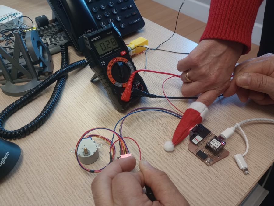
In this case I used a stteper and servo motor connected to a Xiao RP2040. The objective was to control the device through code and verify that the board could drive it correctly.
- Actuator: Motor stepper
- Board: Xiao RP2040
- Signal type: DIGITAL
- Main function: Main velocity
- Actuator: Sevo motor
- Board: Xiao RP2040
- Signal type: PWM
- Main function: Main control
The measurements previously carried out in the group setting, which I have documented earlier, were performed using this equipment.
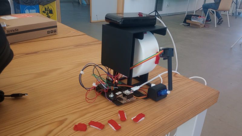
Espiral 2 – Output Module / Interactive Toy
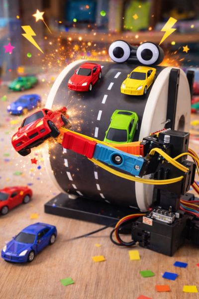
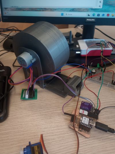
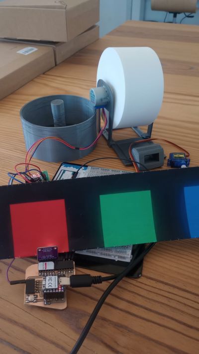
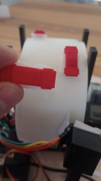
In this spiral I designed and programmed an interactive toy that combines a stepper motor, a servo motor, and a color sensor.
The system consists of a rotating cylinder driven by a stepper motor. On the surface of the cylinder I drew cars in different colors (red and green). A servo motor moves the color sensor, allowing it to scan the surface.
The game consists of avoiding the red cars, as hitting one will end the game, and collecting the green flags, which will make the player move faster.The button makes the servo (the car) move to the right, while if it is not pressed, the car moves to the left.
The behavior of the system is controlled by both the detected colors and a user button, creating a simple interactive game.
Game Logic
- Blue color: starts the motor (game begins).
- Green color: increases the speed of the motor.
- Red color: stops the motor (end of the game).
- Button (D7): moves the servo to the right.
- If the button is not pressed, the servo automatically moves slowly to the left.
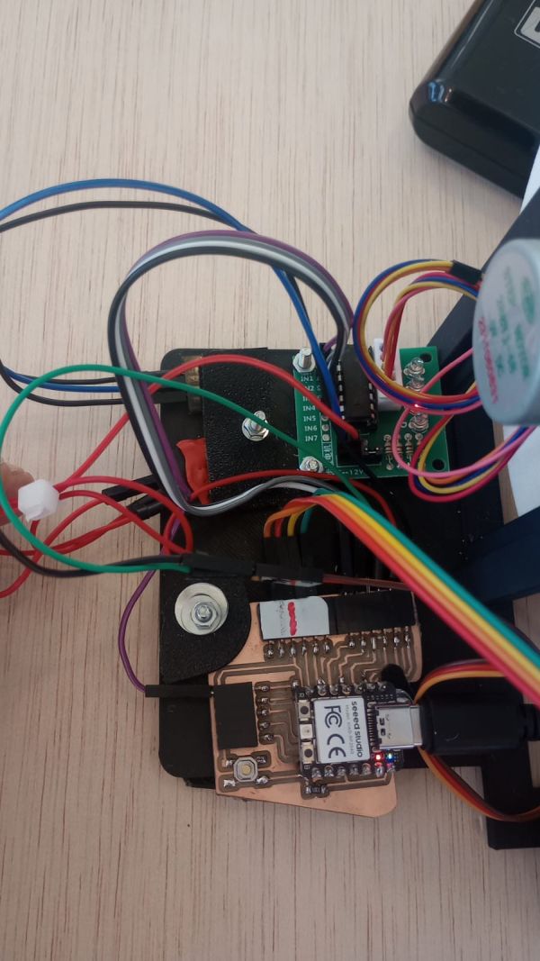
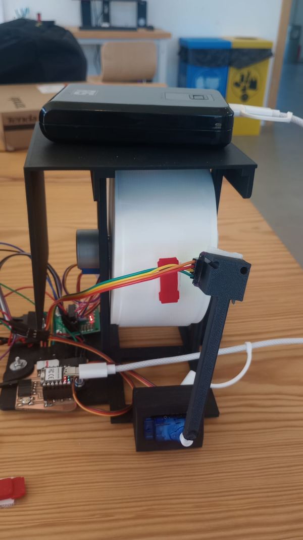
System Design and Architecture
The system integrates multiple components:
- Stepper motor (28BYJ-48) to rotate the cylinder.
- Servo motor to move the color sensor.
- TCS34725 color sensor to detect the colors on the surface.
- Push button for user interaction.
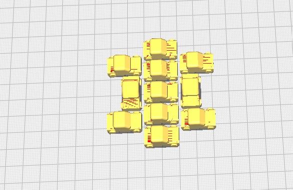
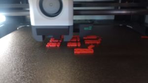
- 3D Cilinder Road simulation.
- 3D Soports for soport everythings
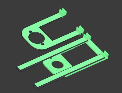
Lateral pieces

cilinder
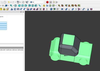
Car
The main challenge was coordinating motion and sensing in real time without blocking
the system. This required a non-blocking approach using timing with millis().
Design Considerations
- Separate control of motor speed and movement.
- Servo position control with both manual and automatic behavior.
- Reliable color detection with threshold margins.
- Debounced button input for stable user interaction.
- Made a property desing in 3D and print it
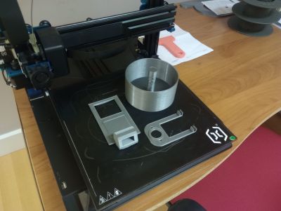
First desing for test
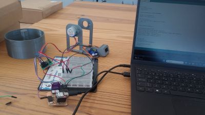
testing motors
Color sensor test
There are mechanical robustness issues in the design, so I redesigned it from scratch.
Interfacing the System
The system connects multiple actuators and sensors to the microcontroller:
- Stepper motor: controlled via ULN2003 driver.
- Servo motor: controlled using PWM signal.
- Color sensor: connected via I2C communication.
- Button: connected using internal pull-down configuration.
Electrical Connections
- Stepper motor connected to digital pins through driver.
- Servo signal connected to a PWM-capable pin.
- I2C lines used for the color sensor.
- Button connected between 3.3V and input pin (pull-down logic).
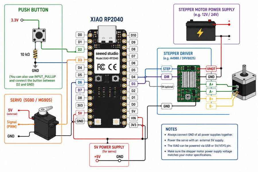
this is the wiring diagram
Code and System Behaviour
The program controls the interaction between motion and sensing. It uses non-blocking timing to allow the motor, servo, and sensor to operate simultaneously.
Main Features of the Code
- The stepper motor runs continuously when enabled.
- The servo moves right when the button is pressed.
- The servo automatically moves left over time when idle.
- The color sensor determines the game state.
- Motor speed increases dynamically when detecting green.
Game Behaviour
- Blue → start movement
- Green → accelerate
- Red → stop
Arduino Game Code Show code
#include
#include "Adafruit_TCS34725.h"
#include
#include

Servo miServo;

// =========================
// SENSOR COLOR
// =========================
Adafruit_TCS34725 tcs = Adafruit_TCS34725(
  TCS34725_INTEGRATIONTIME_50MS,
  TCS34725_GAIN_4X
);

// =========================
// MOTOR
// =========================
const int stepsPerRevolution = 2048;
Stepper motor(stepsPerRevolution, D6, D2, D1, D3);

// =========================
// BOTON UNICO
// =========================
const int pinBtnServo = D7;   // PULLDOWN

// =========================
// SERVO
// =========================
const int pinServo = D0;
int anguloServo = 90;

// límites de giro
const int anguloMinServo = 27;
const int anguloMaxServo = 150;

// temporización servo
unsigned long ultimoMovimientoDerecha = 0;
unsigned long ultimoMovimientoIzquierda = 0;
const unsigned long intervaloServoDerecha = 1000;
const unsigned long intervaloServoIzquierda = 1000;

// =========================
// COLOR
// =========================
const int brilloMinimo = 100;
const int margenColor = 60;

// rojo más estricto
const int margenRojo = 120;          // más alto que el margen general
const int rojoMinimo = 180;          // valor mínimo absoluto
const float proporcionRojo = 0.30;   // el rojo debe ser casi la mitad del total RGB

// confirmación en varias lecturas
int contadorRojo = 0;
const int rojoConfirmaciones = 3;

// =========================
// MOTOR CONTROL
// =========================
bool motorHabilitado = false;
int nivelVelocidad = 1;
const int nivelMaxVelocidad = 20;
const int rpmBase = 7;
unsigned long ultimoPaso = 0;
unsigned long intervaloPaso = 20;

// =========================
// DEBOUNCE BOTON D7
// =========================
const unsigned long debounceDelay = 50;
bool ultimaLecturaBoton = LOW;
bool estadoEstableBoton = LOW;
unsigned long ultimoCambioBoton = 0;

// =========================
// FUNCIONES
// =========================
void actualizarVelocidadMotor() {
  int rpmActual = rpmBase * nivelVelocidad;
  motor.setSpeed(rpmActual);

  intervaloPaso = 20 / nivelVelocidad;
  if (intervaloPaso < 2) intervaloPaso = 2;

  Serial.print("Nivel velocidad: ");
  Serial.print(nivelVelocidad);
  Serial.print(" | RPM: ");
  Serial.println(rpmActual);
}

void leerBotonServo() {
  bool lectura = digitalRead(pinBtnServo);

  if (lectura != ultimaLecturaBoton) {
    ultimoCambioBoton = millis();
    ultimaLecturaBoton = lectura;
  }

  if ((millis() - ultimoCambioBoton) > debounceDelay) {
    estadoEstableBoton = lectura;
  }
}

void moverServoDerechaSiPulsado() {
  if (estadoEstableBoton == HIGH) {
    if (millis() - ultimoMovimientoDerecha >= intervaloServoDerecha) {
      ultimoMovimientoDerecha = millis();

      if (anguloServo < anguloMaxServo) {
        anguloServo += 15;
        if (anguloServo > anguloMaxServo) anguloServo = anguloMaxServo;

        miServo.write(anguloServo);

        Serial.print("Servo derecha -> angulo: ");
        Serial.println(anguloServo);
      }
    }
  }
}

void moverServoAutomaticoIzquierda() {
  if (estadoEstableBoton == LOW) {
    if (millis() - ultimoMovimientoIzquierda >= intervaloServoIzquierda) {
      ultimoMovimientoIzquierda = millis();

      if (anguloServo > anguloMinServo) {
        anguloServo -= 15;
        if (anguloServo < anguloMinServo) anguloServo = anguloMinServo;

        miServo.write(anguloServo);

        Serial.print("Servo izquierda -> angulo: ");
        Serial.println(anguloServo);
      }
    }
  }
}

void leerColorYControlMotor() {
  static unsigned long ultimoColor = 0;

  if (millis() - ultimoColor < 150) return;
  ultimoColor = millis();

  uint16_t r, g, b, c;
  tcs.getRawData(&r, &g, &b, &c);

  if (c < brilloMinimo) {
    contadorRojo = 0;
    return;
  }

  float sumaRGB = r + g + b;
  float ratioRojo = 0.0;

  if (sumaRGB > 0) {
    ratioRojo = (float)r / sumaRGB;
  }

  Serial.print("R: ");
  Serial.print(r);
  Serial.print(" G: ");
  Serial.print(g);
  Serial.print(" B: ");
  Serial.print(b);
  Serial.print(" C: ");
  Serial.print(c);
  Serial.print(" RatioR: ");
  Serial.println(ratioRojo, 3);

  // ROJO = parar (más estricto)
  if ((r > rojoMinimo) &&
      (r > g + margenRojo) &&
      (r > b + margenRojo) &&
      (ratioRojo > proporcionRojo)) {

    contadorRojo++;

    Serial.print("Confirmacion rojo: ");
    Serial.println(contadorRojo);

    if (contadorRojo >= rojoConfirmaciones) {
      if (motorHabilitado) {
        motorHabilitado = false;
        Serial.println("ROJO -> MOTOR PARADO");
      }
      contadorRojo = rojoConfirmaciones;
    }
  }
  else {
    contadorRojo = 0;

    // VERDE = acelerar
    if ((g > r + margenColor) && (g > b + margenColor)) {
      nivelVelocidad++;
      if (nivelVelocidad > nivelMaxVelocidad) {
        nivelVelocidad = nivelMaxVelocidad;
      }
      actualizarVelocidadMotor();
      Serial.println("VERDE -> ACELERA");
      delay(300);
    }
    // AZUL = arrancar
    else if ((b > r + margenColor) && (b > g + margenColor)) {
      if (!motorHabilitado) {
        motorHabilitado = true;
        Serial.println("AZUL -> MOTOR EN MARCHA");
      }
    }
  }
}

void moverMotor() {
  if (!motorHabilitado) return;

  if (millis() - ultimoPaso >= intervaloPaso) {
    ultimoPaso = millis();
    motor.step(-1);   // giro inverso
  }
}

void setup() {
  Serial.begin(115200);
  delay(2000);

  pinMode(pinBtnServo, INPUT_PULLDOWN);

  miServo.attach(pinServo);
  miServo.write(anguloServo);

  if (!tcs.begin()) {
    Serial.println("Error: TCS34725 not found");
    while (1);
  }

  actualizarVelocidadMotor();

  Serial.println("Sistema ON");
  Serial.println("D7 pulsado = servo derecha");
  Serial.println("D7 suelto = servo izquierda");
  Serial.println("ROJO = parar motor");
  Serial.println("VERDE = acelerar motor");
  Serial.println("AZUL = arrancar motor");
  Serial.print("Angulo inicial servo: ");
  Serial.println(anguloServo);
}

void loop() {
  leerBotonServo();
  moverServoDerechaSiPulsado();
  moverServoAutomaticoIzquierda();

  leerColorYControlMotor();
  moverMotor();
}
Results
The final system works as an interactive toy where motion and sensing are combined into a simple game.
- The cylinder rotates smoothly using the stepper motor.
- The servo successfully scans the surface with controlled motion.
- The system reacts correctly to color detection.
- The interaction between user input and automatic behavior works reliably.
The project demonstrates how multiple outputs and inputs can be integrated into a single interactive system.
Problems and Fixes
Problem 1 – Button Input Issues
- Problem: Some pins did not respond correctly using pull-down configuration.
- Fix: Changed input strategy and simplified interaction using a single button.
Problem 2 – Servo Power
- Problem: The servo did not move reliably.
- Fix: Ensured proper external power supply and common ground.
Problem 3 – Blocking Code
- Problem: Using delays blocked the system.
- Fix: Replaced delays with
millis()for smooth multitasking.
Problem 3 – Blocking Code
- Problem: Using delays blocked the system.
- Fix: Replaced delays with
millis()for smooth multitasking.
Problem 4 – Servo Vibration
- Problem: The servo arm had unwanted vibration at the end position.
- Fix: Added an elastic band to stabilize the final position and reduce mechanical oscillations.
These problems helped me understand the importance of timing, power management, and proper input configuration in embedded systems.
Design Files, Source Code and Hero Shot
Design Files
Summary and Reflection

This week helped me understand the complete workflow of output devices, from measuring power consumption to designing a board, connecting an actuator, and controlling it through code.
One of the most important things I learned is that actuators are very different from sensors. In many cases, they require more current, more careful power management, and a better understanding of the electrical requirements of the circuit.
The group assignment helped me understand the importance of measuring current and power, while the individual assignment helped me understand how to drive an actuator in practice.
It was also quite labor-intensive to fine-tune all the parameters of the system to make the game fully functional. Due to the limited time available, I couldn’t afford mistakes, especially considering the long 3D printing times, which made each iteration slow and critical.
This week is especially useful for my future work because output devices are essential for creating interactive systems and for the development of my final project.