Week 16 – System Integration
This week is focused on System Integration. The goal was to design and document how all the parts of my final project come together as a complete system.
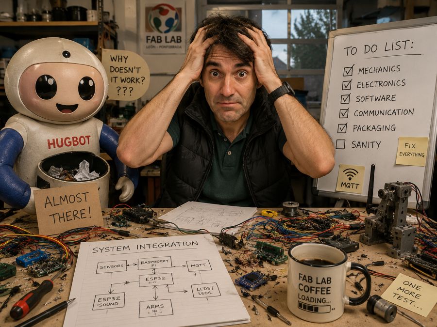
My final project is Hugbot, an interactive robot that gives a hug as a reward when a child deposits trash in a dedicated container. The project combines mechanical design, electronics, sensors, actuators, communication, programming and packaging into one finished product.
On this page I document:
- The system integration plan for my final project.
- The main subsystems of Hugbot.
- The physical packaging of the electronics and mechanisms.
- The integration of sensors, actuators and controllers.
- The communication between the Raspberry Pi and ESP32 boards.
- The design decisions to make the robot look like a finished product.
- The problems found during integration and how I plan to solve them.
- The link between this assignment and my final project documentation.
Assignment and Learning Outcomes
The weekly assignment is:
- Design and document the system integration for the final project.
Learning Outcomes
- Define and apply system integration to my final project.
- Plan how all mechanical, electronic and software parts work together.
- Document the system with diagrams, sketches and CAD references.
- Apply packaging methods so that every component has its own place.
- Design the final project to look like a finished product.
Checklist
- Made a plan for system integration for my final project.
- Documented the plan with sketches, diagrams and CAD references.
- Implemented packaging methods for electronics, wiring and mechanical parts.
- Designed the final project to look like a finished product.
- Documented the system integration of my final project.
- Linked this documentation from my final project page.
Final Project Overview – Hugbot
Hugbot is a friendly interactive robot designed to attract children to the Fab Lab and promote environmental awareness. The idea is simple: when a child brings trash and deposits it in the robot container, the system detects the action and rewards the child with lights, sound and a hug.
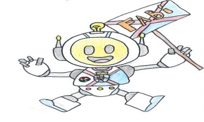
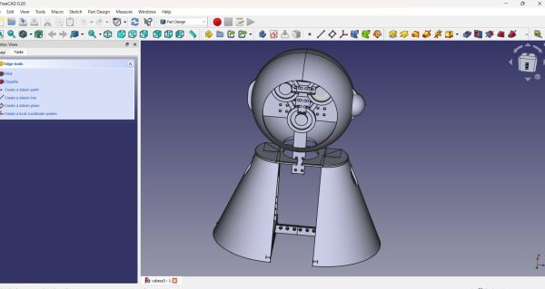
Reference image used as the basis for the new robot design.
The project has evolved into a robot inspired by the Fab Lab Ponferrada mascot. This decision is important for system integration because the electronics, arms, sensors and internal structure must fit inside a specific physical shape, not just inside a simple rectangular box.
The final robot must be safe, friendly, robust and easy to understand. For this reason, the integration is not only technical. It also includes the external appearance, the position of the arms, the location of the sensors, cable routing, accessibility for maintenance and user safety.
Link to my final project page: Hugbot – Final Project
SCHEDULE
🤖 Fab Academy Robot Schedule – System Integration Plan
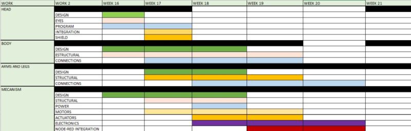
- Design
- Eyes
- Program
- Integration
- Shield
- Design
- Structural parts
- Connections
- Design
- Structural parts
- Connections
- Design
- Structural parts
- Power system
- Motors
- Actuators
- Electronics
- Node-RED integration
System Integration Plan
The system integration plan defines how the different parts of Hugbot are connected physically and logically. I divided the project into several subsystems so that each part can be designed, tested and then integrated into the complete robot.
Main Subsystems
| Subsystem | Function | Main Components |
|---|---|---|
| Mechanical structure | Supports the complete robot and gives it the final shape | Body, head, base, arms, internal supports |
| Trash detection | Detects when trash has been deposited | Sensor, bin, wiring, input board |
| Perception system | Detects nearby people and starts interaction | Raspberry Pi, camera, proximity sensor, OpenCV |
| Arm movement | Moves the arms to perform the hug action | ESP32 boards, motors or servos, gears, joints |
| Feedback system | Gives visual and sound feedback to the user | LEDs, speaker or buzzer |
| Communication | Coordinates the different controllers | MQTT, WiFi, Raspberry Pi, ESP32 boards |
| Packaging | Holds electronics and wiring safely inside the robot | Mounts, connectors, cable paths, covers |
Integration Strategy
- Design the external robot shape based on the mascot.
- Define the internal volume available for electronics and mechanisms.
- Place the Raspberry Pi in an accessible central position.
- Place one ESP32 module close to each arm to reduce long motor wires.
- Route power cables separately from signal cables when possible.
- Use connectors to make the arms and panels removable.
- Test each subsystem separately before final assembly.
- Integrate the complete interaction sequence: detect trash, react, open arms and give feedback.
System Architecture
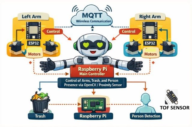
The architecture is based on a central controller and distributed arm controllers. The Raspberry Pi works as the main controller because it manages the camera, proximity detection and general behaviour of the robot. The arm movement is controlled by ESP32 boards, one for each arm.
Controller Distribution
- Raspberry Pi: main logic, OpenCV, proximity detection and MQTT coordination.
- ESP32 left arm: controls the left arm motor or servo.
- ESP32 right arm: controls the right arm motor or servo.
- Trash sensor: detects when the child deposits trash.
- LEDs and sound: provide feedback during the interaction.
I chose this distributed architecture because it makes the robot more modular. If one arm needs to be modified or repaired, I can work on that part without changing the whole system. It also reduces the number of long cables going from the central controller to the motors.
Communication Flow
- The robot waits in idle mode.
- The proximity sensor or camera detects a person near the robot.
- The robot invites the child to deposit trash.
- The trash sensor confirms that an object has been deposited.
- The Raspberry Pi publishes a command through MQTT.
- The ESP32 arm controllers receive the command.
- The arms move to perform the hug action.
- The LEDs and sound system give positive feedback.
- The robot returns to the initial safe position.
CAD and Physical Integration
The mechanical design is one of the most important parts of the integration. Hugbot is not only an electronic prototype: it must look like a finished product and be safe for children to interact with.
Mechanical Parts
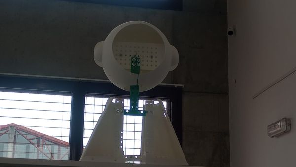
- Head: contains the face and gives personality to the robot.
- Body: contains the trash container and internal electronics.
- Arms: perform the hugging movement.
- Base: gives stability to the robot.
- Internal mounts: hold boards, sensors and power components.
- Covers: hide electronics and protect the user from moving parts.
Design Requirements
- The robot must be stable and not fall when children interact with it.
- The arms must move smoothly and safely.
- The electronics must be protected but accessible for maintenance.
- The trash container must be easy to empty.
- The external shape must be friendly and recognizable.
- The cables must not be visible from the outside.
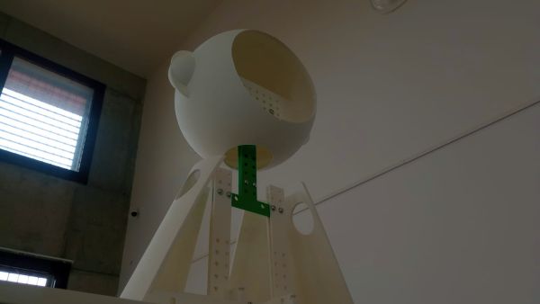
I used the CAD model to think about where each component should be placed. This helped me avoid a common problem in final projects: designing the outside first and then discovering that the electronics do not fit inside.
Packaging Methods
In this assignment, packaging means that every part has a defined place. The boards are not left hanging, the wires are not loose, and the components are mounted in a way that makes the prototype closer to a real finished product.
Electronics Packaging
- The Raspberry Pi will be mounted on an internal plate using screws and spacers.
- Each ESP32 board will be placed close to its corresponding arm.
- Power distribution will be fixed to the internal structure.
- Connectors will be used for motors, sensors and LED modules.
- Cables will be routed along the internal frame using clips or cable ties.
- The electronics area will be separated from the trash container.
Mechanical Packaging
- The arm mechanisms will be protected with covers.
- The moving parts will be located away from fingers as much as possible.
- The trash container will have a dedicated removable area.
- The head and body panels will hide the internal structure.
- Soft materials will be used in the hugging area.
Connectors and Maintenance
I plan to use connectors instead of soldering every wire permanently. This is important because the robot has several modules. If I need to remove an arm, replace a sensor or open the body, connectors make the process much easier and safer.
| Connection | Packaging Method | Reason |
|---|---|---|
| Motors / servos | Dedicated connectors near each arm | Easy removal and replacement |
| Sensors | Small connectors and labelled wires | Clear debugging and maintenance |
| Power | Fixed internal distribution | Safe and stable operation |
| LEDs | Removable connector | Allows replacement if damaged |
| Raspberry Pi | Screwed mount with access to ports | Easy programming and updates |
Finished Product Design
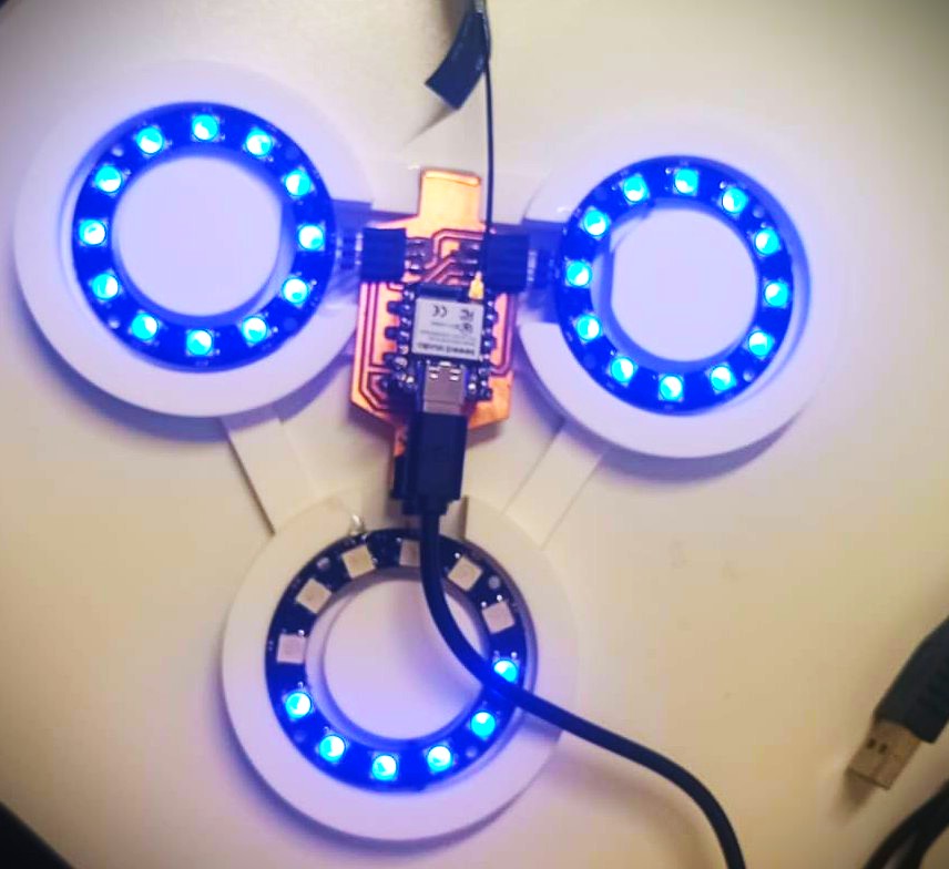
One of the requirements of this week is that the final project should look like a finished product. For me, this means that Hugbot must be more than a simple box with electronics inside. This is a example of the integration of ring leds for eyes
Design Decisions
- The robot shape is based on the Fab Lab Ponferrada mascot.
- The face and body are designed to look friendly for children.
- The electronics are hidden inside the structure.
- The trash container is integrated into the body.
- The arms are part of the character, not just external mechanisms.
- Soft areas are planned for the parts that touch the user during the hug.
- The robot will use lights and sound to make the interaction more understandable.
The goal is to make the robot feel like a character, not like a technical demonstration. Children should understand what to do without reading instructions, and the robot should communicate its state through movement, lights and sound.
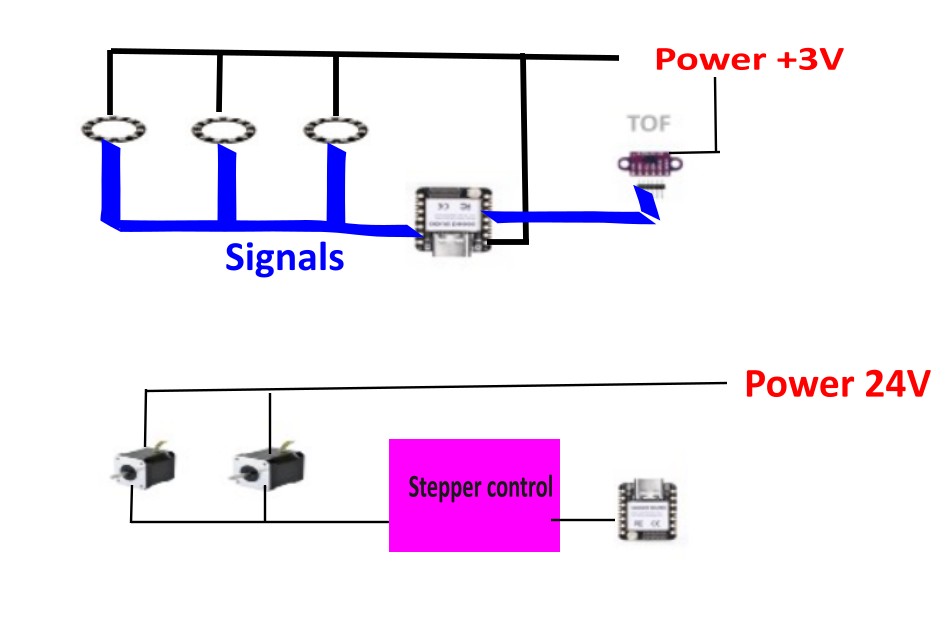
System Integration Diagram
The following diagram summarizes the complete integration of the project:
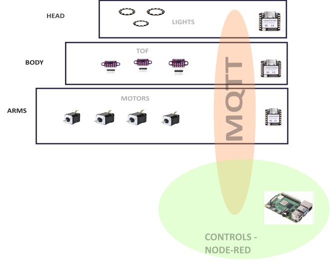
Integrated System Description
- The user interacts with the robot from the outside.
- The trash container receives the object.
- The trash sensor sends a signal to the control system.
- The Raspberry Pi decides the next state of the robot.
- MQTT messages are sent to the ESP32 arm controllers.
- The arms move using motors or servos.
- The LED and sound systems provide feedback.
- The robot returns to a safe idle position.
This diagram helps me check that all the parts are connected and that there are no missing elements between the user action and the robot response.
Integration Test Plan
Before testing the complete robot, I planned several smaller tests. This makes debugging easier because I can verify one subsystem at a time.
| Test | What I Check | Expected Result |
|---|---|---|
| Power test | Power supply, Raspberry Pi and ESP32 boards | All controllers turn on correctly |
| MQTT test | Communication between Raspberry Pi and ESP32 boards | Messages are received by the correct controller |
| Sensor test | Trash detection sensor | The system detects when trash is deposited |
| Arm test | Left and right arm movement | Both arms move smoothly and return to safe position |
| Feedback test | LEDs and sound | The robot gives clear visual and audio feedback |
| Full sequence test | Complete user interaction | The robot detects trash and performs the hug sequence |
Problems and Fixes
Problem 1 – Space inside the robot
- Problem: The mascot shape gives personality to the robot, but it also limits the internal space.
- Fix: I used the CAD model to reserve areas for the Raspberry Pi, ESP32 boards, sensors, wiring and mechanisms before final fabrication.
Problem 2 – Long motor wires
- Problem: Long wires from the central controller to the arms can make assembly and debugging difficult.
- Fix: I distributed the control using one ESP32 close to each arm.
Problem 3 – Safety during the hug
- Problem: The robot interacts physically with children, so the arms must be safe.
- Fix: I planned soft materials, limited movement range and a slow controlled hug sequence.
Problem 4 – Cable organization
- Problem: Many subsystems create many wires inside the robot.
- Fix: I planned cable paths, connectors and labelled wires for each subsystem.
Problem 5 – Making it look finished
- Problem: A functional prototype can still look unfinished if the electronics and mechanisms are visible.
- Fix: I designed covers, internal mounts and an external character shape based on the Fab Lab mascot.
Connection with My Final Project Page
This assignment is directly connected to my final project documentation. The system integration work described here will be linked from the final project page because it explains how the different parts of Hugbot become one complete product.
Final project link: Hugbot – Final Project
This documentation will also help me during the final weeks because it works as an assembly and integration checklist.
Summary and Reflection
This week helped me understand that system integration is not only connecting wires or combining code. It is the process of making all parts of the project work together inside a real physical object.
In Hugbot, the integration is especially important because the project combines mechanical movement, electronics, communication, sensors, actuators and user interaction. The robot must also be safe and friendly because it is designed for children.
The most important lesson for me was that packaging must be planned from the beginning. Every board, cable, sensor and actuator needs a dedicated place. A finished product is not only something that works, but something that can be assembled, maintained and used safely.
This assignment gave me a clearer roadmap for the final assembly of Hugbot. It also helped me identify possible problems before building the complete robot.
Credits and Acknowledgements
This documentation was developed as part of Fab Academy 2026.
- Project design and development: Oscar Cela Cobo.
- Fab Lab support: Fab Lab León / Fab Lab Ponferrada.
- System diagrams, English translation and programming support were assisted with ChatGPT.
- All design decisions, fabrication work, tests and final documentation were reviewed and adapted by me.