Computer-Aided Cutting
Group assignment:
- Do your lab's safety training
- Characterize your lasercutter's focus, power, speed, rate, kerf, joint clearance and types.
- Document your work to the group work page and reflect on your individual page what you learned.
Individual assignments
- Design, lasercut, and document a parametric construction kit, accounting for the lasercutter kerf.
- Cut something on the vinyl cutter.
You can see or Group Assignment documentation here.
Group Assignment – Laser Cutter Characterization
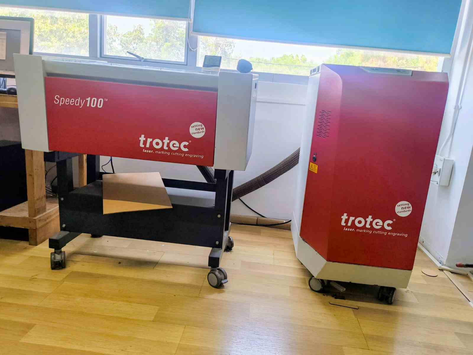
As part of our group assignment, we characterized the Trotec Speedy 100 laser cutter to understand how different machine parameters affect cutting performance and material behavior.
The objective was to analyze and document key laser parameters such as power, speed, frequency (rate), focus, kerf, and joint clearance. Understanding these parameters is essential for achieving precise cuts and designing accurate press-fit assemblies.
We studied how power controls the intensity of the laser beam, while speed determines how fast the laser head moves across the material. Higher power increases cutting depth, whereas higher speed reduces exposure time. Frequency (rate) affects how laser pulses interact with materials like wood and acrylic. Proper focus ensures that the laser beam is concentrated at the correct height for clean and efficient cutting.
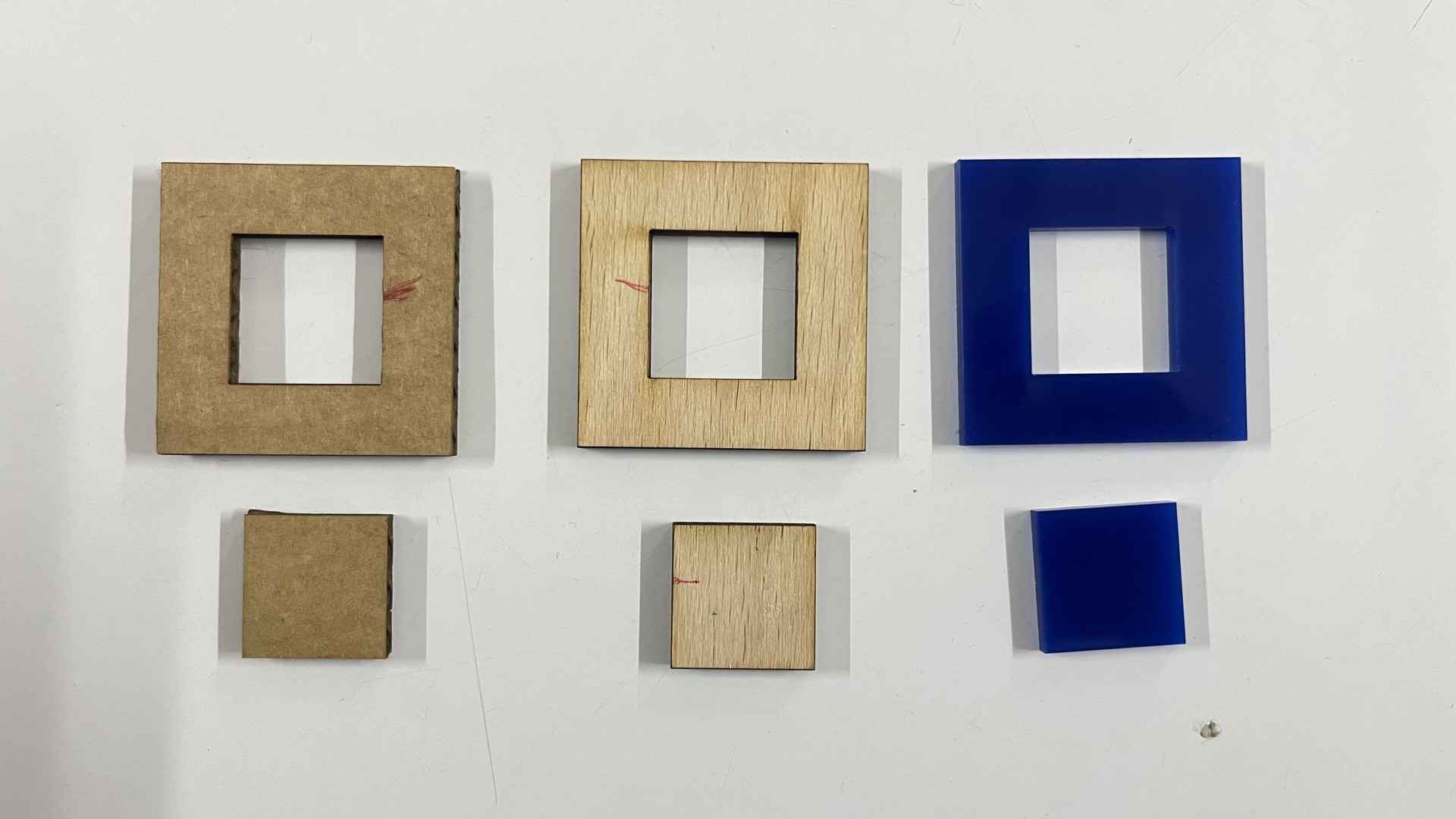
To determine kerf values, we performed kerf tests on three materials: cardboard, wood, and acrylic. We designed test pieces with multiple slots and cut them using predefined parameters. After cutting, we measured the difference between the designed dimensions and the actual dimensions to calculate the kerf for each material.
Kerf test pieces for cardboard, wood, and acrylic
Kerf comb test pieces for cardboard, wood, and acrylic
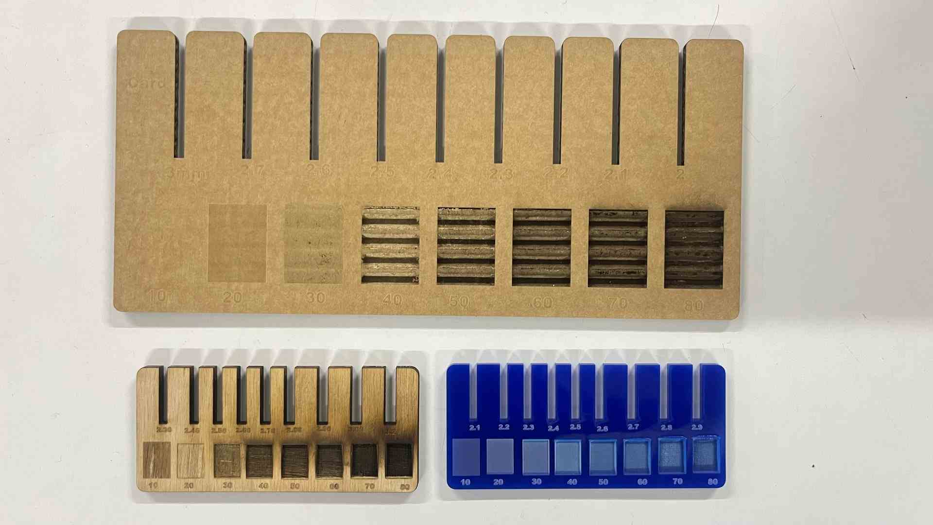
Based on these measurements, we calculated the required joint clearance for tight press-fit assemblies. We observed that kerf varies depending on material type, thickness, and laser settings. Acrylic produced cleaner edges, wood showed slight burn marks, and cardboard had the smallest resistance during cutting.
This assignment helped us understand how laser parameters interact and how small adjustments significantly impact fabrication accuracy. The results will guide future projects to ensure better tolerances and improved fit quality.
Vinyl Cutting
A vinyl cutter is an entry-level machine for making signs.
Computer-designed vector files with patterns and letters are directly cut on the roll of vinyl which is mounted and fed into the vinyl cutter through USB or serial cable.
In addition to sign business, vinyl cutters are commonly used for apparel decoration. To decorate apparel, a vector design needs to be cut in mirror image, weeded, and then heat applied using a commercial heat press or a hand iron for home use.
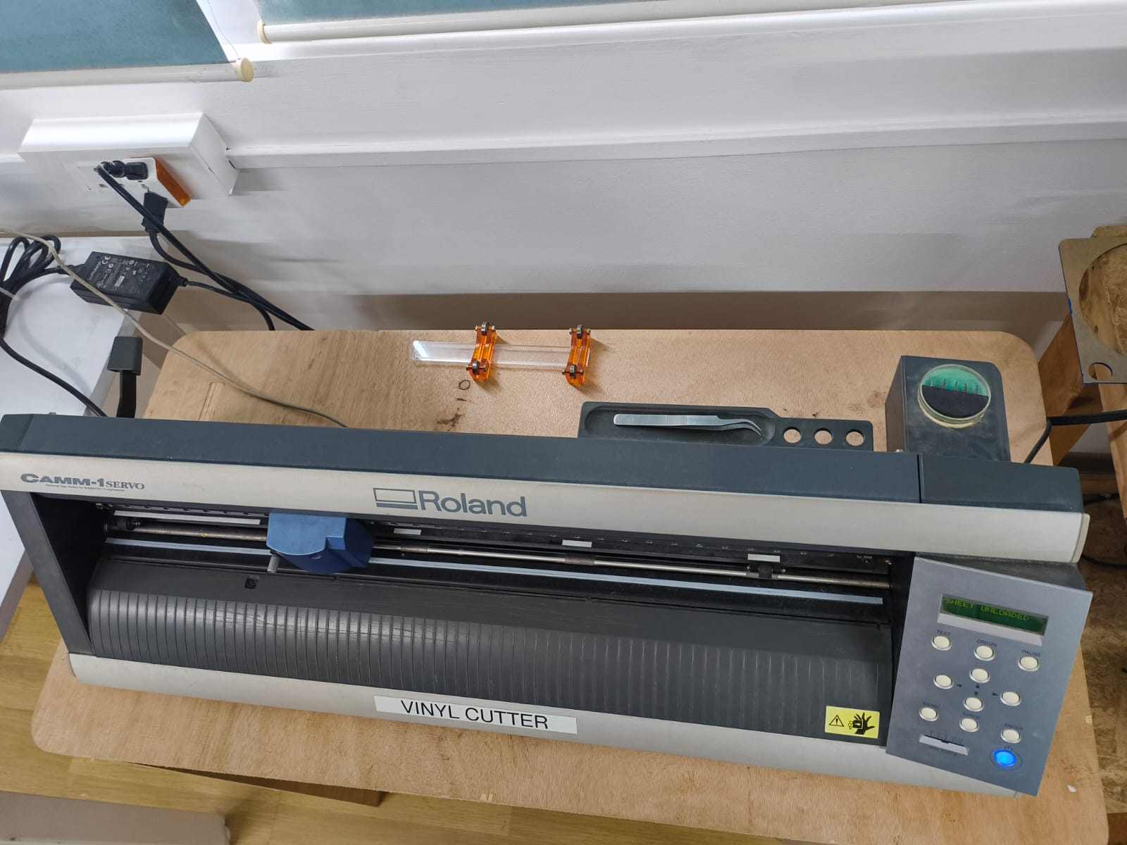
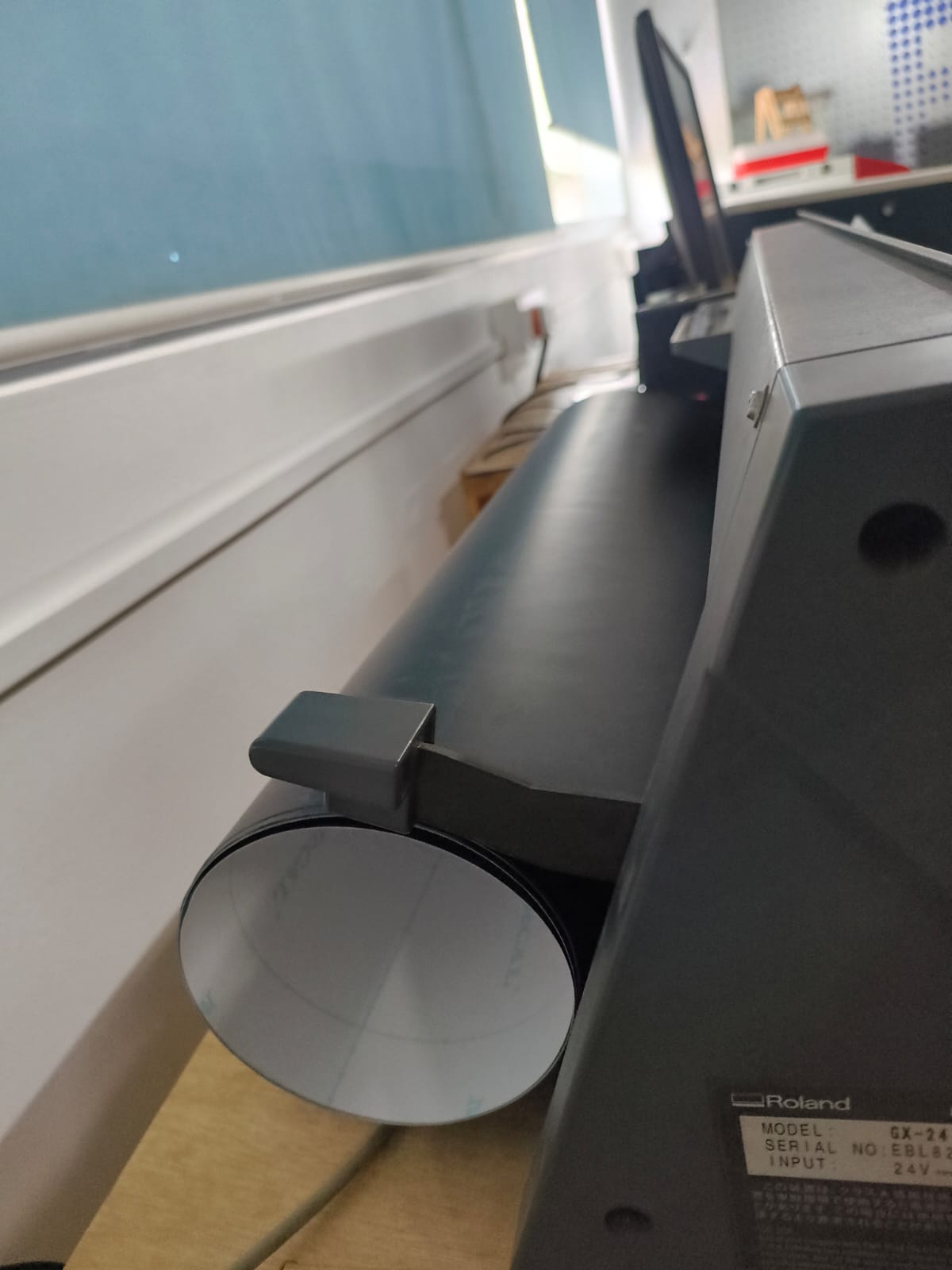
The Machine: Roland GX-24
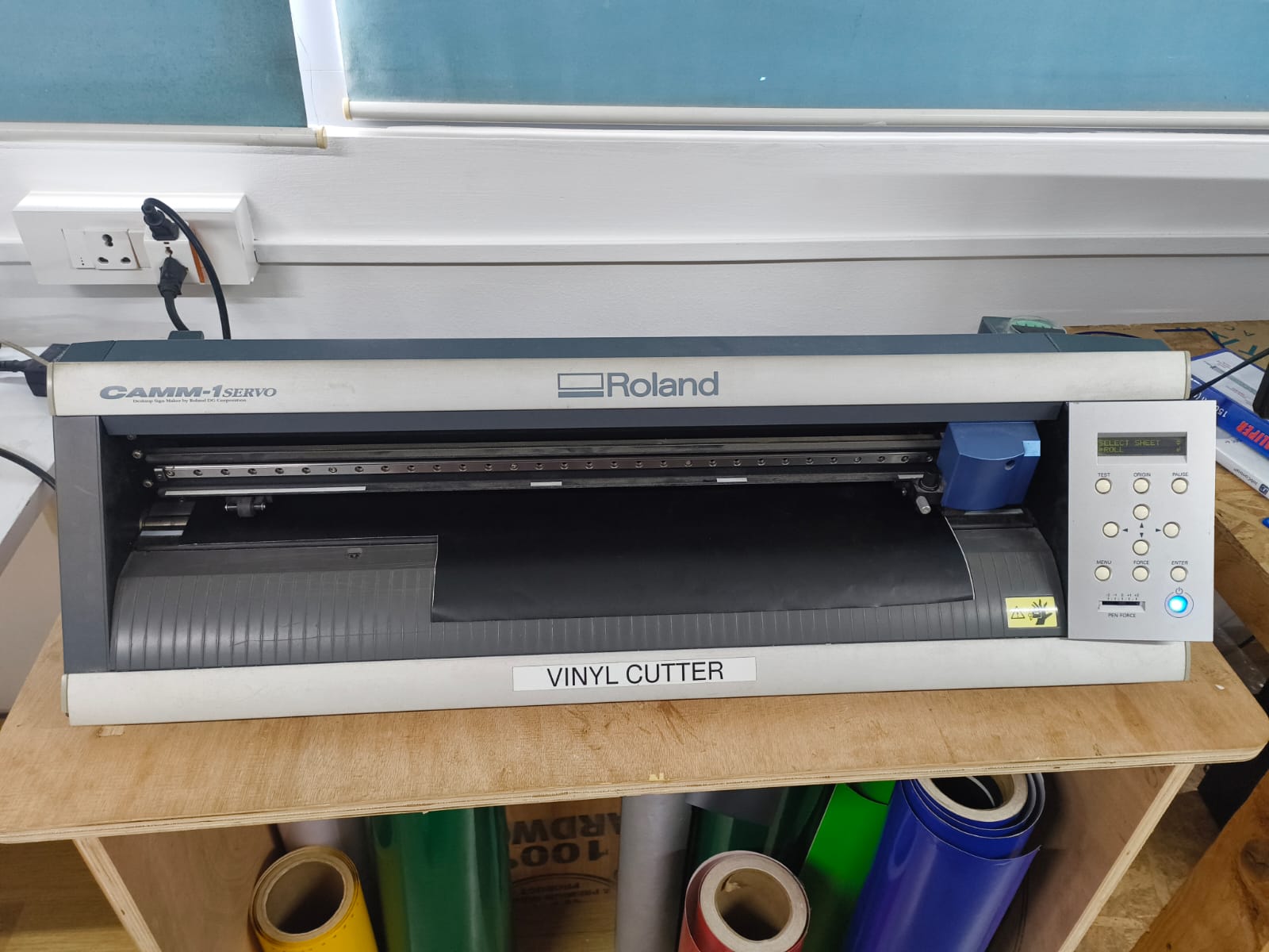
In our lab, we use the Roland GX-24 vinyl cutter, a servo-motor driven precision cutting machine designed for cutting vinyl, stickers, heat-transfer film, and other thin flexible materials.
The GX-24 operates as a passive blade cutter, meaning the blade is not motorized or actively controlled for rotation. Instead, it is mounted in a holder that allows it to freely swivel. As the machine moves along different directions, the blade automatically rotates and aligns itself with the direction of travel.
This passive drag-knife mechanism reduces mechanical complexity while still producing clean, accurate, and sharp cuts.
Because the machine is powered by servo motors, it provides:
- High positioning accuracy
- Smooth and controlled motion
- Precise corner cutting
- Consistent and repeatable results
These features make the Roland GX-24 fast, reliable, and well-suited for detailed vector designs such as logos, lettering, decals, and intricate patterns.
The Roland GX-24 uses a Passive Drag Knife system, which operates based on principles similar to a caster wheel on a shopping cart. The blade is housed in a swivel assembly and is not powered to rotate, but instead follows the direction of the carriage.
Vinyl Cutting Process
For the vinyl cutting assignment, I selected a Groot image (JPG) from Pinterest. Since vinyl cutters require vector files to follow continuous paths, the raster image had to be converted into a vector format before cutting.

The image was processed using Inkscape, an open-source vector graphics editor.
Step-by-Step Workflow
- Importing the Image
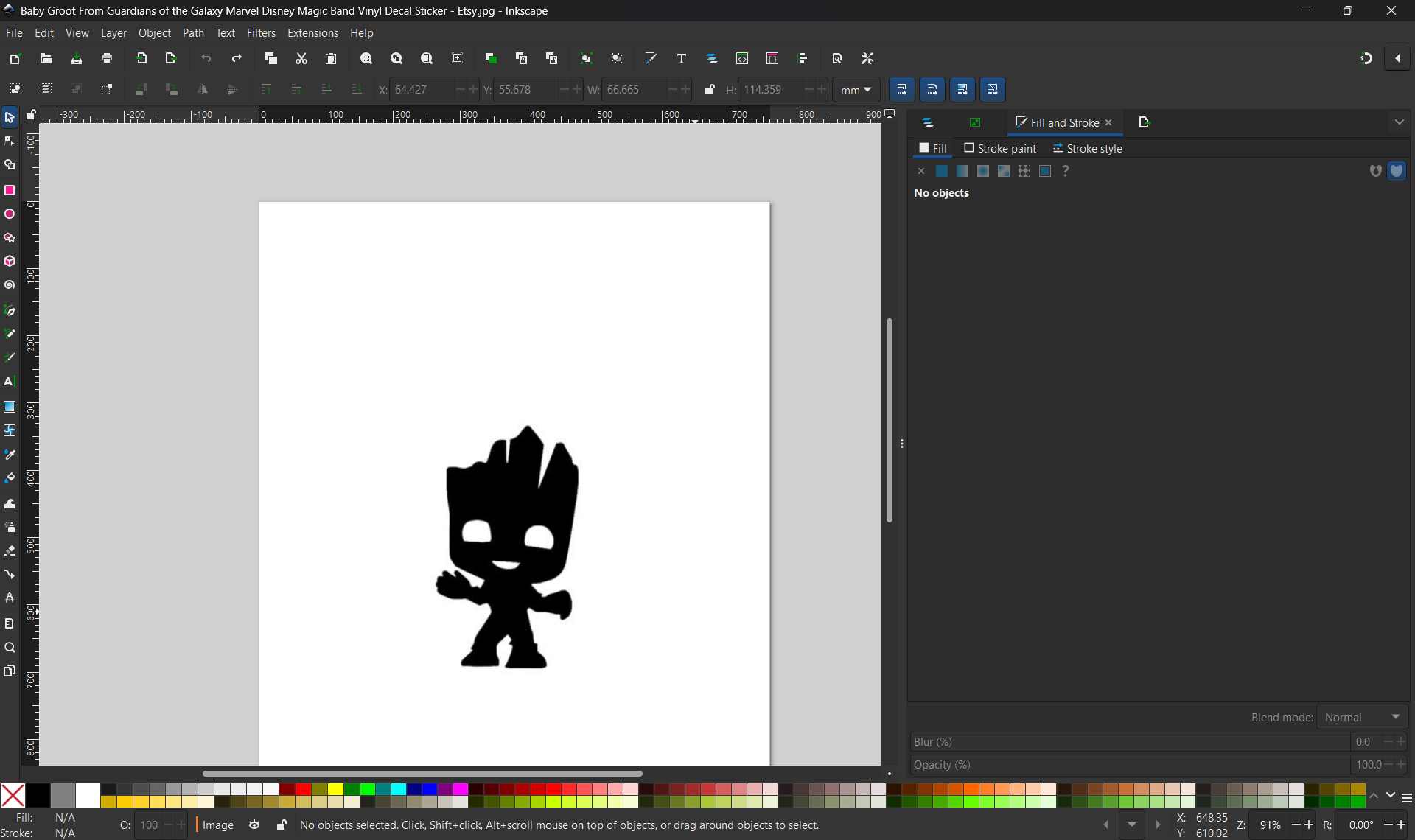
The Groot JPG image was opened in Inkscape using File → Open.
The image appeared as a raster bitmap and could not be directly used for vinyl cutting.
- Tracing the Bitmap
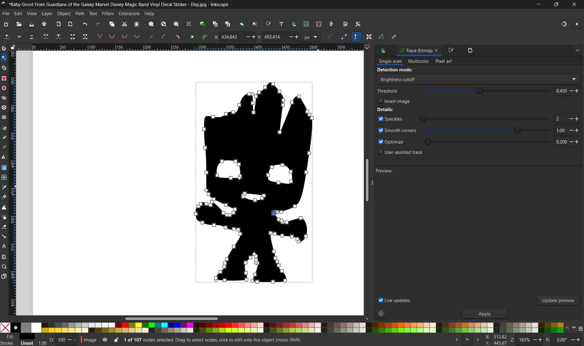
The image was selected and converted to vector format using Path → Trace Bitmap.
Threshold values were adjusted to obtain a solid black shape without internal lines or noise.
- Cleaning the Vector
After tracing, the original bitmap image was removed.
The vector paths were inspected and simplified where necessary.
Ensured that the design consisted of one continuous black silhouette, suitable for vinyl cutting.
- Exporting as SVG
The final vector design was saved using File → Export → SVG (.svg).
This SVG file was then ready to be imported into the vinyl cutter software.

Why SVG Is Required for Vinyl Cutting
Vinyl cutters operate by following vector paths, not pixels. Raster images such as JPG or PNG are made up of pixels and do not contain path information, which makes them unsuitable for direct cutting.
SVG (Scalable Vector Graphics) files:
- Store designs as mathematical paths
- Allow smooth, precise cutting
- Can be scaled to any size without losing quality
- Are universally supported by most vinyl cutter software
By converting the JPG image into an SVG file, the design became compatible with the vinyl cutter, ensuring accurate and clean cuts.
Vinyl Cutting Using Fab Modules
After converting the design into an SVG file, the vinyl cutting process was carried out using Fab Modules (modsproject.org). Fab Modules is a browser-based tool used to generate machine-specific toolpaths for digital fabrication machines.
Opening Fab Modules
Fab Modules was accessed through the browser at modsproject.org.
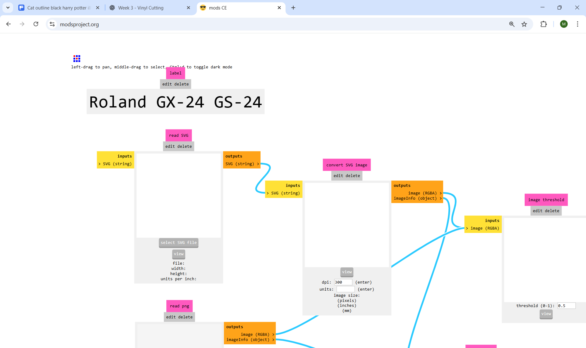
When Fab Modules is opened in the browser, it initially displays a blank workspace.

To access the main interface, you can right-click anywhere on the blank page.
This action opens the main menu, from which different programs, machines, and workflows can be selected.
Selecting the Program and Machine
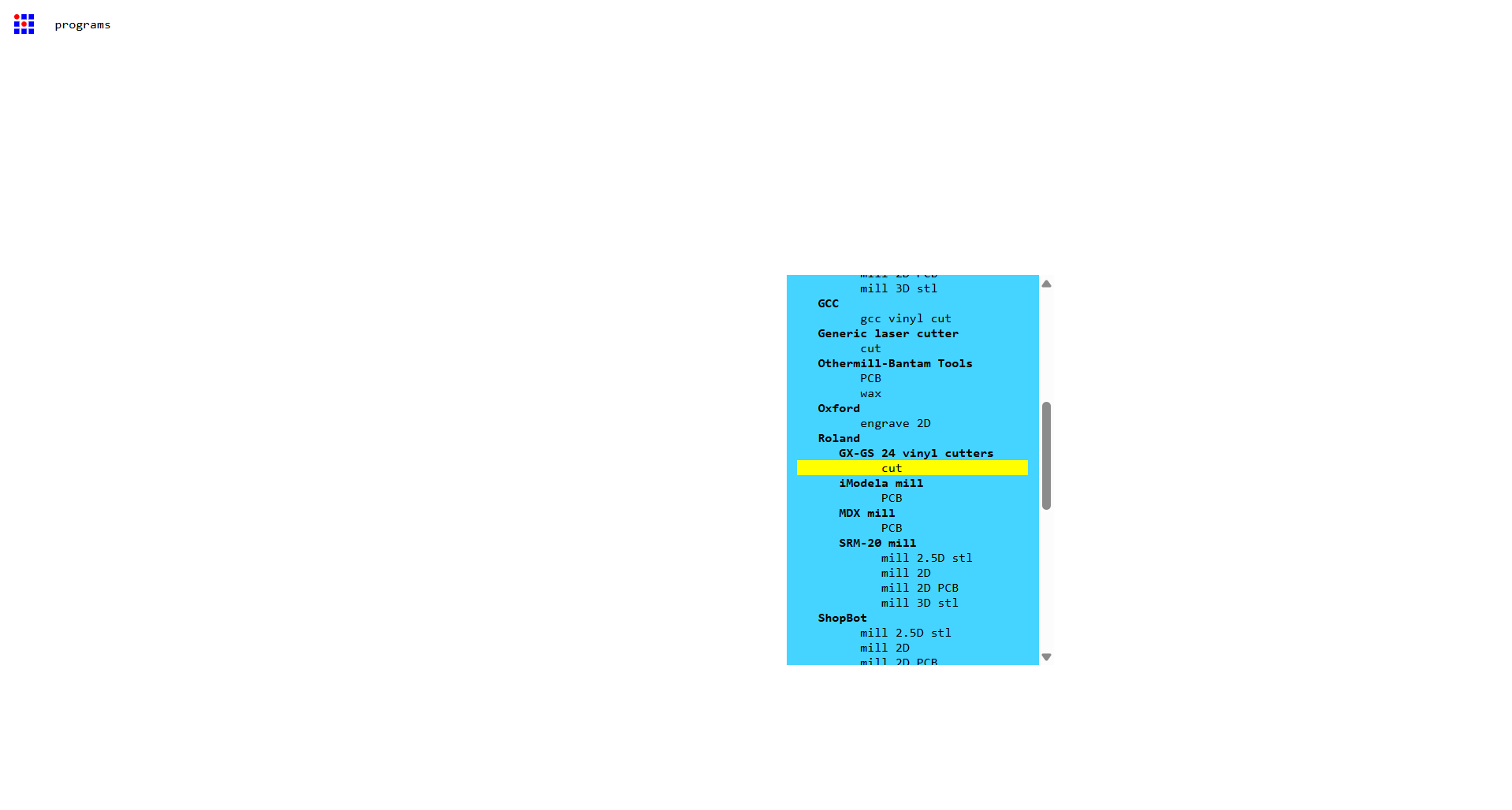
- From the main menu, Programs was selected.
- Under the list of available machines, Roland GX-24 / GS-24 vinyl cutter was chosen.
- The Cut operation was selected, which is specifically used for vinyl cutting.
This loads the predefined workflow for the Roland vinyl cutter.
Importing the Design File
To import the design file:
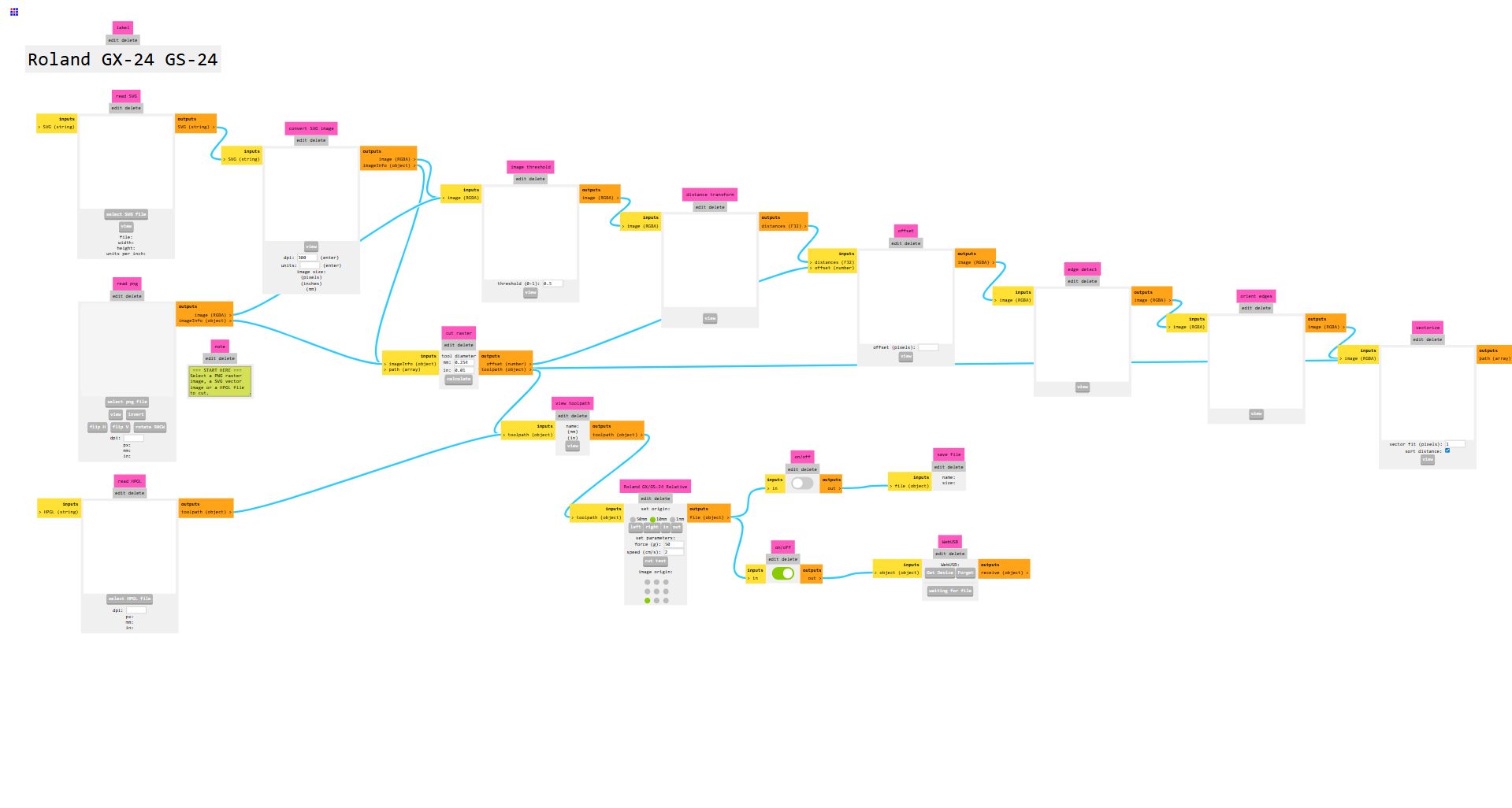
- Navigate to the first node on the left, labeled “read svg”.
- Click Select SVG file.
- Load the prepared vector file.
Fab Modules allows starting from either:
- an SVG vector file, or
- a PNG raster file, using the two input nodes on the far left.
In this case, an SVG file was used to preserve clean vector paths.
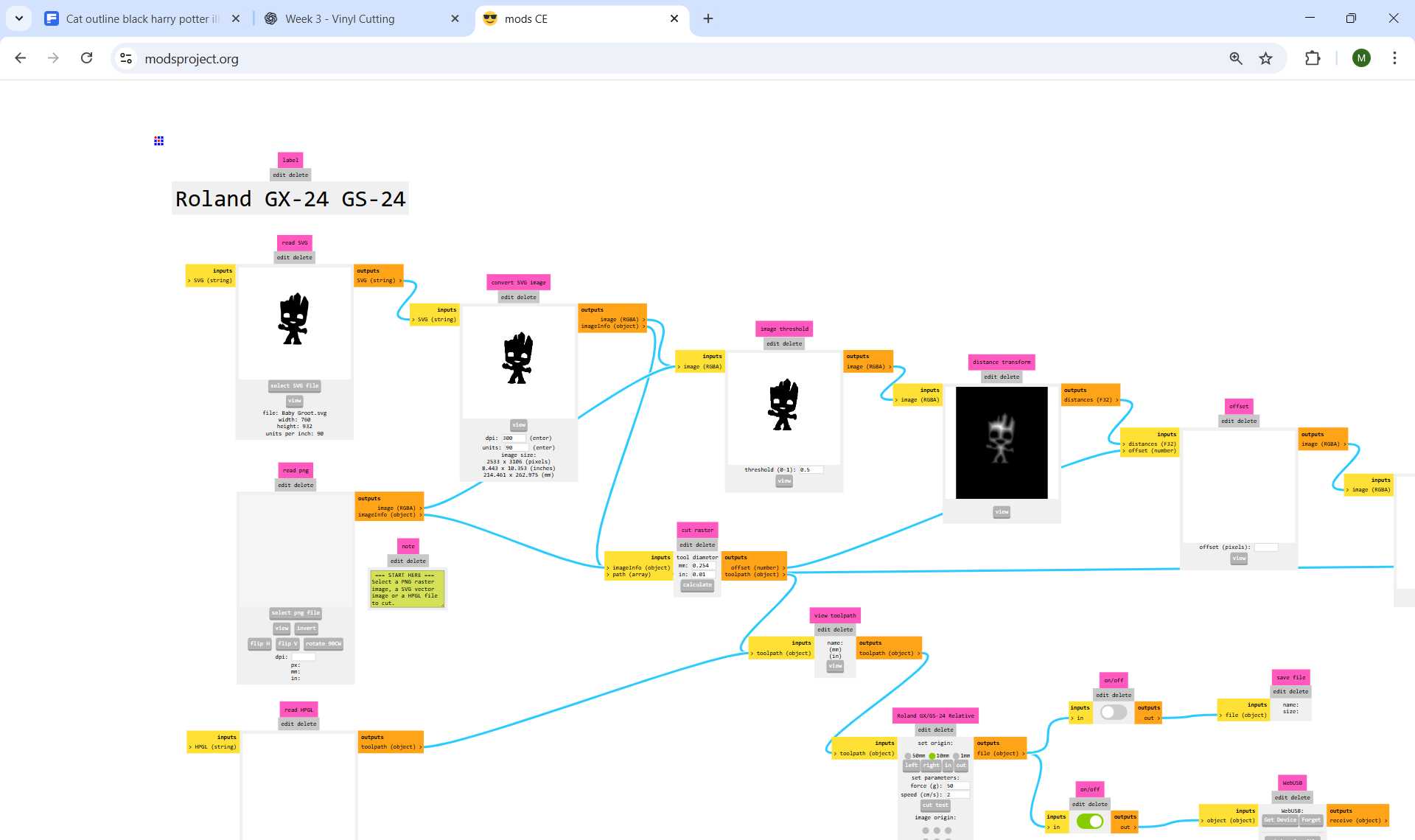
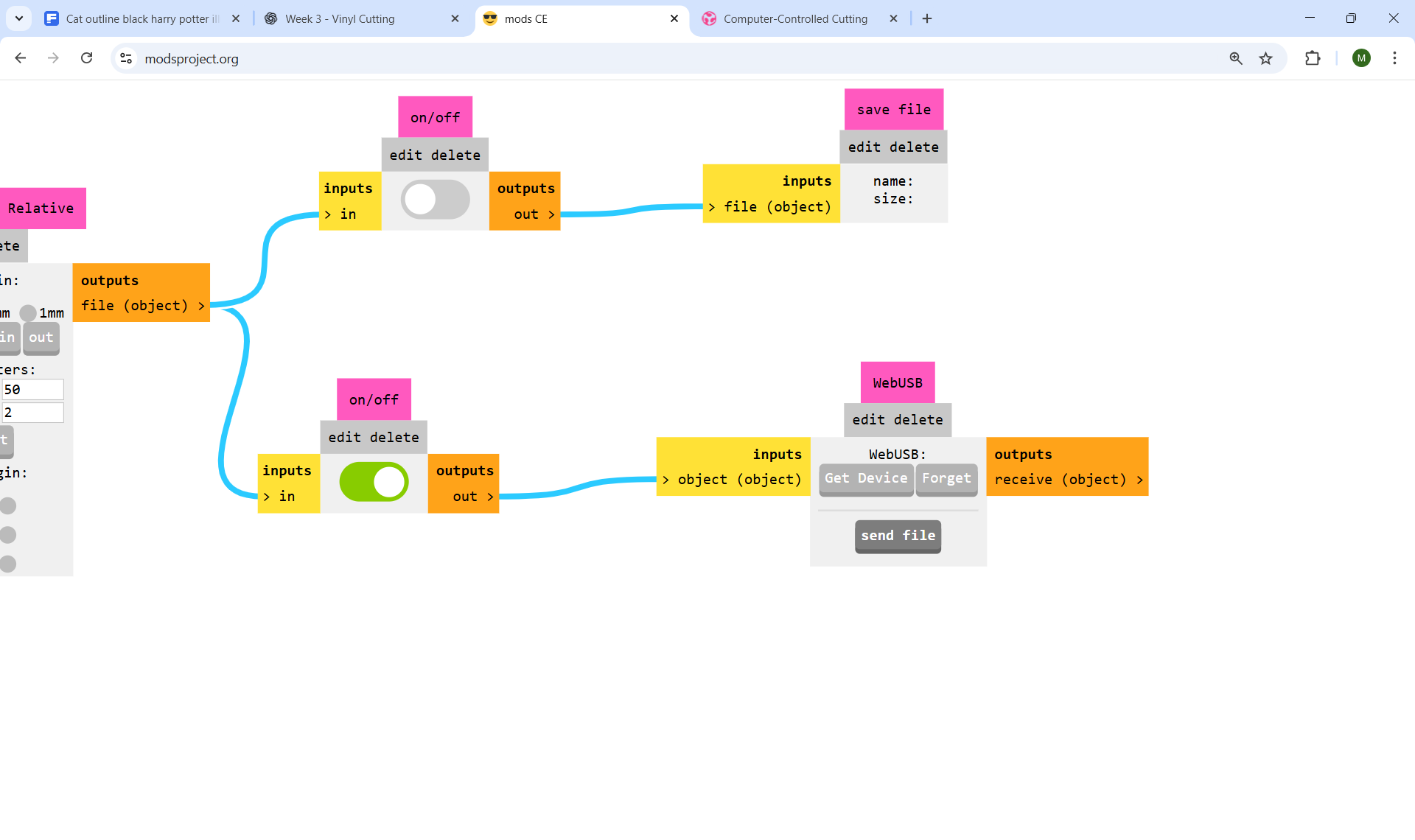
Once the file is loaded, the upper-right processing nodes are automatically populated.
Tool Setttings
After importing the file, only minimal parameter changes are required.
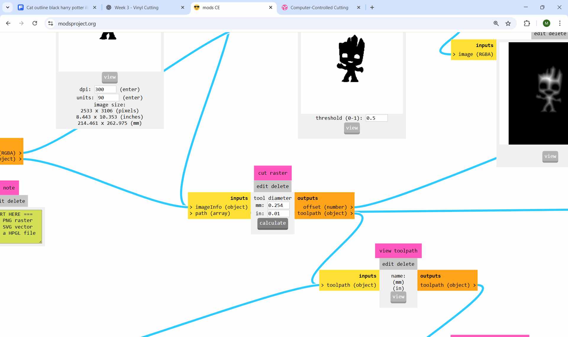
The tool diameter is already predefined in the cut raster node
- Tool diameter: 0.254 mm
Since the default value matches the vinyl cutter blade, no modification was needed.
The next step is to click Calculate in the cut raster node.
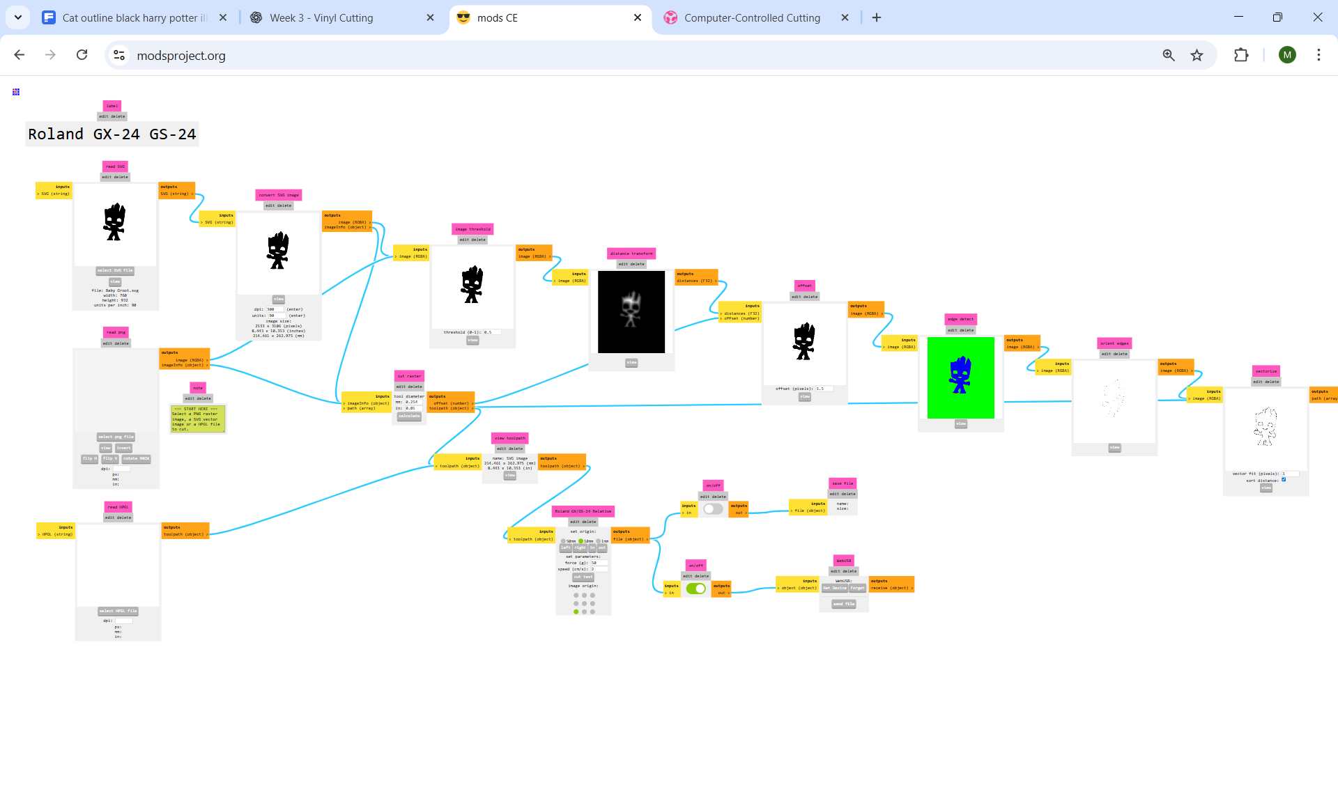
Visualizing the Cutting Path
After clicking Calculate:
- The cutting path is visualized in the preview window.
- The lower three nodes are automatically filled with processed images.
In the preview window
- Blue lines indicate cutting paths (blade down)
- Red lines indicate non-cutting movements (blade lifted)

Sending the File to the Vinyl Cutter
After verifying the toolpath preview, the cutting file was prepared for output.
Vinyl Cutter Machine Setup
The vinyl cutter was powered on using the main power button located at the bottom-right of the control panel.
Material Type Selection
The machine asks whether the material is:
- Roll
Used for continuous vinyl rolls. The machine measures only the width of the material.
- Piece
Used for individual sheets. The machine moves the material forward and backward to measure both the width and length accurately.
The forward and backward arrow buttons on the control panel are used to navigate between the options. Once the correct option is highlighted, the Enter button is pressed to confirm the selection.
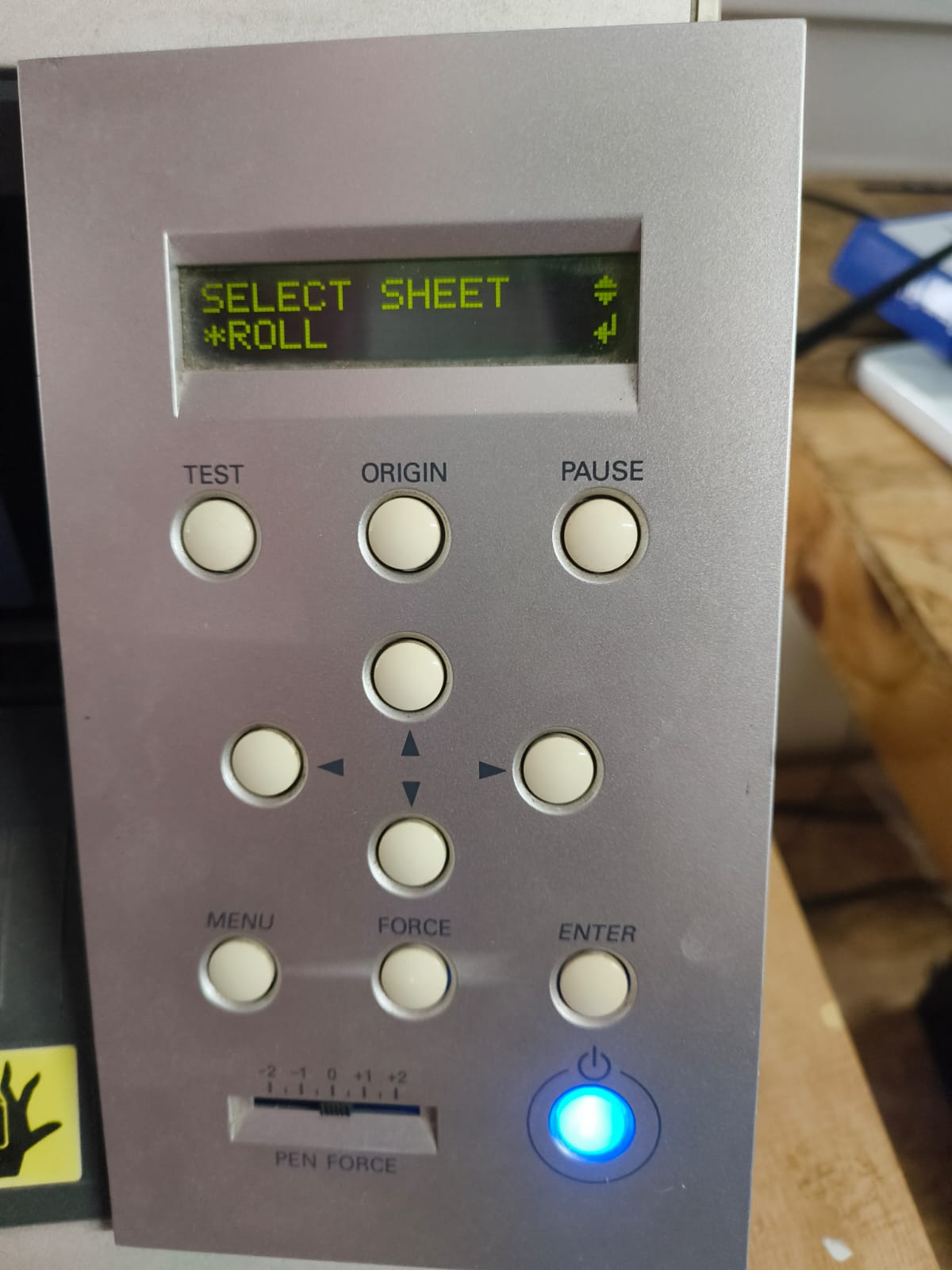
The correct option was selected based on the material used.
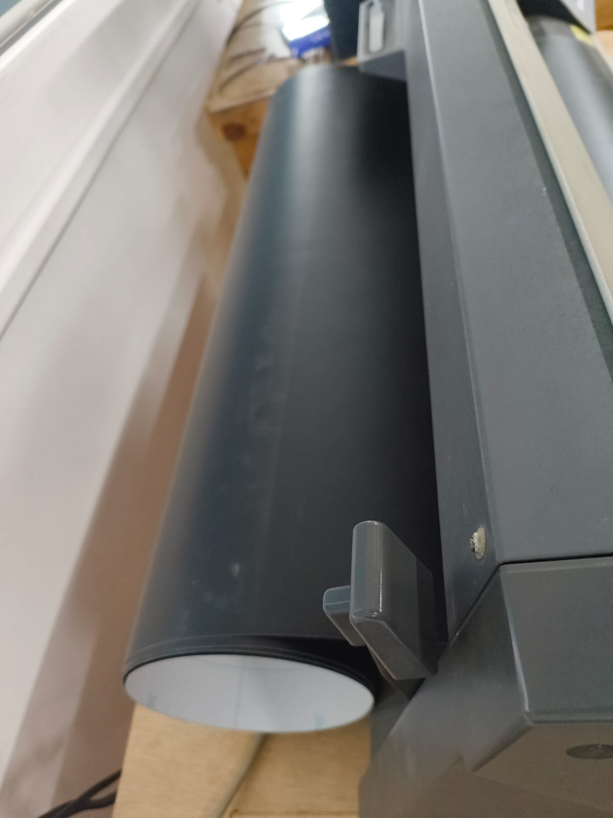
Loading the Material
Vinyl is inserted from the back of the machine, similar to loading paper into a printer.
The material is aligned straight before clamping to avoid skewing during cutting.
Clamped the vinyl material securely.
Pinch Roller Positioning
The vinyl cutter uses pinch rollers (wheels) to grip the material.
It is important to ensure that:
- The rollers are positioned only on the white striped areas of the machine bed.
- If any roller is placed outside these marked zones, the machine will display a “Bad Position” error and refuse to operate.
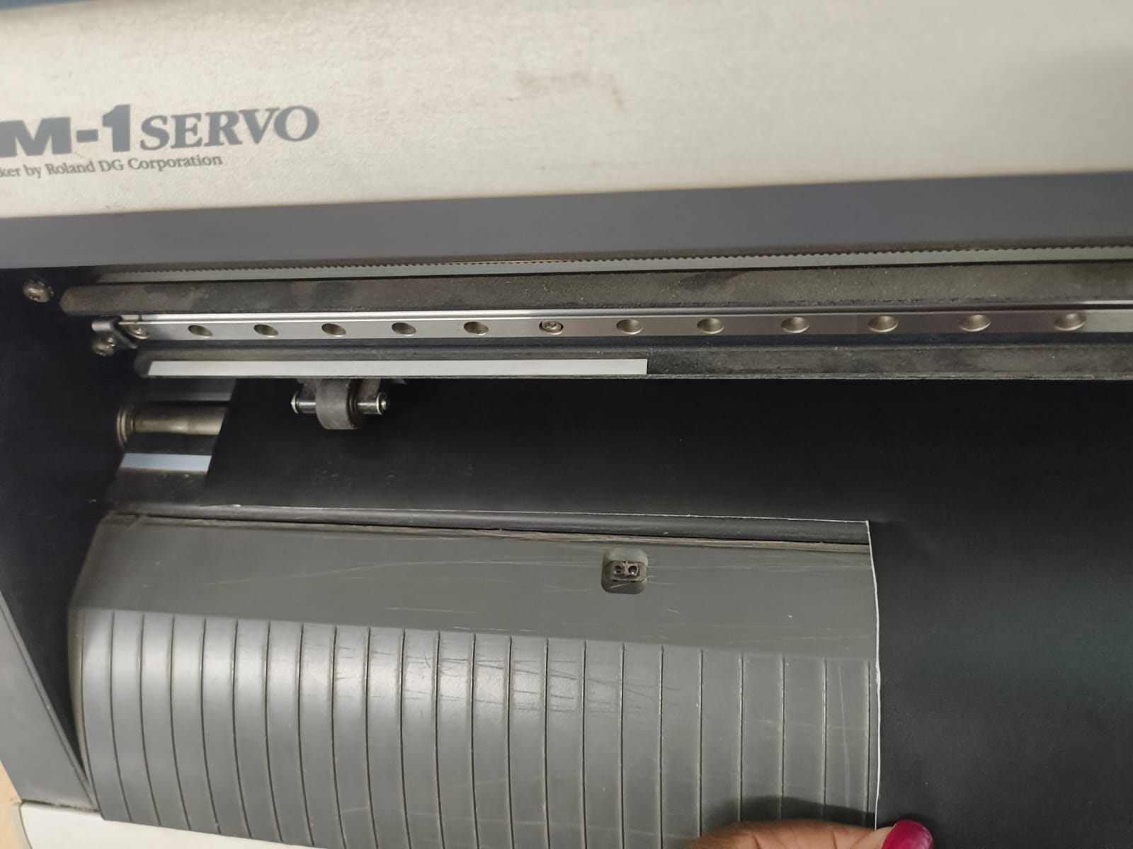
Correct roller placement ensures proper tracking and accurate cutting.
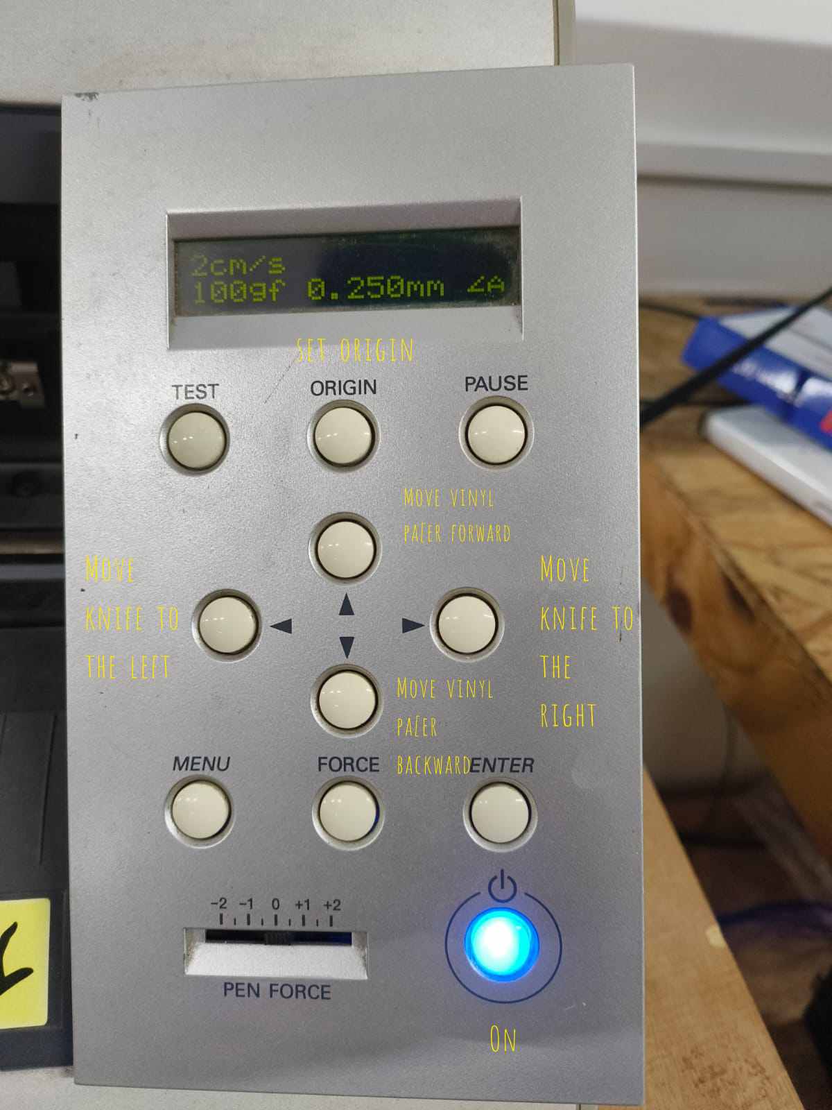
Setting Origin and Cutting
- The arrow keys on the control panel were used to move the blade to the desired starting position.
- The Origin button was pressed to set the cutting origin.
- Cutting force and speed were verified.
- The file was sent from Mods to the machine.
- The vinyl cutter executed the cut based on the vector paths.

Laser Cutting
Laser cutting is an advanced thermal cutting technology that uses a focused, high-powered laser beam to precisely cut, engrave, or etch various materials. Since its commercial introduction in the 1960s, laser cutting has revolutionized manufacturing processes across numerous industries, offering unparalleled precision and versatility.
The technology works by directing a concentrated beam of light energy at the material surface, heating it to melting or vaporization point. This process creates clean, accurate cuts with minimal mechanical stress on the workpiece. Modern laser cutting systems can achieve tolerances as tight as ±0.1mm, making them ideal for applications requiring extreme accuracy. The laser optics and CNC (computer numerical control) are used to direct the laser beam to the material.
A commercial laser for cutting materials uses a motion control system to follow a CNC or G-code of the pattern to be cut onto the material. The focused laser beam is directed at the material, which then either melts, burns, vaporizes away, or is blown away by a jet of gas, leaving an edge with a high-quality surface finish.
Laser Cutting Process
Software and Tools Used
- Autodesk Fusion 360 (Sketch and Parametric Design)
- Laser Cutter
- Calipers (for measuring material thickness)
- Sheet material (e.g., plywood or acrylic)
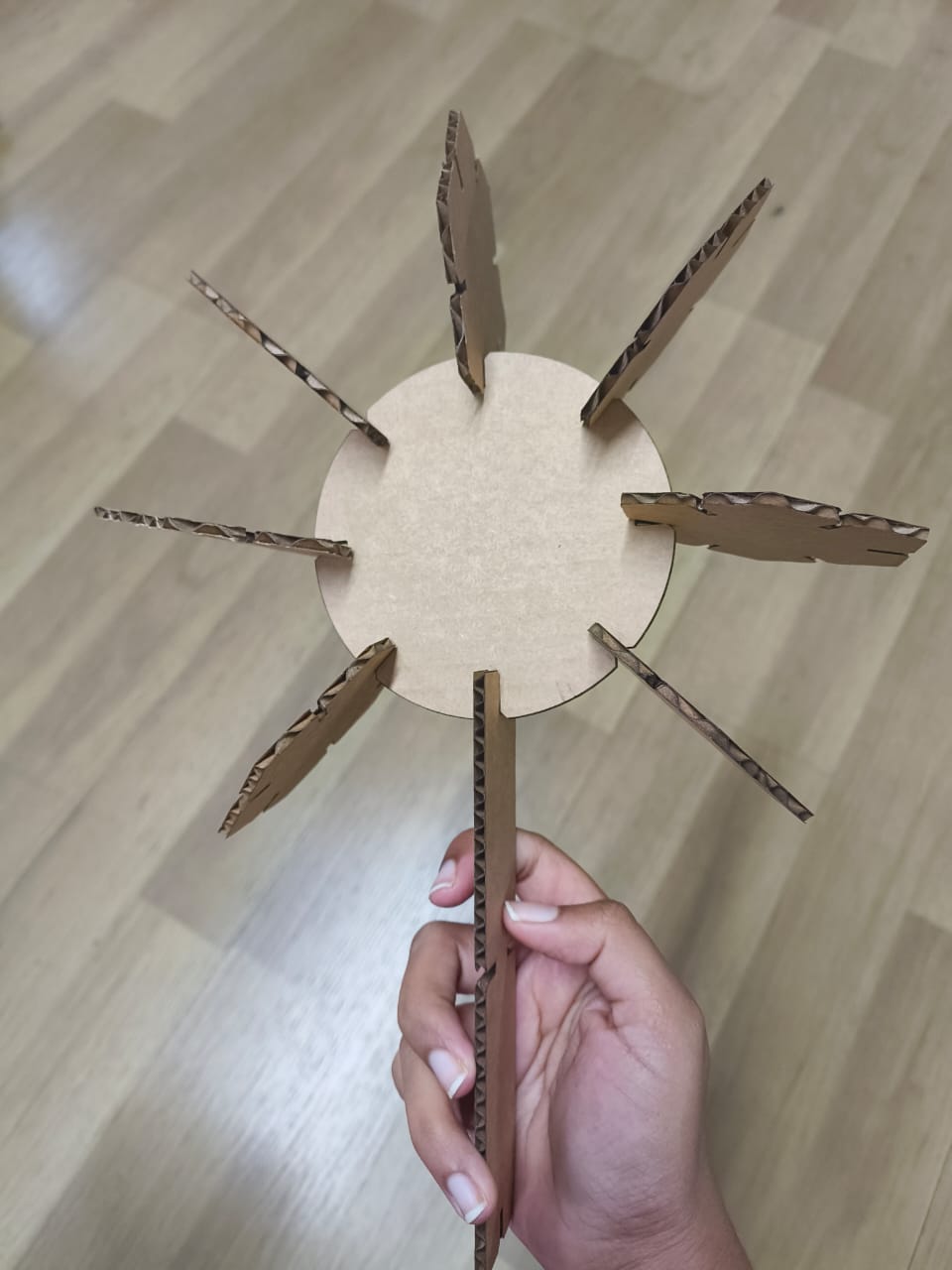
Construction Kit
Slot Design for Circular Construction Kit
The design process began by downloading a Frozen movie ice motif image from the internet here.

Since the image was a raster file, it was first opened in Inkscape, where the Trace Bitmap tool was used to convert the image into vector paths. After tracing, the design was exported as an SVG file.

This SVG file was then imported into Autodesk Fusion 360, where it was used as the central decorative engraving element for the construction kit.
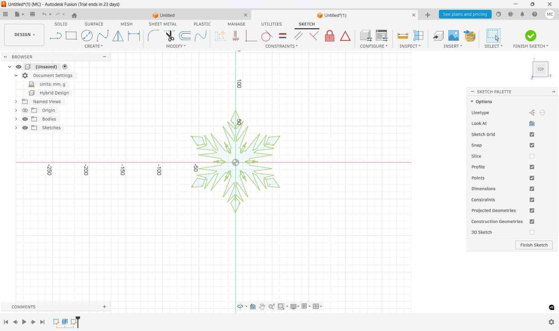
To create the base geometry, two concentric circles were drawn around the imported ice design. These circles defined the main structural boundary of the piece.
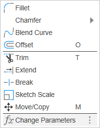
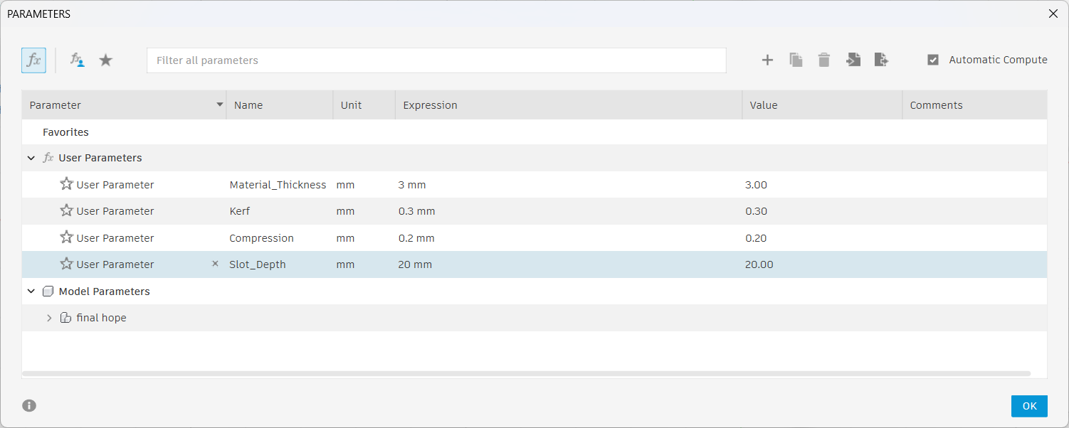
Then I addded parameters to the design. i went to modify, and Change Parameters.
By clicking on the plus symbol on the toolbar, you can create a new parameter.
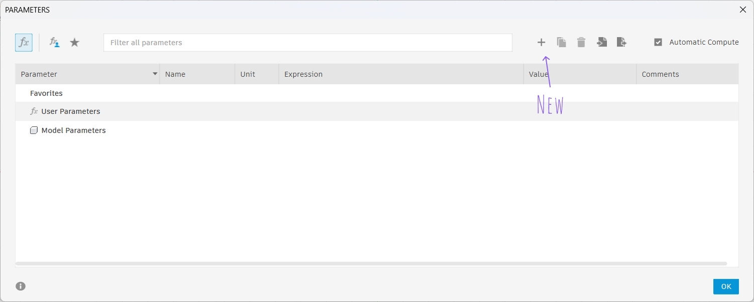
Click ok on the window that appears. Then you can see this window on your screen:
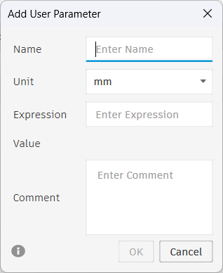
Here, I created a parameter for material thickness, kerf, compression and slot width. The slot width was defined as 'Material Thickness - Kerf - Compression'.
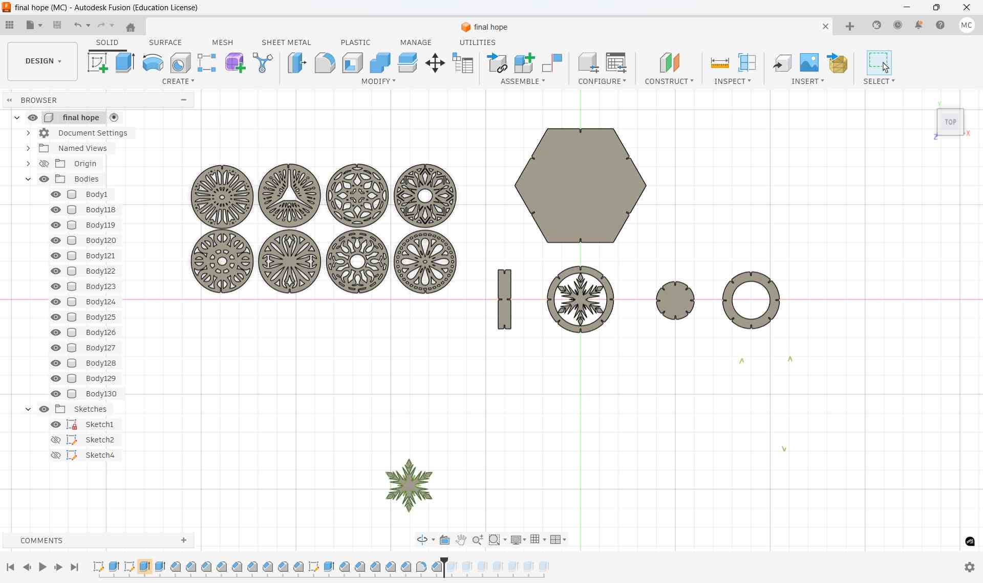
After this, I created some basic shapes I liked for the kit.
Slot Creation and Placement
A rectangle was drawn to define the slot geometry. The width of the rectangle was set using the calculated 'Material Thickness - Kerf - Compresssion', and the height was defined based on the required slot depth.
I used the center rectangle tool to create a centered rectangle with the calculated dimensions to the shapes. This helped me to align the shapes without too much difficulty.
Then i selected the rectangke I drew and went to Create, CIrcuolar Pattern and applied the slots around the shape like a pattern.
I also downloaded anothe image file from here. I inserted it into Fusion as SVG. After finishing the sketch, I extruded the shapes.
How the Adjustable Bed Works
The bed moves vertically using an internal motor system.
From the control panel (as shown in the image):
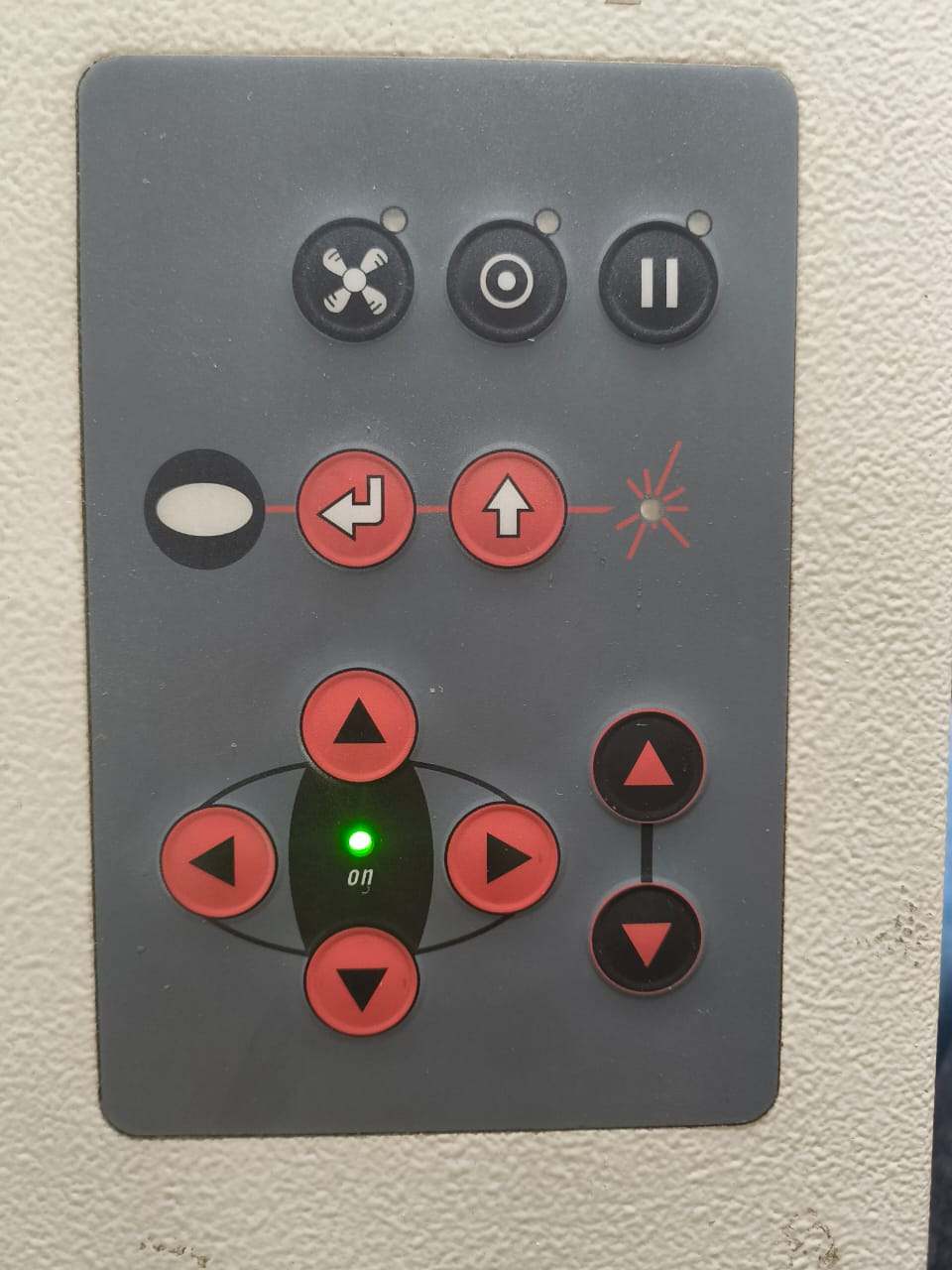
- ▲ Up arrow → Raises the bed
- ▼ Down arrow → Lowers the bed
The movement adjusts the distance between:
- The laser head (fixed above)
- The material surface (on the bed)
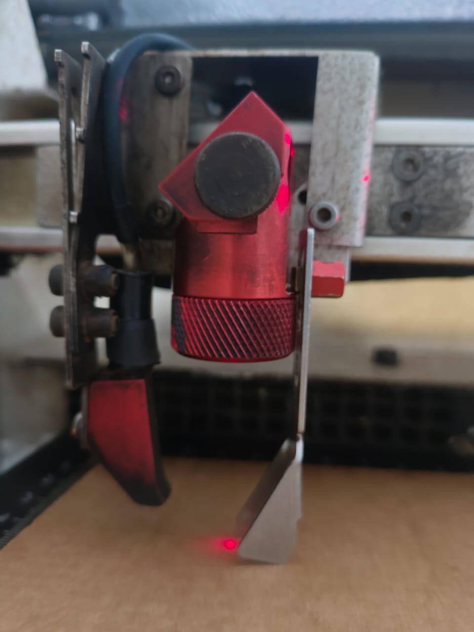
Focusing Process
- Place the material on the bed.
- Use the up/down buttons to raise or lower the bed.
- Use the focus tool (Trotec focus gauge) to set the correct focal height.
- Adjust until the focus tool just touches the material surface.
Once focused, the laser beam converges at the exact surface point, ensuring optimal cutting performance, clean edges, and accurate kerf.