COMPUTER-AIDED DESIGN
The objective of Week 2 was to learn the fundamentals of Computer-Aided Design (CAD) and explore both 2D and 3D design tools. This week focused on creating parametric and non-parametric models, understanding file formats, and preparing designs for digital fabrication.
In this week’s assignment, I explored different types of digital design models and documented a possible final project. The work includes raster, vector, 2D, and 3D design workflows using multiple design tools.
This page serves as a record of my learning and experimentation during Week 2 of the Fab Academy.
Topics Covered
- Introduction to Computer-Aided Design
- Difference between raster and vector graphics
- Parametric vs non-parametric design
- 2D Design of Final Project
- 3D Design of Final Project
Softwares Used
2D Design & Graphics
- Figma
Used for creating the 2D conceptual design of the pill dispenser, including layout planning, interface elements, and visual representation of functional components.
- Inkscape
Used for vector graphics creation and bitmap tracing to convert raster images into scalable vector formats.
- Photopea
Used for raster image editing, background removal, layout refinement, and preparing images for documentation.
3D Design & Modeling
- Autodesk Fusion 360
Used for parametric 3D modeling of the pill dispenser, including sketching, solid modeling, feature creation, assembly, rendering, and exporting models for fabrication and animation.
- Blender
Used for non-parametric 3D modeling, surface refinement, animation, and rendering of the design. Also used to create and render the final animated video.
- Tinkercad
Used for basic 3D modeling using primitive shapes and boolean operations to explore form and functional layout in a beginner-friendly environment.
Animation & Rendering
- Blender (Animation Workspace)
Used to animate the final 3D model using keyframes, transformations, camera setup, and rendering animations as video files.
Media Optimization
- HandBrake
Used to compress video files for web use, reducing file size while maintaining visual quality.
- Windows Photos (Built-in Tool)
Used for basic image resizing and compression.
- Online Image Compression Tool (Image Compressor)
Used to compress images for web use, reducing file size while maintaining visual quality.
File Formats
- FBX
Used to transfer 3D models from Fusion 360 to Blender for animation
- STL / DXF
Used for 3D printing and CAD software compatibility.
- PNG / JPG / MP4
Used for web and media compatibility.
Introduction to Computer-Aided Design
Computer-Aided Design (CAD) is the use of computer software to create, modify, analyze, and optimize designs.
CAD allows designers to create precise and accurate models in both two-dimensional (2D) and three-dimensional (3D) forms. These digital models can be easily edited, scaled, and exported into different file formats suitable for fabrication.
Difference between raster and vector graphics
Raster and vector graphics are two different ways of representing images.
Raster images are created with pixel-based software or captured with a camera or scanner. They are more common in general such as jpg, gif, png, and are widely used on the web.
Vector graphics use geometric shapes (points, lines, curves) defined by mathematical equations to create images. Vector graphics are math-defined shapes created with vector software and are not as common; used in CAD/engineering, 3D animation, and in Graphic Design for processes that reproduce an image on an object without ink or paint, such as engraving, etching, cut stencils.
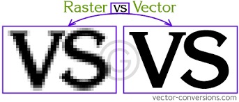
The image below compares raster and vector graphics, highlighting the key differences between the two image types.
Raster Image Example
The image below is an example of a raster image. Raster images are made up of individual pixels and can lose quality when scaled or enlarged.
Vector Image Example
The image below is an example of a vector image. Vector images are created using paths and mathematical formulas, allowing them to be resized infinitely without any loss of quality.
Parametric and Non-Parametric Design
Parametric Design
Parametric design is a modeling approach where the geometry of a design is defined by parameters, dimensions, and constraints. The relationships between different features are maintained, so changes made to one part of the model automatically update the related features.
Key Characteristics
- Dimensions and constraints control the design
- Design elements are linked and dependent on each other
- Changes propagate automatically throughout the model
- Design intent is preserved
Example
If the width of a rectangle in a sketch is changed, any 3D features created from that sketch (such as extrusions or holes) update automatically.
Advantages
- Easy to modify and iterate designs
- Maintains consistency and accuracy
- Ideal for engineering and fabrication workflows
- Supports design reuse and scalability
Common Tools
- Fusion 360
- FreeCAD
- SolidWorks
Non-Parametric Design
Non-parametric design (also known as direct modeling) focuses on manually shaping geometry without maintaining relationships between features. Changes are applied directly to the geometry, and modifying one feature does not automatically update others.
Key Characteristics
- Geometry is edited directly
- Features are not linked by constraints
- Design changes must be adjusted manually
- More flexible but less controlled
Example
Stretching or reshaping a 3D object by dragging faces without changing underlying sketch dimensions.
Advantages
- Faster for conceptual and artistic work
- More intuitive for beginners
- Suitable for visual design and early-stage concepts
Common Tools
- Blender
- Figma (for 2D conceptual design)
- Mesh-based editors
2D Design
For this assignment, I used Figma and Photopea for creating, refining, and presenting 2D designs. These tools supported both vector-based layout design and raster-based image editing. Using them together helped me develop clear conceptual models and well-prepared documentation visuals.
Figma
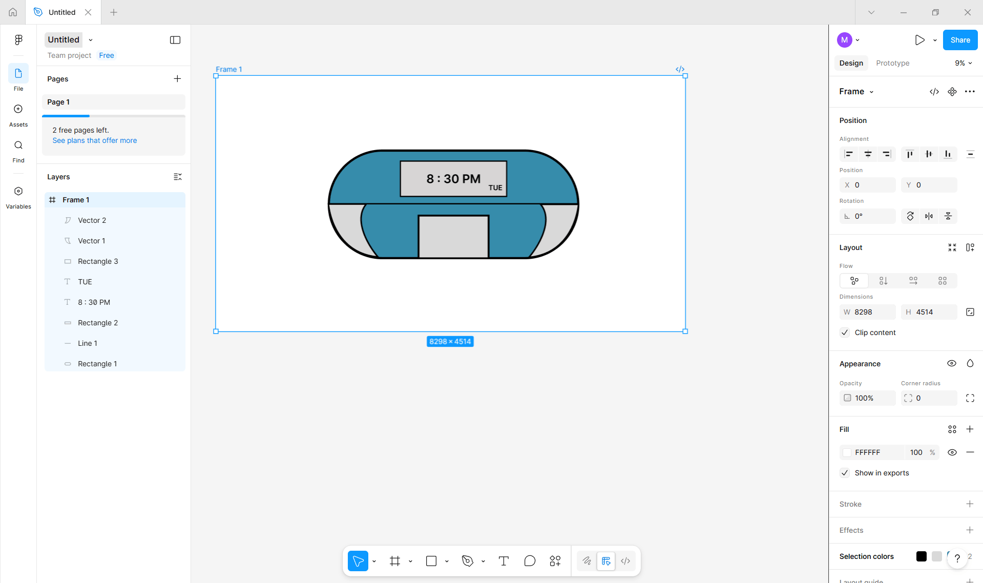
For this assignment, I developed a 2D conceptual model of my final project using Figma. The objective of this design was to visualize the overall form, layout, and key functional components of a pill-shaped pill dispenser before moving into 3D modeling and fabrication.
Link to the Website is here.
Base Body Design
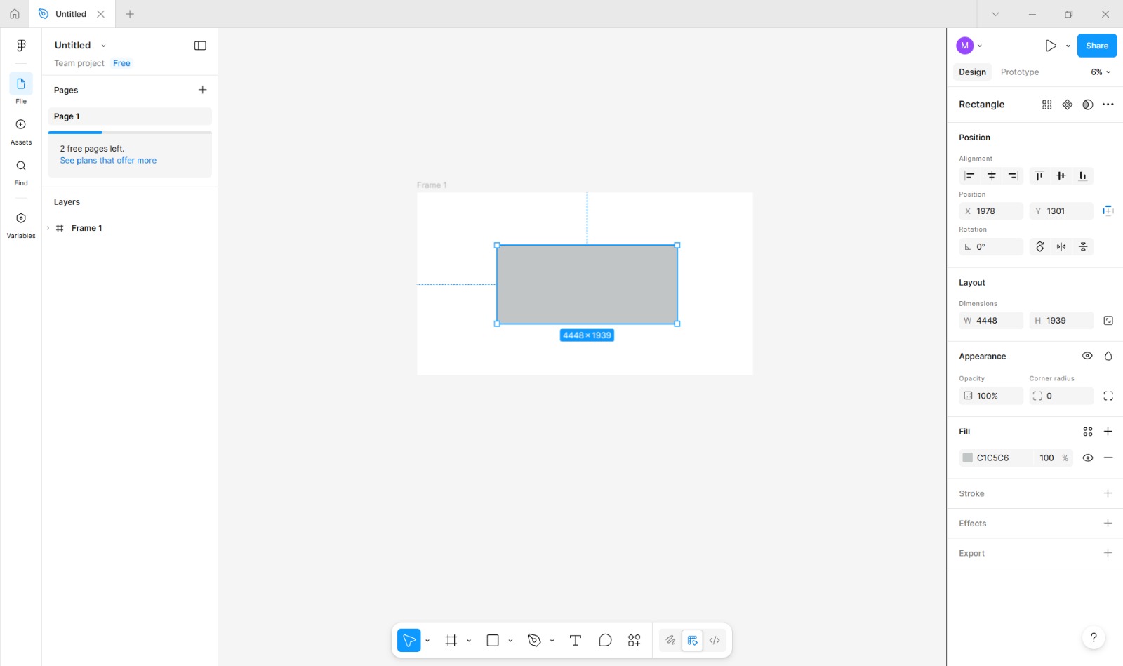
Accessing the Rectangle Tool
I selected the Rectangle Tool from the main toolbar located on the bottom side of the workspace. (Shortcut: Press R on the keyboard.)
After drawing the rectangle, I switched to the Selection Tool (shortcut: V) and clicked on the shape to make sure it was active for further modifications.
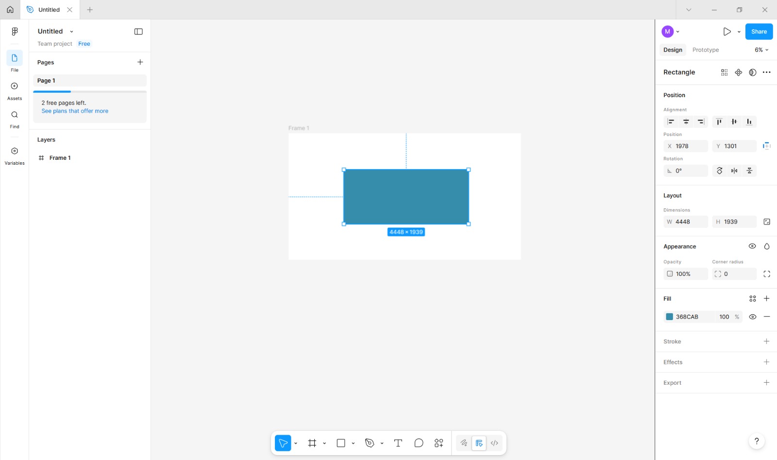
Applying Fill Color
While the shape was still selected, I went to the Fill section in the Properties Panel.
I clicked on the color selector and chose a solid color from the palette.
This color was applied to distinguish the device body from the background.
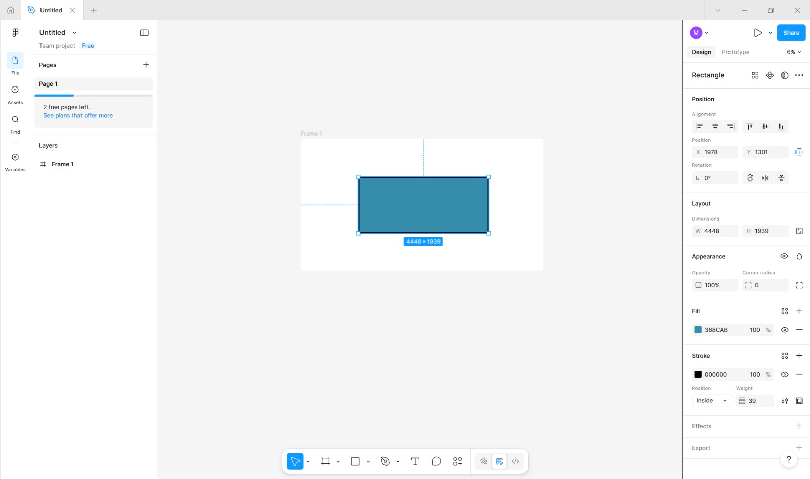
Adding a Stroke (Outline)
Next, I opened the Stroke/Border settings in the same Properties Panel.
I enabled the stroke option and selected black as the stroke color.
I adjusted the stroke width slider to achieve a visible but balanced outline around the shape.
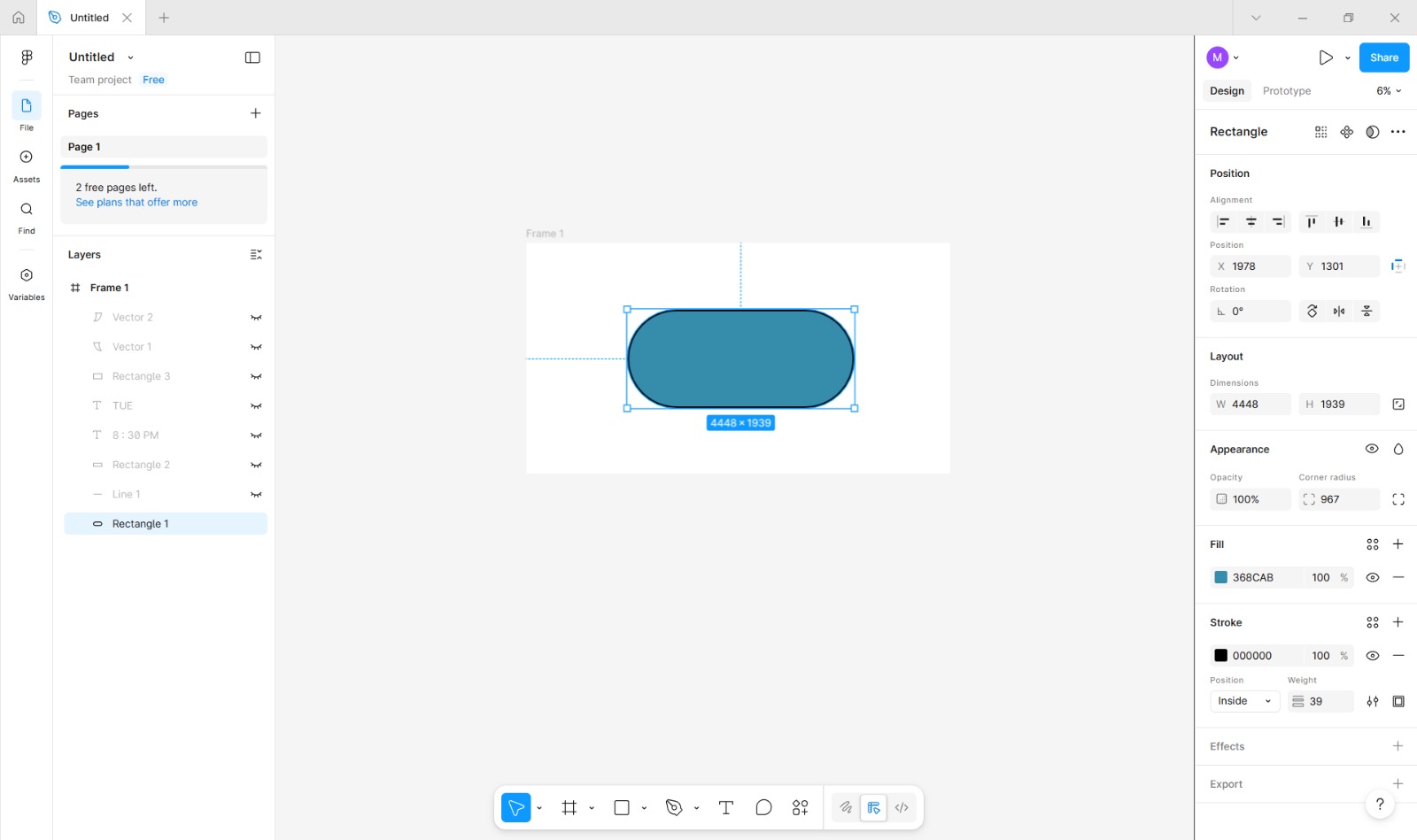
Applying Border Radius (Corner Rounding)
With the rectangle selected, I navigated to the Properties/Design Panel on the right side of the interface.
In the Corner Radius or Border Radius section, I located the radius input fields.
I increased the radius value manually by typing in the maximum allowed number or by dragging the radius control until all four corners became fully rounded, forming a pill-shaped outline.
If the software displayed individual corner controls, I ensured that all corners were linked so they would round evenly.
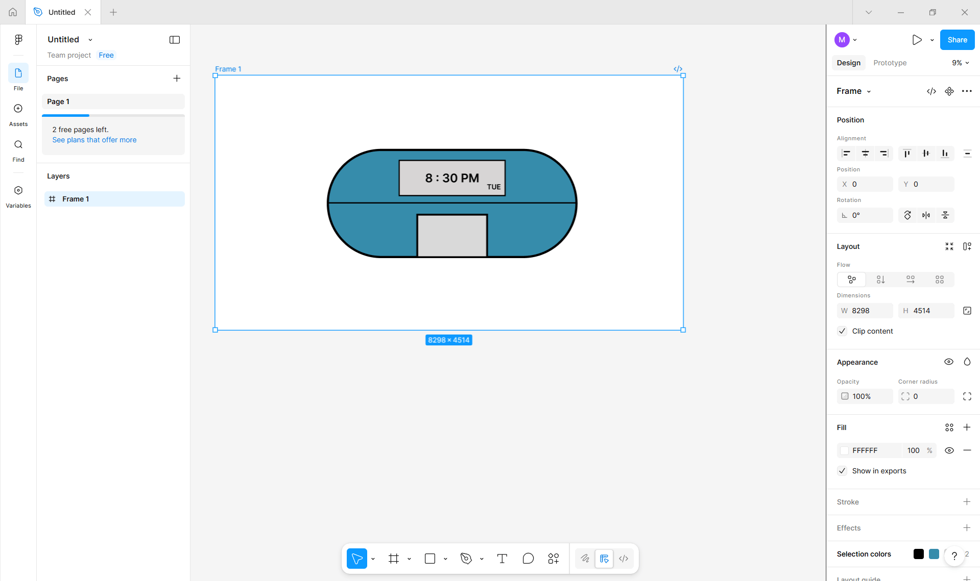
Final Positioning and Adjustment
Using the Selection Tool, I repositioned the shape on the canvas by clicking and dragging it into the correct location.
Minor size adjustments were made by dragging the side handles while holding Shift to maintain proportions.
Refill Opening Indication
Accessing the Line Tool
I selected the Line Tool from the main toolbar located on the bottom toolbar of the workspace. If the Line Tool was grouped with other shape tools, I clicked and held the shape icon until the extended menu appeared, then selected the Line Tool.
(Shortcut: Press L on the keyboard.)
Drawing the Opening Line
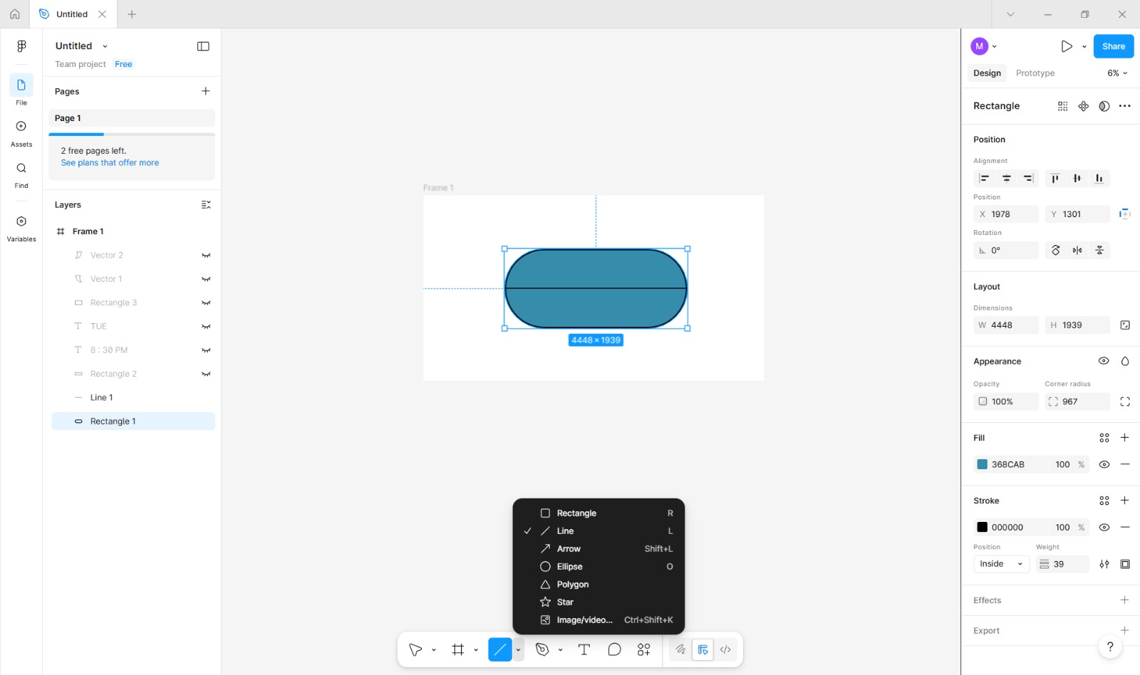
After selecting the Line Tool, I clicked on one end of the pill-shaped body and dragged the cursor horizontally to the opposite end to create a straight line.
I held the Shift key while dragging to ensure that the line remained perfectly horizontal.
Adjusting Line Thickness
With the line selected, I opened the Properties Panel on the right side of the interface.
In the Stroke or Border section, I located the stroke width input field or slider.
I increased the stroke width value manually until the line was thick enough to be clearly visible and consistent with the overall design.
Representing the Refill Seam
This line represents the opening seam of the dispenser.
It indicates the section that can be opened by a caretaker for refilling medication.
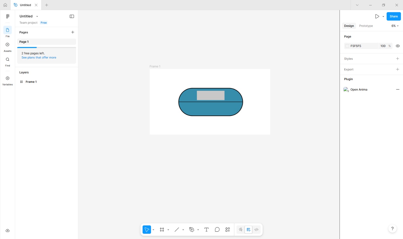
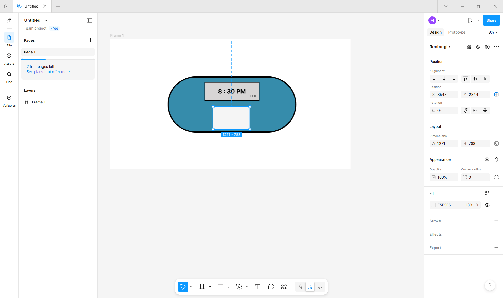
LED Display Representation
Accessing the Rectangle Tool
I selected the Rectangle Tool from the main toolbar located on the bottom side of the workspace. If the tool was grouped with other shape tools, I clicked and held the shape icon to reveal the extended menu and then selected the Rectangle Tool.
Creating the Display Area
Using the Rectangle Tool, I clicked and dragged on the canvas to draw a smaller horizontal rectangle on the front surface of the device body.
This rectangle represents the LED display screen.
I adjusted the size and position using the selection handles to ensure it was centered and proportionally aligned with the main body.
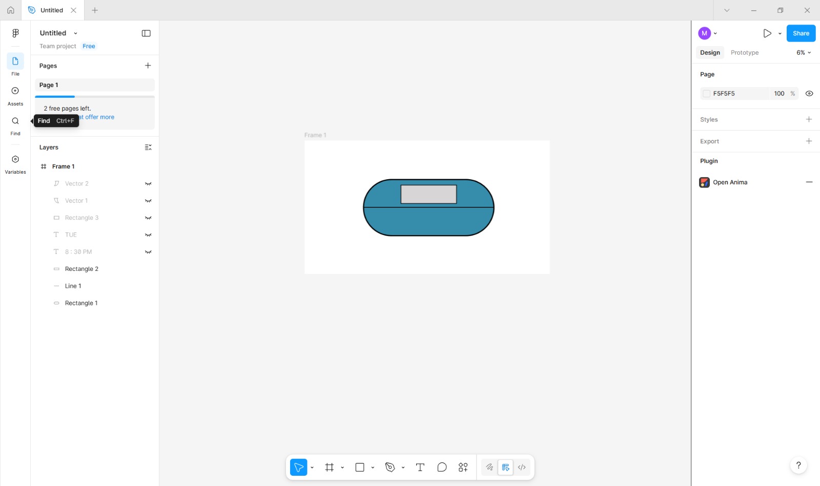
Styling the Display Screen
With the display rectangle selected, I opened the Properties Panel.
In the Fill section, I applied a different color to simulate the appearance of an inactive LED screen.
I adjusted the border settings to create a subtle outline around the display area.
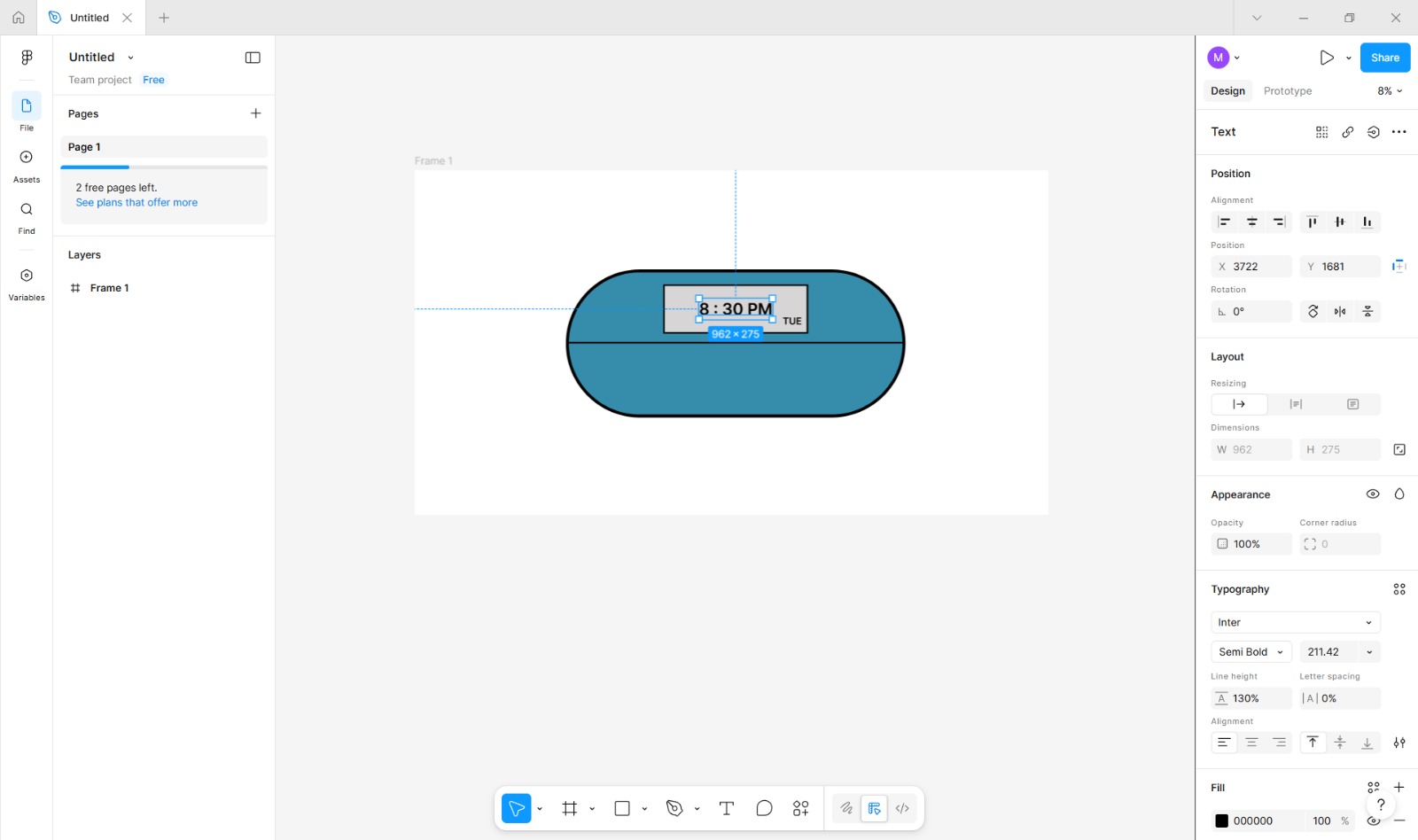
Adding Sample Display Text
I selected the Text Tool from the toolbar.
(Shortcut: Press T on the keyboard.)
I clicked inside the display rectangle and typed sample content such as “8:30 PM” and “TUE” to represent realistic time and date information.
I adjusted the font size, alignment, and color in the Properties Panel to ensure the text was clearly readable within the display area.
Visualizing User Interaction
The sample text helped demonstrate how scheduled medication reminders would appear to the user during normal operation.
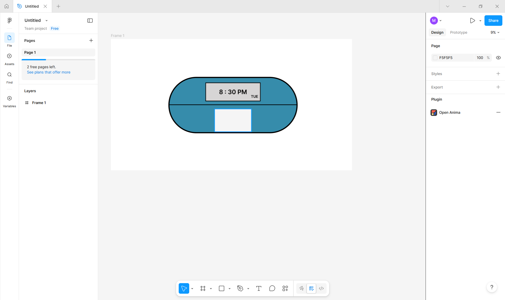
Medicine Dispensing Slot
Accessing the Rectangle Tool
I selected the Rectangle Tool from the main toolbar located on the left side of the workspace. If the tool was grouped with other shape tools, I clicked and held the shape icon to reveal the extended menu and then selected the Rectangle Tool.
Creating the Dispensing Slot Shape
Using the Rectangle Tool, I clicked and dragged on the canvas to draw a small horizontal rectangle near the bottom edge of the main device body.
This rectangle represents the medicine dispensing slot.
Positioning and Aligning the Slot
After drawing the slot, I switched to the Selection Tool (shortcut: V).
I repositioned the rectangle by dragging it until it was centered horizontally and aligned with the lower portion of the device body.
I used alignment guides and spacing indicators to ensure accurate placement.
Adjusting Appearance
With the slot selected, I opened the Properties Panel.
In the Fill section, I applied a darker shade to distinguish the slot from the main body.
I navigated to the Border or Stroke settings and selected a border color that complements the overall design.
I adjusted the border thickness and style to maintain visual consistency with other elements on the device.
Defining User Interaction Point
The position of the dispensing slot establishes the primary interaction area where the patient retrieves the medication.
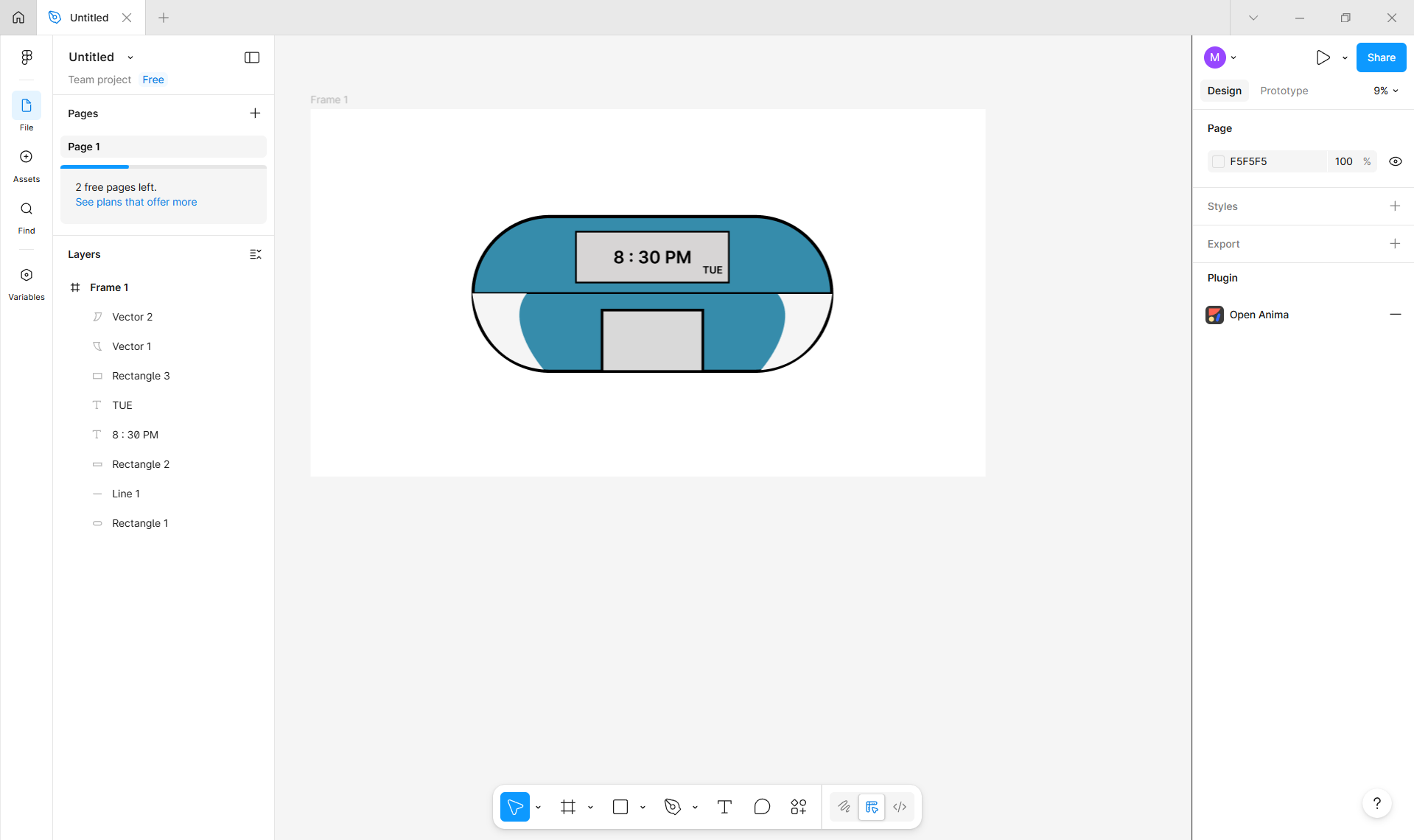
Decorative Side Elements
To improve the visual appeal of the device, I added decorative elements along the sides using the pen tool.
These elements are purely aesthetic and do not serve a functional purpose.
Accessing the Pen Tool
I selected the Pen Tool from the main toolbar located on the left side of the workspace. If the Pen Tool was grouped with other drawing tools, I clicked and held the icon to reveal the extended menu and then selected the Pen Tool.
(Shortcut: Press P on the keyboard.)
Creating Decorative Shapes
Using the Pen Tool, I clicked along the sides of the device body to place anchor points and draw custom paths.
I adjusted the direction handles while placing points to create smooth, flowing curves that follow the contour of the device.
Refining the Decorative Elements
After completing each path, I switched to the Selection Tool (shortcut: V) to fine-tune the shape by adjusting individual anchor points and curves.
I modified the stroke settings in the Properties Panel to ensure the decorative lines were visually consistent with the rest of the design.
These elements are purely decorative and were added to enhance the overall visual appeal of the device. They do not serve a functional purpose and were included solely to improve the aesthetic balance of the design.
Purpose of the 2D Design
This 2D design acts as a conceptual and visual reference for the final project.
It helped in planning:
- Overall form factor
- Placement of functional components
- User and caretaker interaction areas
Using Figma allowed for quick iteration and easy modification before proceeding to detailed CAD design.
Inkscape
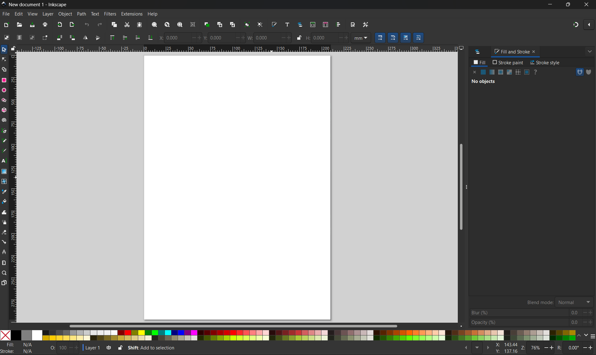
Inkscape is a powerful, free, and open-source vector graphics editor used to create scalable images like logos, icons, illustrations, and diagrams, working with paths and points instead of pixels for infinite resolution.
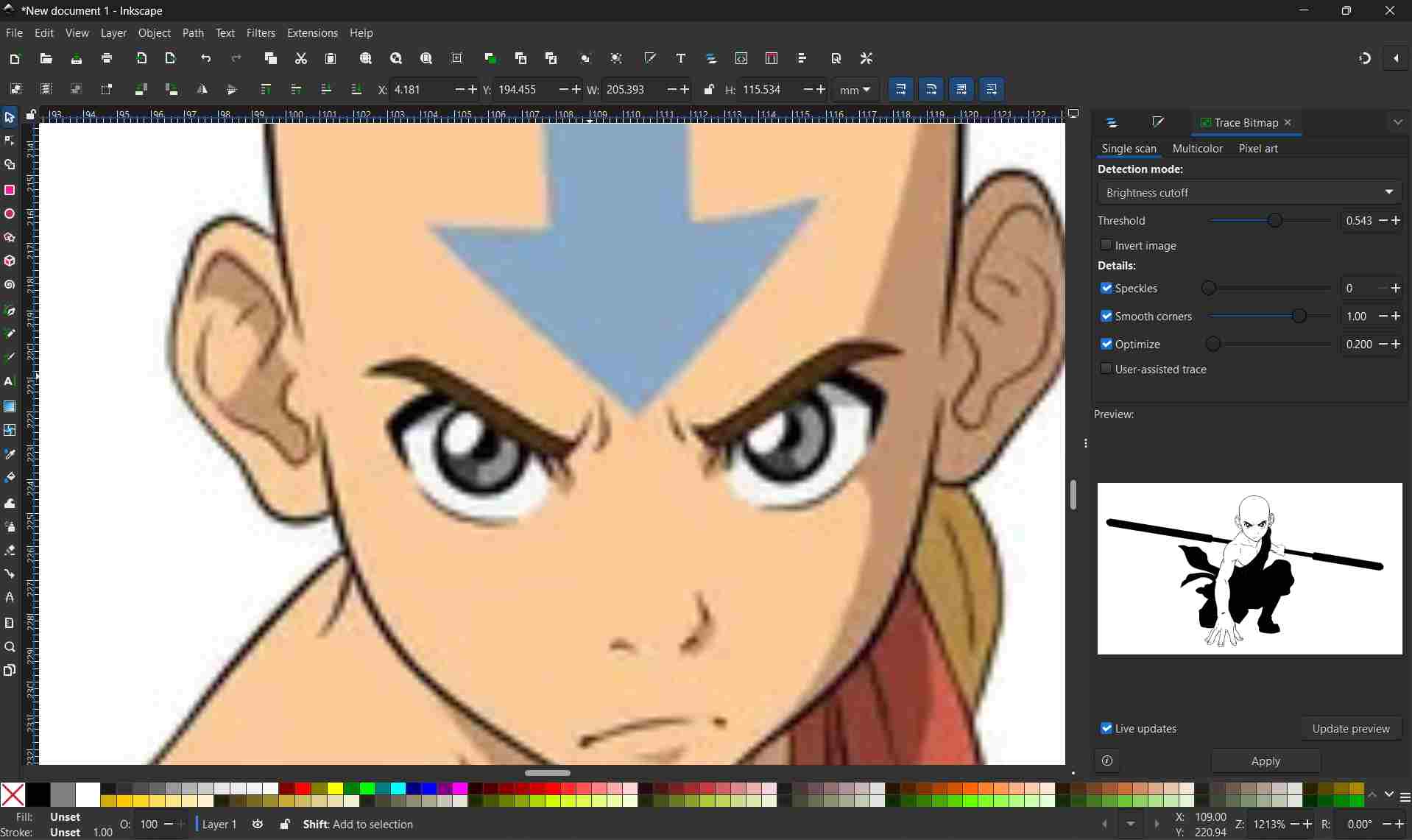
The image below shows the Inkscape user interface, highlighting the main workspace, toolbars, and design canvas used during the creation and editing of vector graphics.
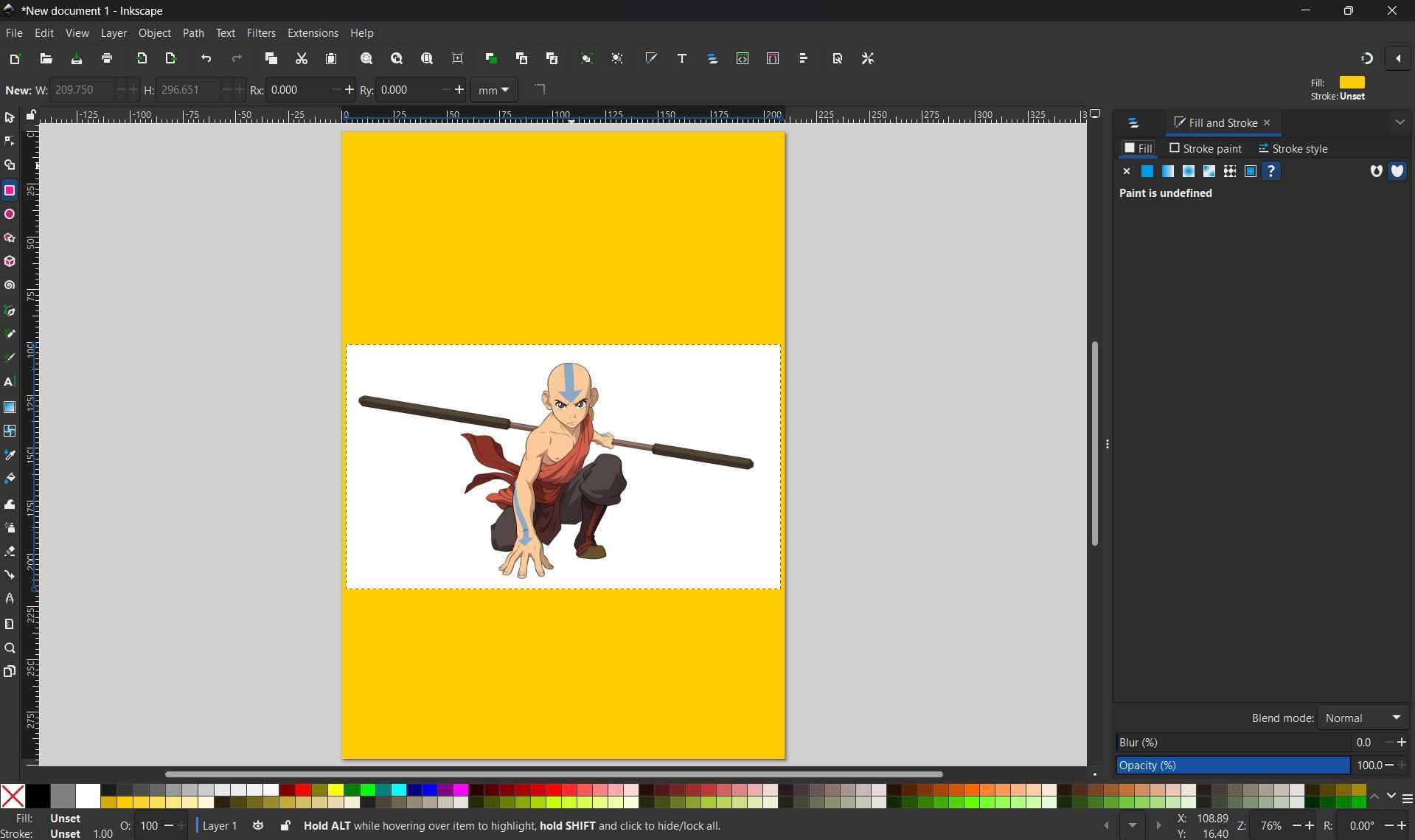
Import the Image
To begin the vectorization process, I imported an external image into Inkscape by selecting File > Import from the top menu.
The image below shows the imported raster image placed onto the canvas and positioned within the workspace for further editing.
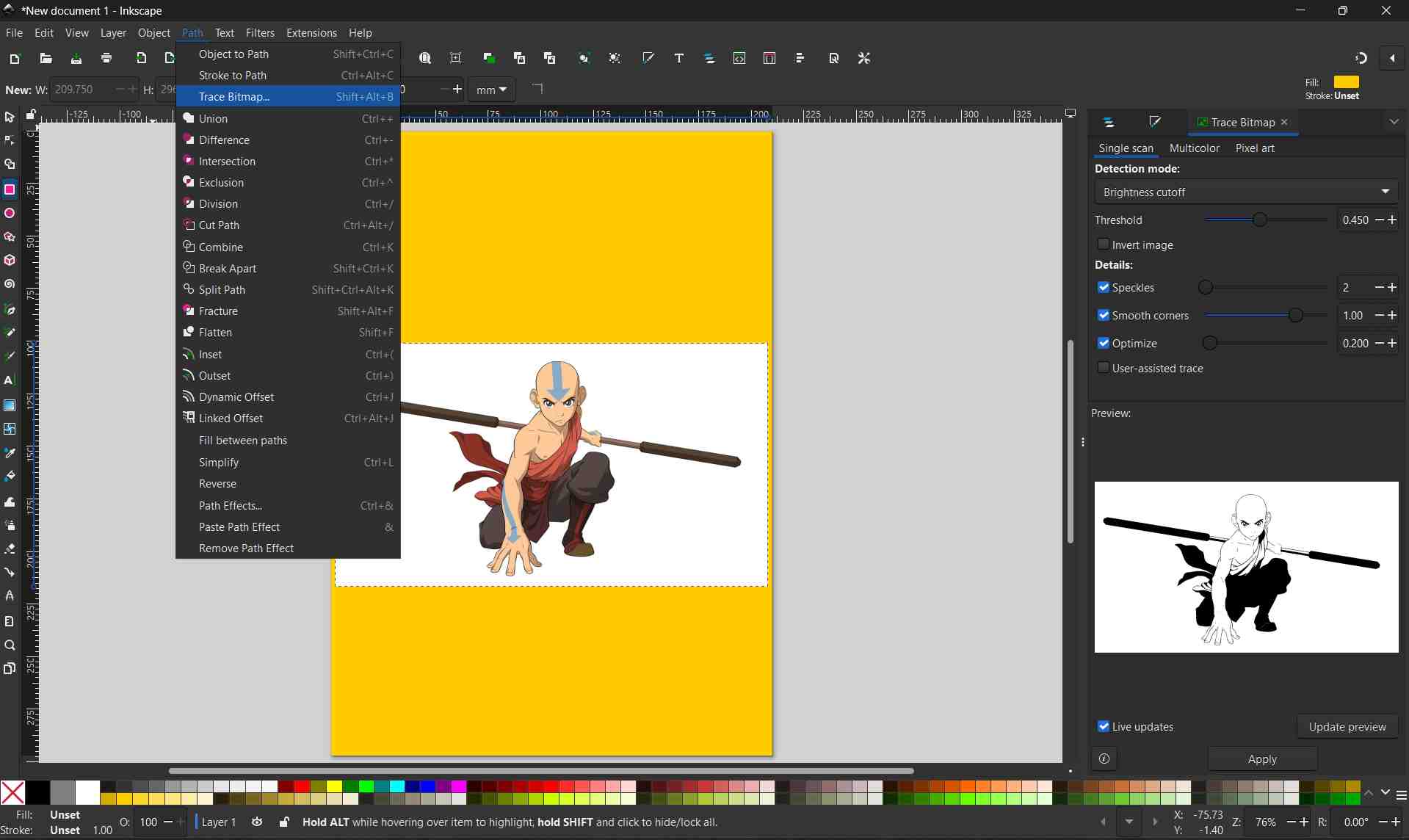
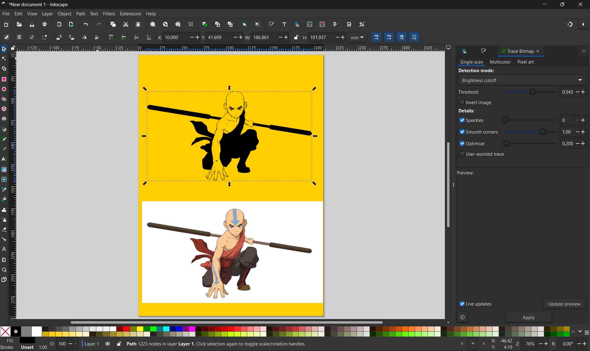
Tracing the Bitmap
With the imported image selected, I accessed the bitmap tracing tool by navigating to Path > Trace Bitmap.
The image below shows the Trace Bitmap panel, where tracing settings were adjusted to convert the raster image into vector paths.
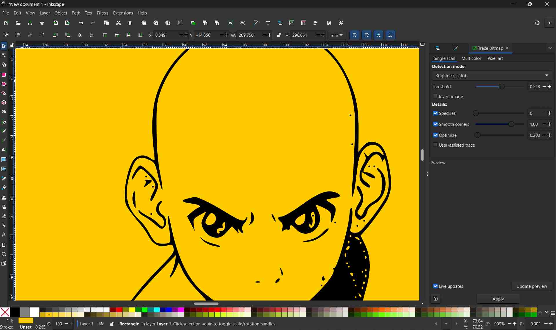
Creating the Vector Bitmap
After applying the Trace Bitmap settings, Inkscape generated a vector version of the original image.
The image below shows the completed bitmap trace, with the vector object created on top of the original raster image.
Photopea
In addition to Figma, I used Photopea as a raster-based and lightweight design tool to experiment with layout, visual appearance, and basic editing of my 2D concept.
Photopea was accessed through a web browser and did not require local installation. It was used mainly for raster image editing and documentation preparation. Photopea supports layered editing and multiple file formats, which made it useful for working with screenshots and exported images.
Photopea is a free, web-based image editing software that supports both raster and vector graphics. It functions similarly to Adobe Photoshop and allows users to edit images, remove backgrounds, and apply various selection and editing tools directly in a web browser without installing additional software.
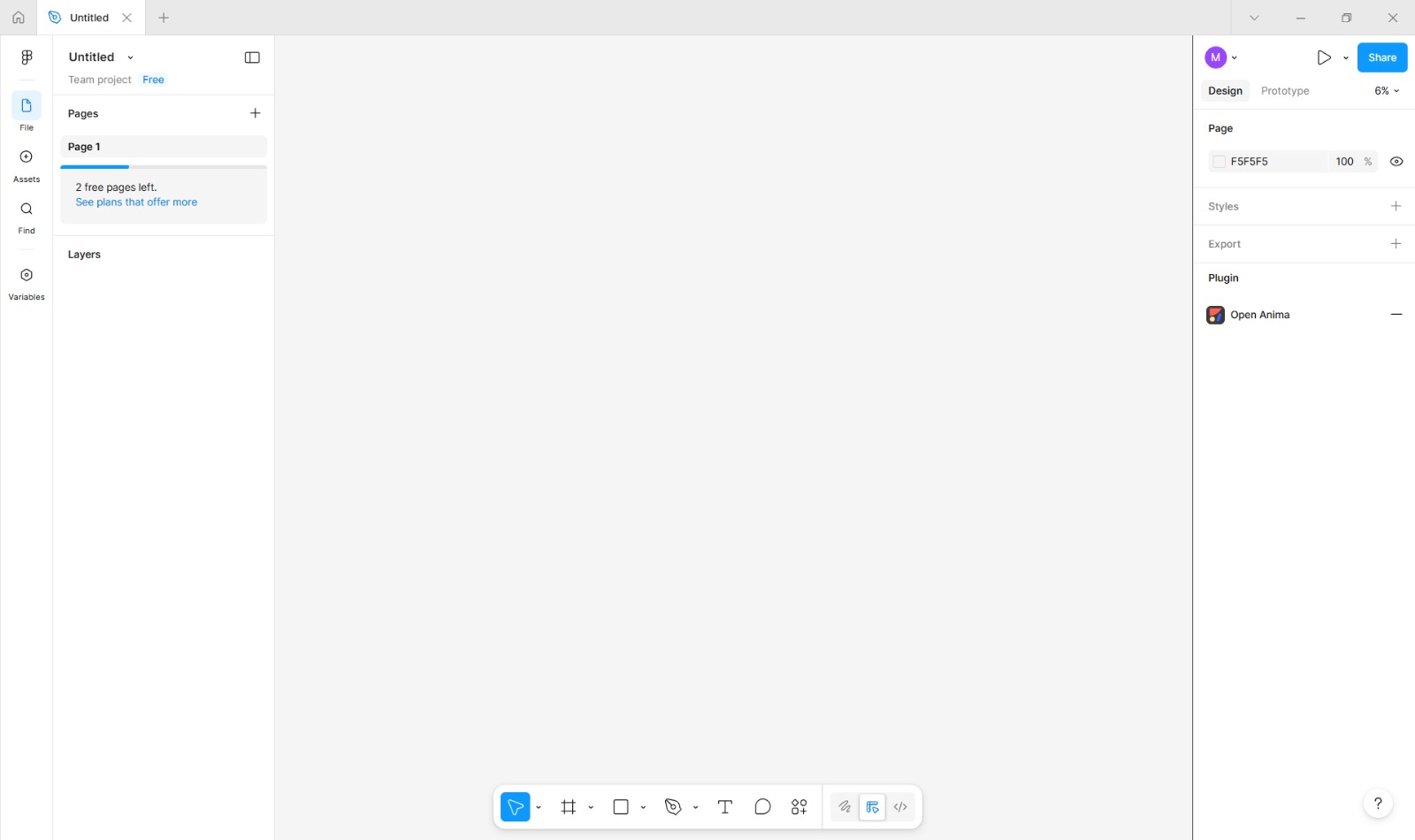
Creating a New Project

I opened Photopea and started a new project by clicking New Project from the home screen.

From the available preset options, I selected the Facebook Event Page canvas size to ensure the design met standard social media dimensions.

Importing an Image
After creating the project, I imported an image by selecting File > Open.
The imported image was placed onto the canvas as a new layer.
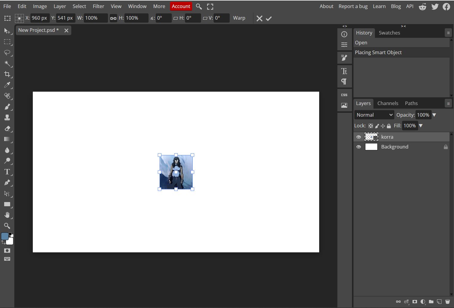
Resizing the Image
With the image layer selected, I activated the Transform controls.
I resized the image by dragging the corner handles while holding the Shift key to maintain its original proportions.

Using the Magic Eraser Tool
To remove unwanted background areas, I selected the Magic Eraser Tool from the toolbar.
By clicking on areas of similar color, the tool automatically removed pixels based on color similarity.

Refining the Selection with the Lasso Tool
For more precise editing, I selected the Lasso Select Tool from the toolbar.
I manually drew a selection around specific parts of the image that needed to be removed.
Once the selection was complete, I pressed the Delete key to remove the selected portion of the image.

Final Image Editing
By combining automated tools like the Magic Eraser with manual selection using the Lasso Tool, I was able to clean and refine the image for the final design.

Outcomes
Using Figma, inkscape and Photopea together improved my understanding of vector and raster design workflows. Figma was more suitable for structured, scalable layouts, while Photopea was more effective for image editing and presentation. Learning how to select and combine these tools helped me document my work more clearly and prepare for future digital fabrication tasks.
3D Design
Fusion
For the 3D design of my final project, I utilized Fusion 360 to create a detailed parametric model of the pill-shaped pill dispenser. The goal was to develop a comprehensive 3D representation that includes all functional components and prepares the design for digital fabrication.
Autodesk Fusion (formerly known as Fusion 360) is an all-in-one, cloud-based software platform for 3D modeling, CAD, CAM, CAE, and PCB design. It is widely used for product design and manufacturing because it integrates the entire development process—from conceptualizing and engineering to testing and fabricating—into a single application.
Opening Fusion 360
I launched Autodesk Fusion 360 from the desktop application.
Once the software opened, I arrived at the Fusion 360 home screen.
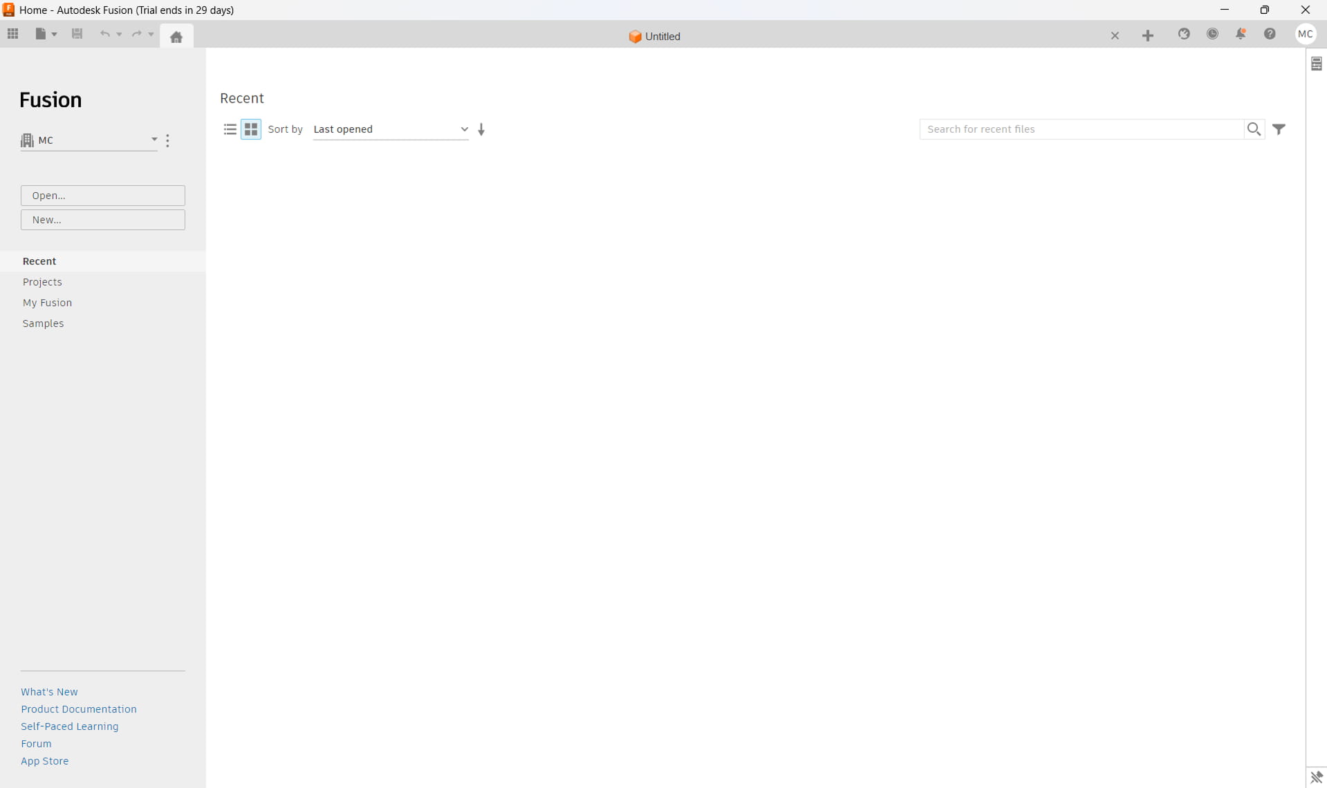
Creating a New Design
From the home screen, I clicked the New Design button located in the upper-left corner of the interface.
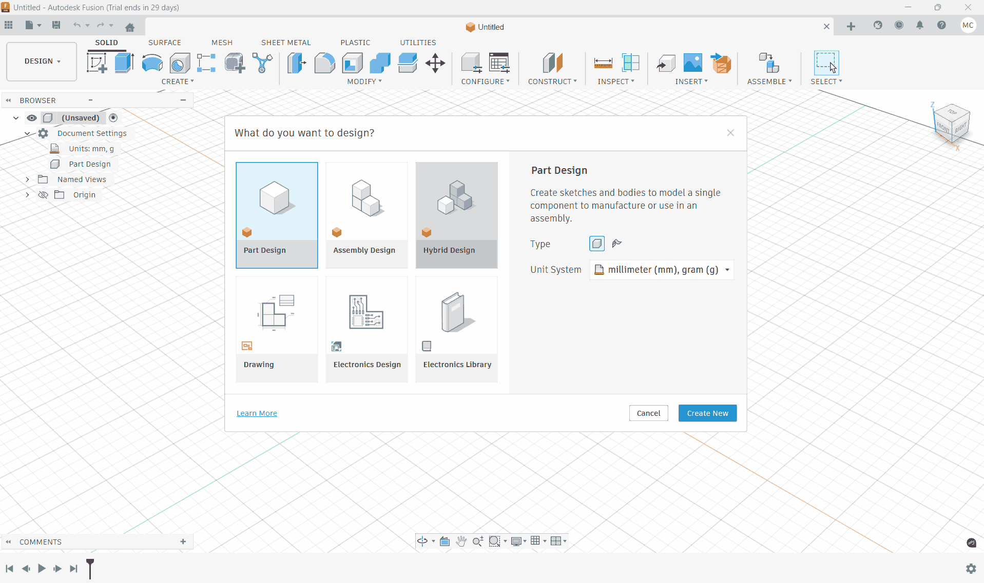
This created a new blank design file and opened the main design workspace.
Switching to Hybrid Design Mode
After creating the new design, I ensured that the workspace was set to Design mode by selecting it from the workspace dropdown menu.
I enabled the Hybrid Design environment, allowing both solid and surface modeling tools to be used together during the design process.
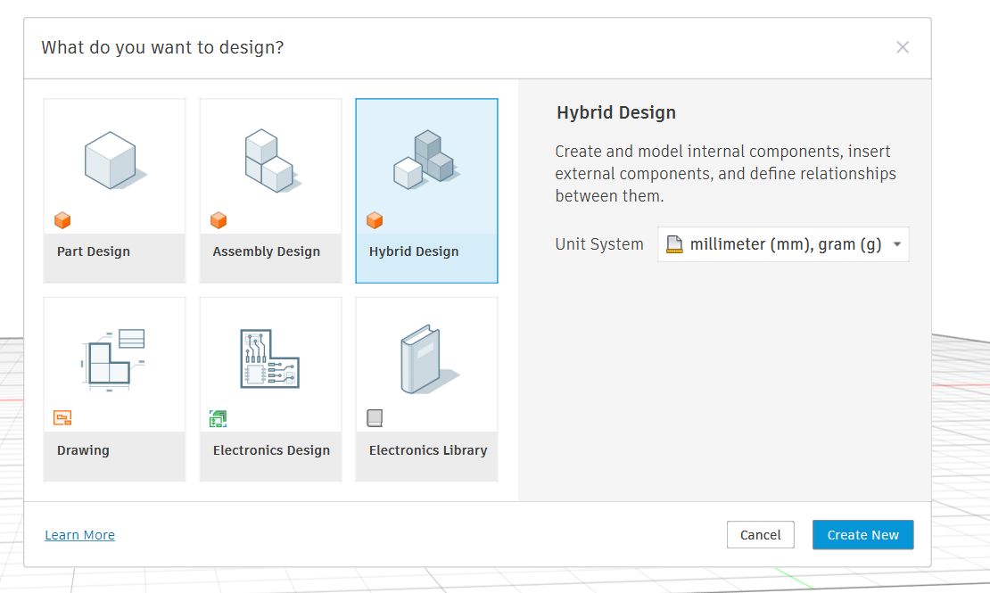
Hybrid design in Fusion (Fusion 360) means building a model by mixing multiple modeling approaches in one workflow instead of sticking to just one.
In practice, it usually combines:
- Parametric (history-based) modeling → sketches, dimensions, features
- Direct modeling → push/pull, face edits without worrying about history
- Surface modeling → complex curves and Class-A–like shapes
- Mesh / Form (T-Spline) modeling → organic, sculpted forms
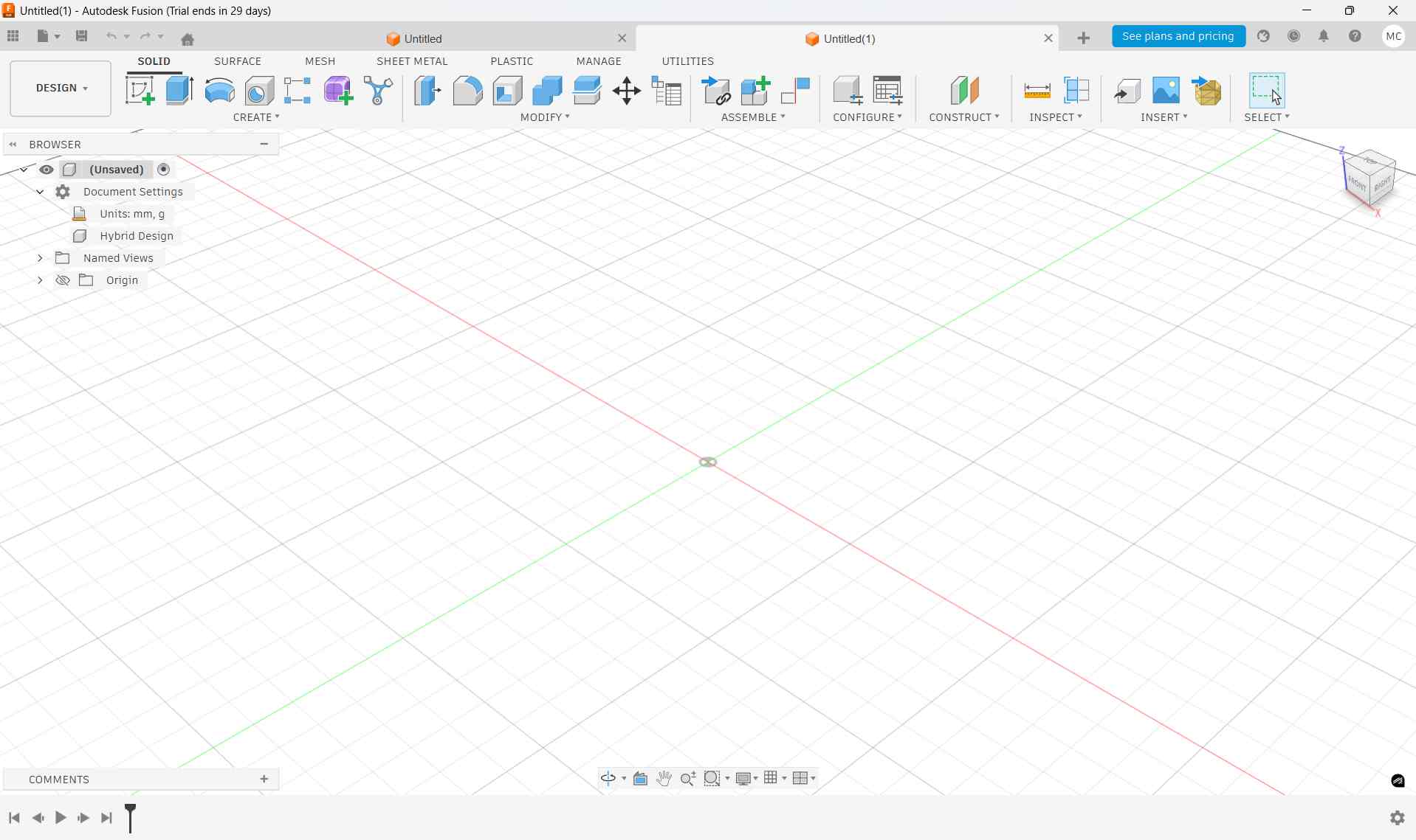
Preparing the Workspace
With the new hybrid design open, the workspace was ready for sketching and modeling the device components.
Base Body Creation
I began by clicking Create Sketch from the Create section in the Design workspace.
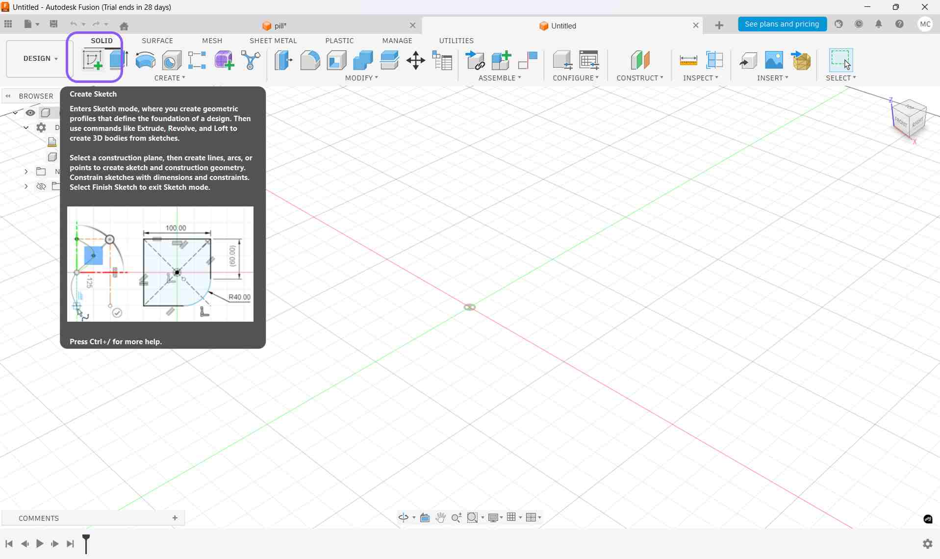
which displayed the three origin planes in the design workspace.
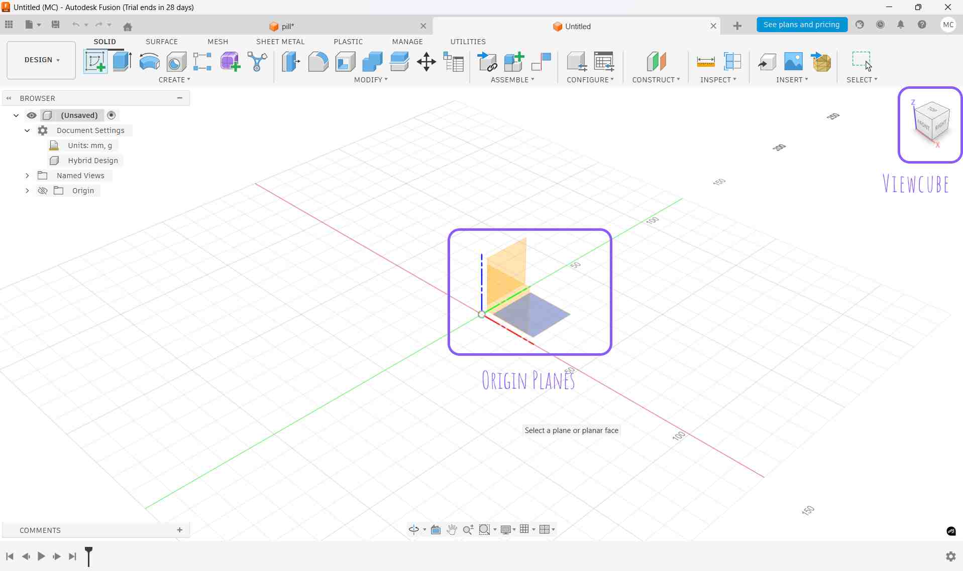
Using the ViewCube, I rotated the view until the desired reference plane was visible and clicked it, which selected the plane.
After selecting the plane, the software entered Sketch Mode.
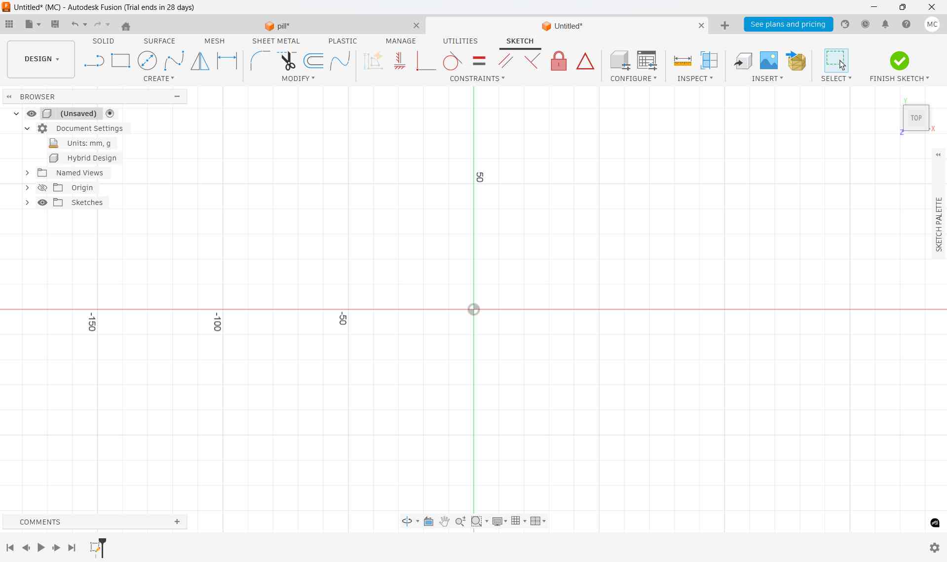
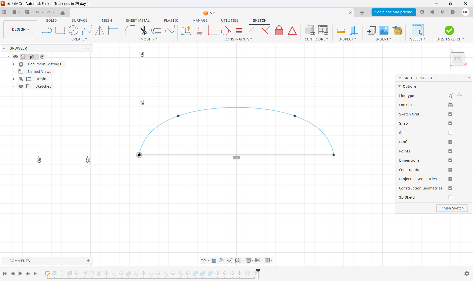
Using the Fit Point Spline Tool, I sketched a 2D profile that defines the overall pill-shaped form of the dispenser.
The sketch was carefully adjusted to ensure smooth curves and symmetry along the central axis.
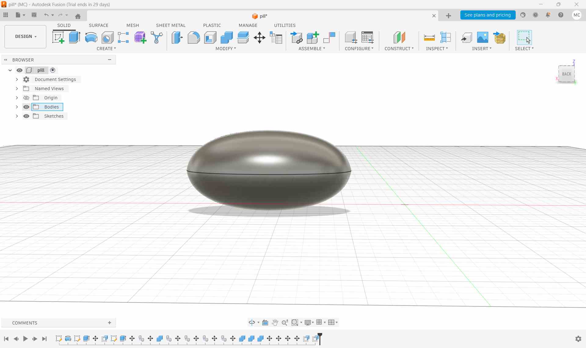
Revolving the Sketch into a 3D Body
After completing the 2D profile, I used the Revolve feature.
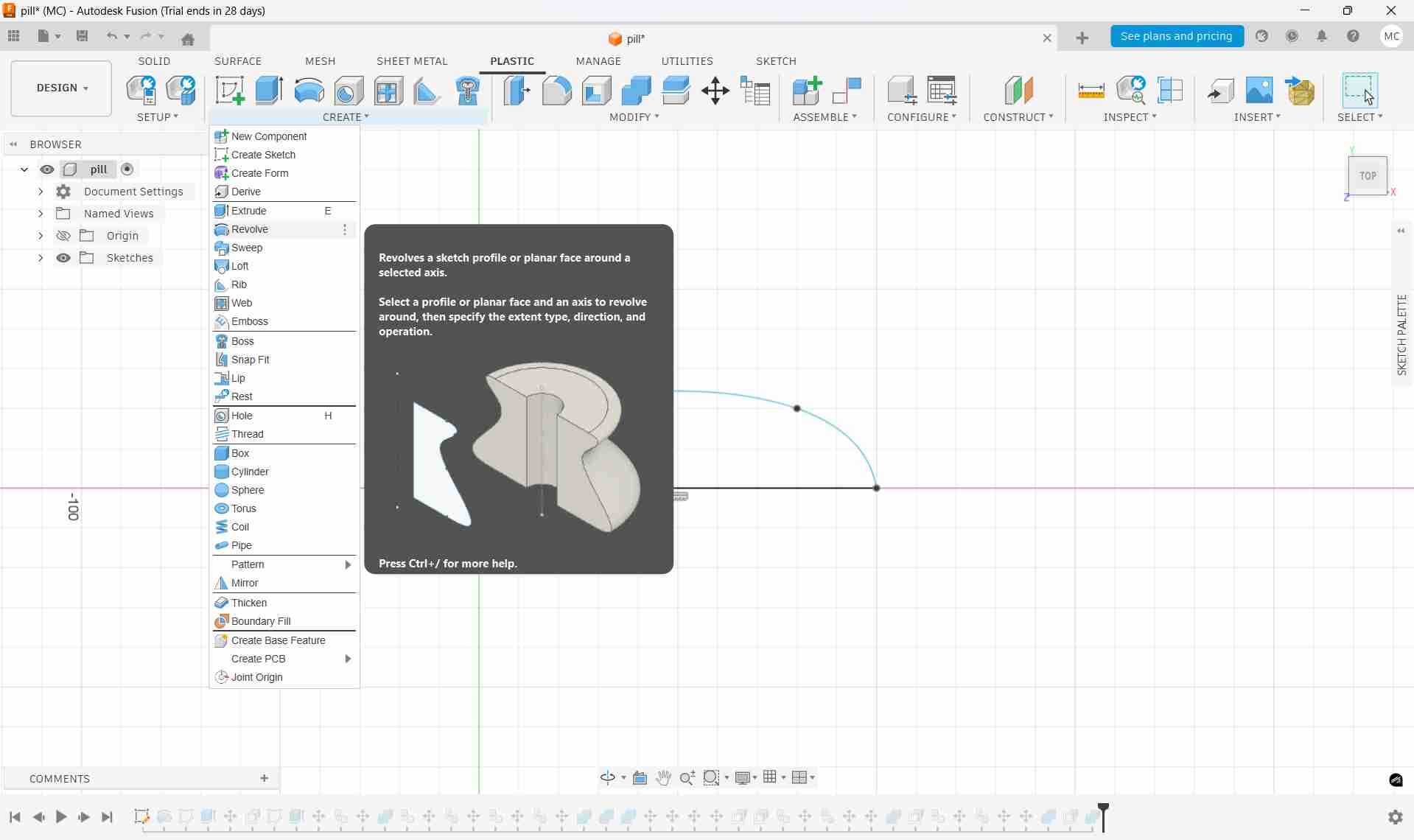
The sketch was revolved around a central axis to create a smooth and symmetrical three-dimensional base body.
This method ensured consistent curvature and an ergonomic pill-shaped form.
Incorporating Features
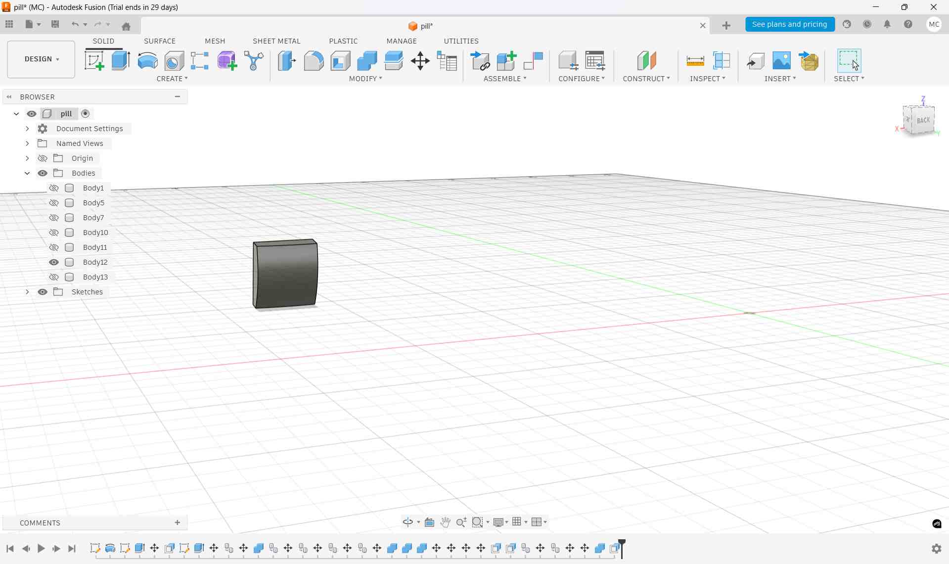
To create the LED display opening, a rectangular 2D shape was first drawn using the Rectangle tool.
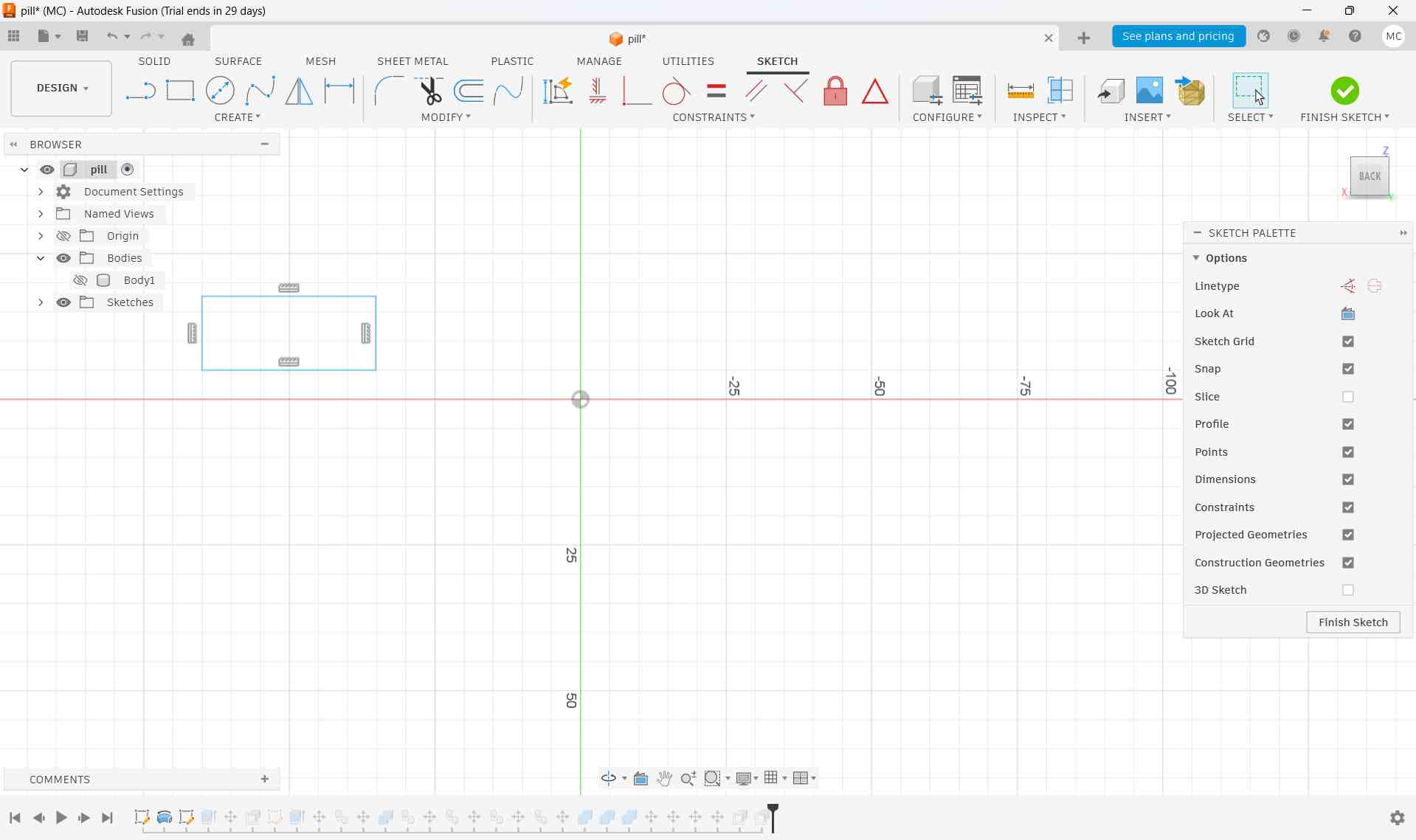
This 2D shape was then extruded to form a 3D rectangular solid.
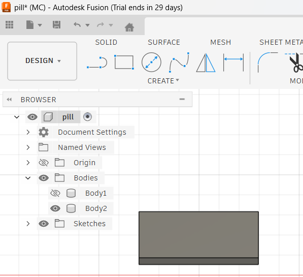
The extruded rectangular shape was positioned close to the main bottle body. Using a boolean Intersect operation from the Combine tool in the Modify section, both bodies were selected to create a clean recessed slot for the LED display.
The same process was repeated to create the medicine dispensing slot at the bottom of the bottle. A rectangular shape was created, extruded into a 3D form, positioned correctly, and used with a boolean cut to form the opening.
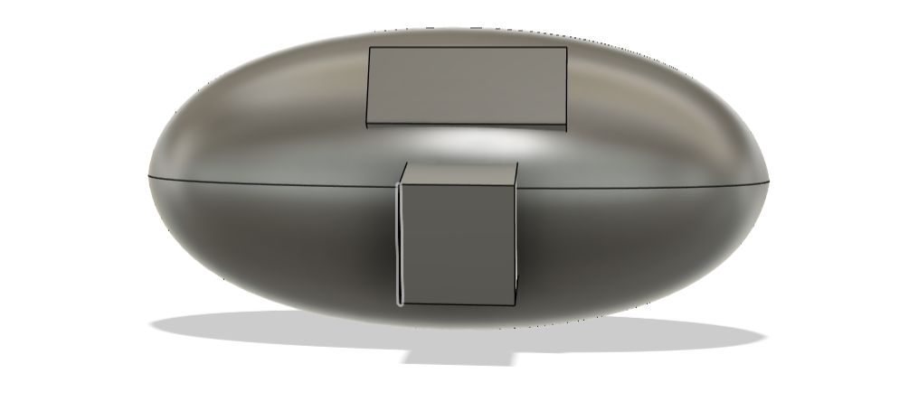
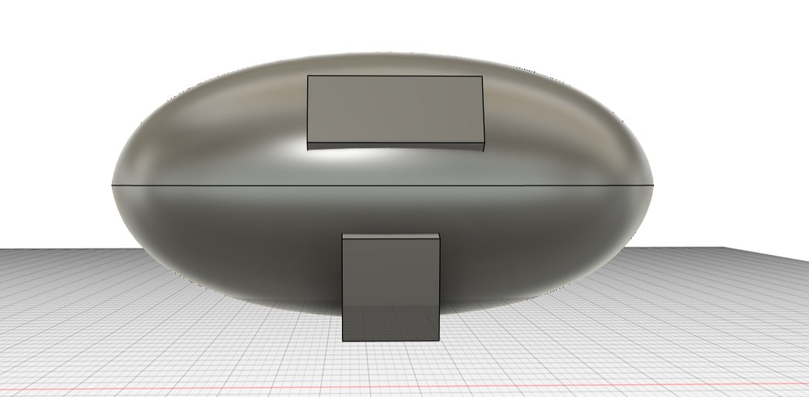
Assembly and Detailing
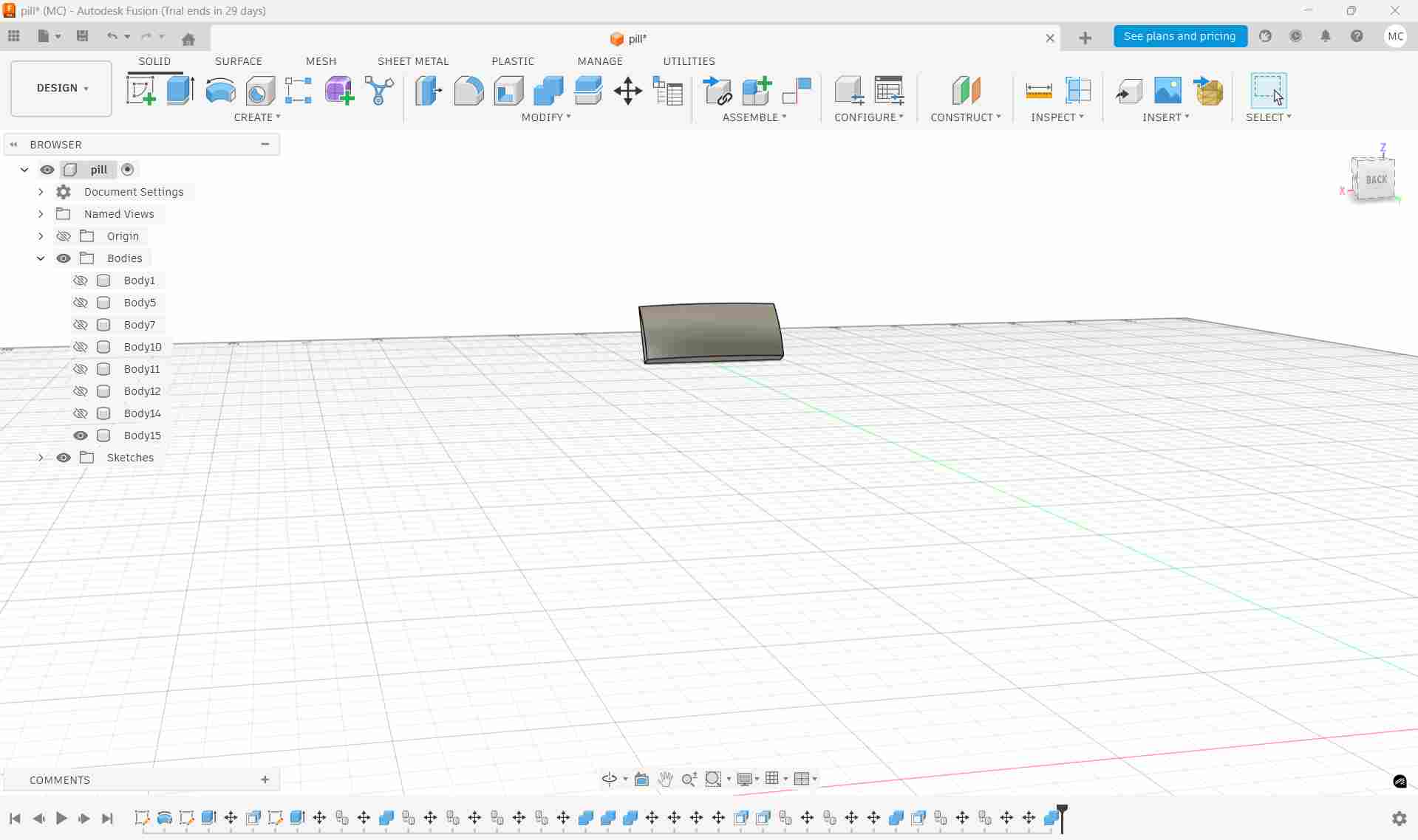
A frame for the LED display screen was modeled as a separate object and aligned carefully with the recessed display opening on the bottle body.
The medicine dispensing slot was created using the same method and carefully positioned in relation to the main bottle body.
After positioning all the individual components correctly, the Combine tool was used from the Modify section. The pill-shaped body was selected as the target body, while the two rectangular solids were chosen as the tool bodies with the operation set to Cut.
After confirming the operation, the software processed the boolean cut, resulting in cleanly defined openings for both the LED display and the medicine dispensing slot.
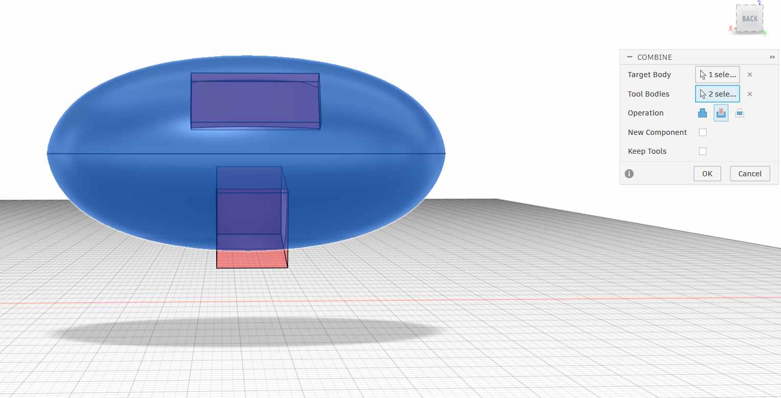
Then press 'ok'
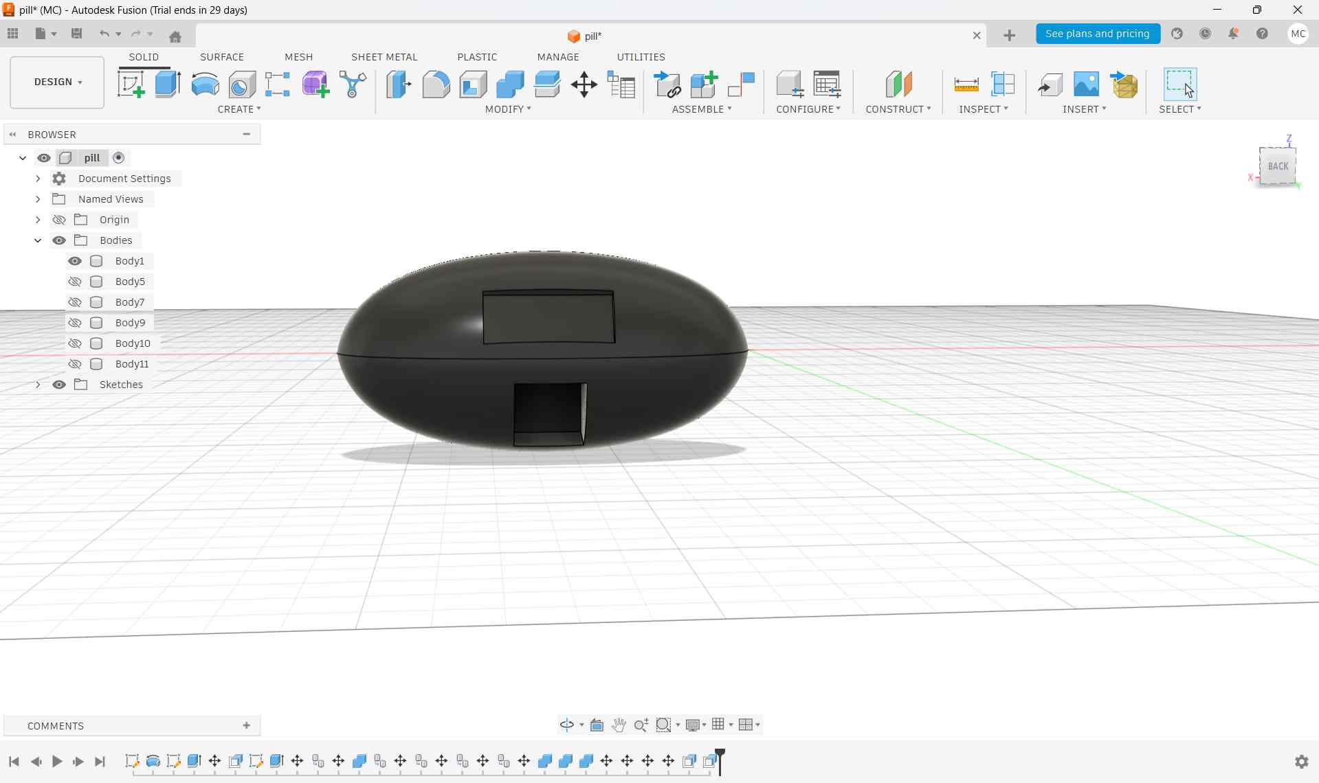
The screen frame and the slot flap were then positioned onto the main body using the Point-to-Point Transfer tool. This method was extremely helpful in accurately aligning the components, ensuring precise placement without the need for manual adjustments.
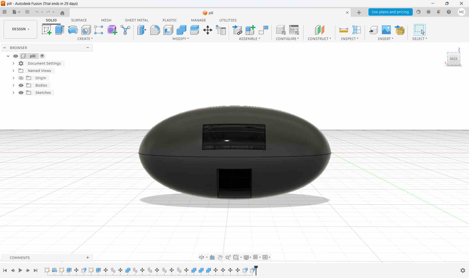
For this, go to the Move/Copy tool in the Modify section. In the window that appears, choose bodies, then click on the body to be moved. Next, select the fourth option which says 'Point to Point' and click on the 'Create Copy checkbox'. This allows precise alignment of components by matching specific points between objects.
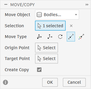
This was the final design
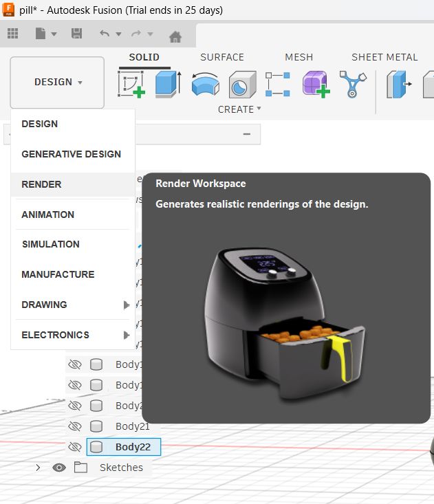
Rendering the Final Design
After completing the 3d design, I switched to the render workspace in Fusion 360.
I clicked 'a' to open up the appearence tab. You can also click the Appearence icon on the top toolbar.
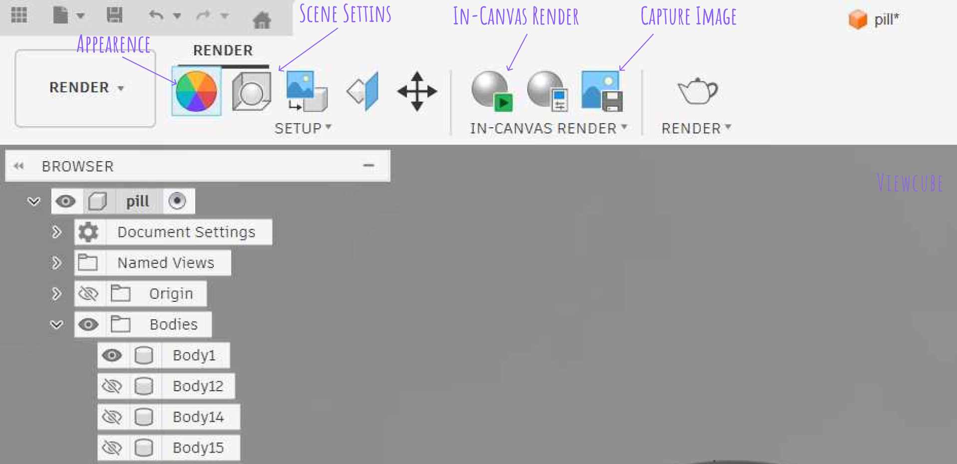
This is the window that opens up.
Inside this appearence library, I had fun switching between different materails for my final look. i could even make the material glass:-D
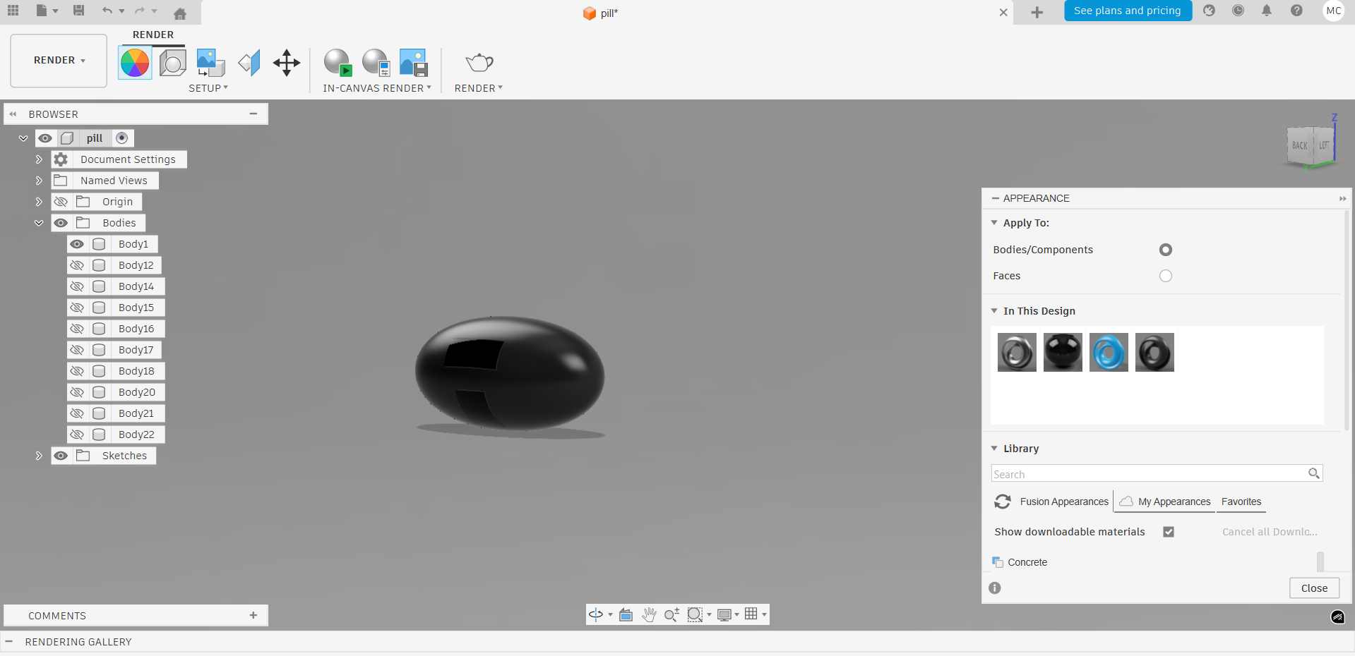
To give it a background, i clicked on the Scene Settings and went to the Environmental Library. From here, I could chose a background for my design.
After the design was finalised, I clicked the In-Canvas Render button. This began rendering the design.

This image was captured using the Capture Image tool in the toolbar.
Animation
After the rendering was complete, the final 3D model was exported in FBX format.
For this, I went to File, then Export, and selected FBX as the export format. This was done so that the model could be imported into other software like Blender for further editing or animation.
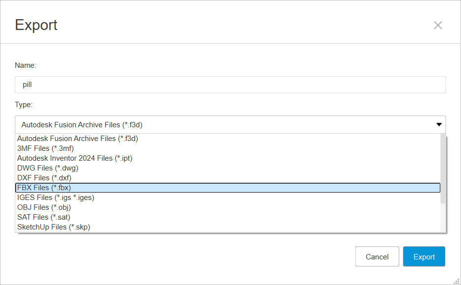
Why FBX works best:
- Blender imports FBX reliably without scaling issues
- It preserves object hierarchy and transformations
- Materials and basic appearances are transferred better than STL
- It’s ideal for animation workflows
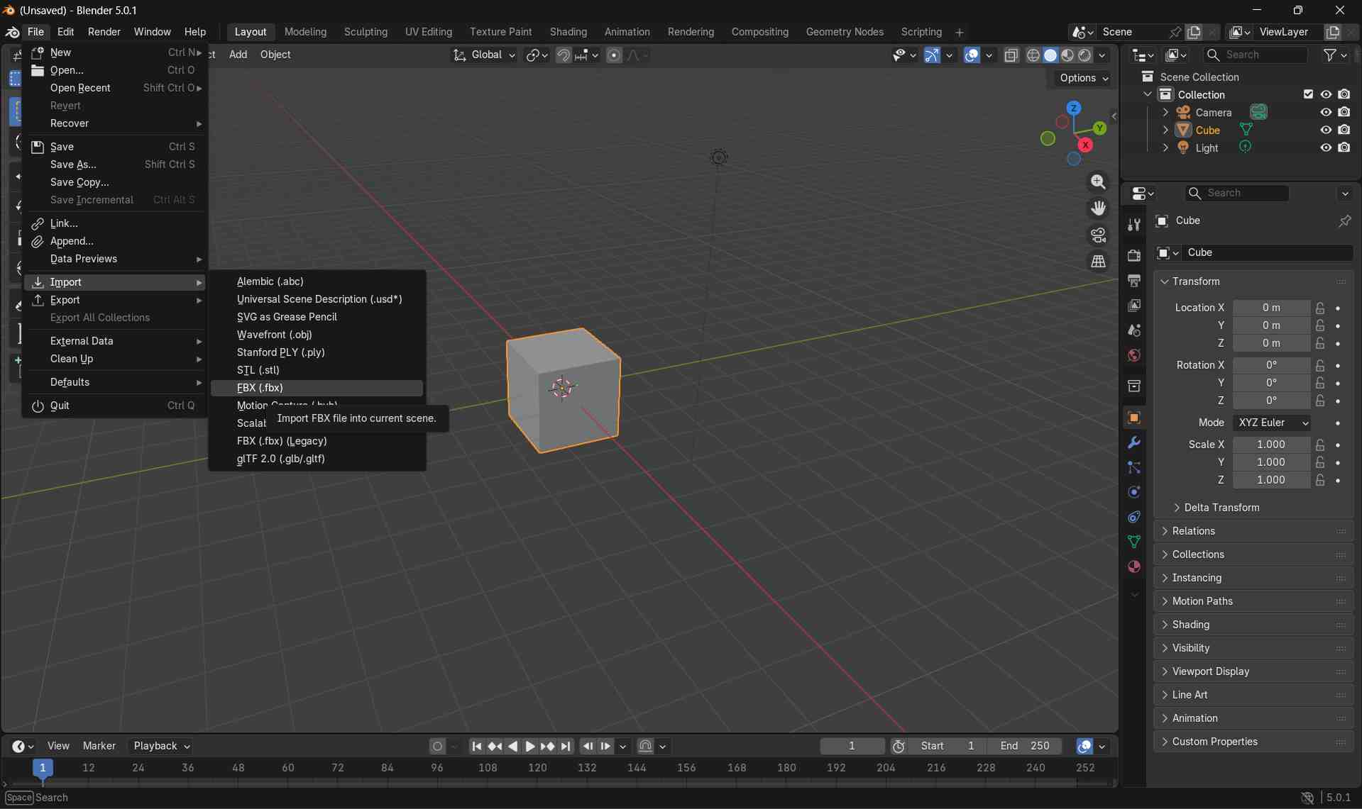
Then I chose Blender as my animation software.
In Blender, I went to File, Import, then chose the FBX format. This opened the Pill Design in Blender. I deleted the Cube body that opens up in Blender and focused on my Design.
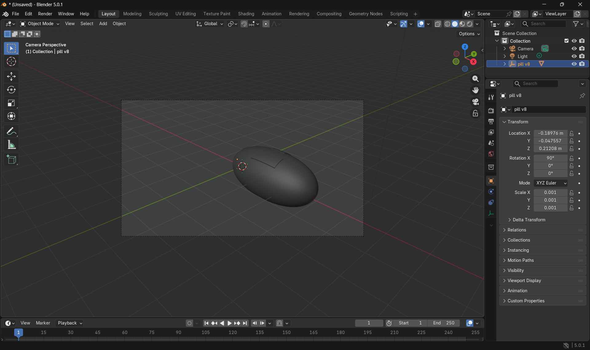
The design was too small, so I clicked my body,and scaled it up by pressing 's' and dragging my mouse.
Then wanted to kknow if my body was large enough to animate. So, I pressed'0' to switch to camera view. I could see that the body was large enough to be seen in the camera view, so I was ready to animate.
I have given a detailed instruction on how to animate an object in Blender below. You can read that to know how I animated my pill design.
Here is the final video
Blender
View My Blender TutorialFor the 3D modeling of my possible final project, I used Blender to develop the initial form and surface refinement of a bottle-like enclosure. The objective was to explore the overall shape, proportions, and curvature while preparing a clean and smooth 3D model suitable for further detailing and digital fabrication.
Blender is a free and open-source 3D creation software used for modeling, sculpting, rendering, animation, and simulation. It is widely adopted in product design, visualization, and digital fabrication workflows due to its powerful polygon modeling tools and non-destructive modifier system.
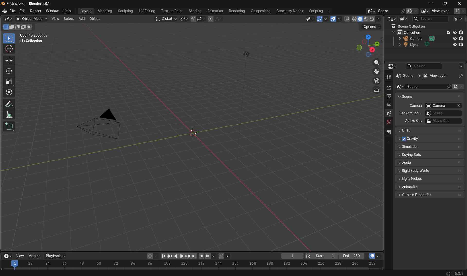
Opening Blender
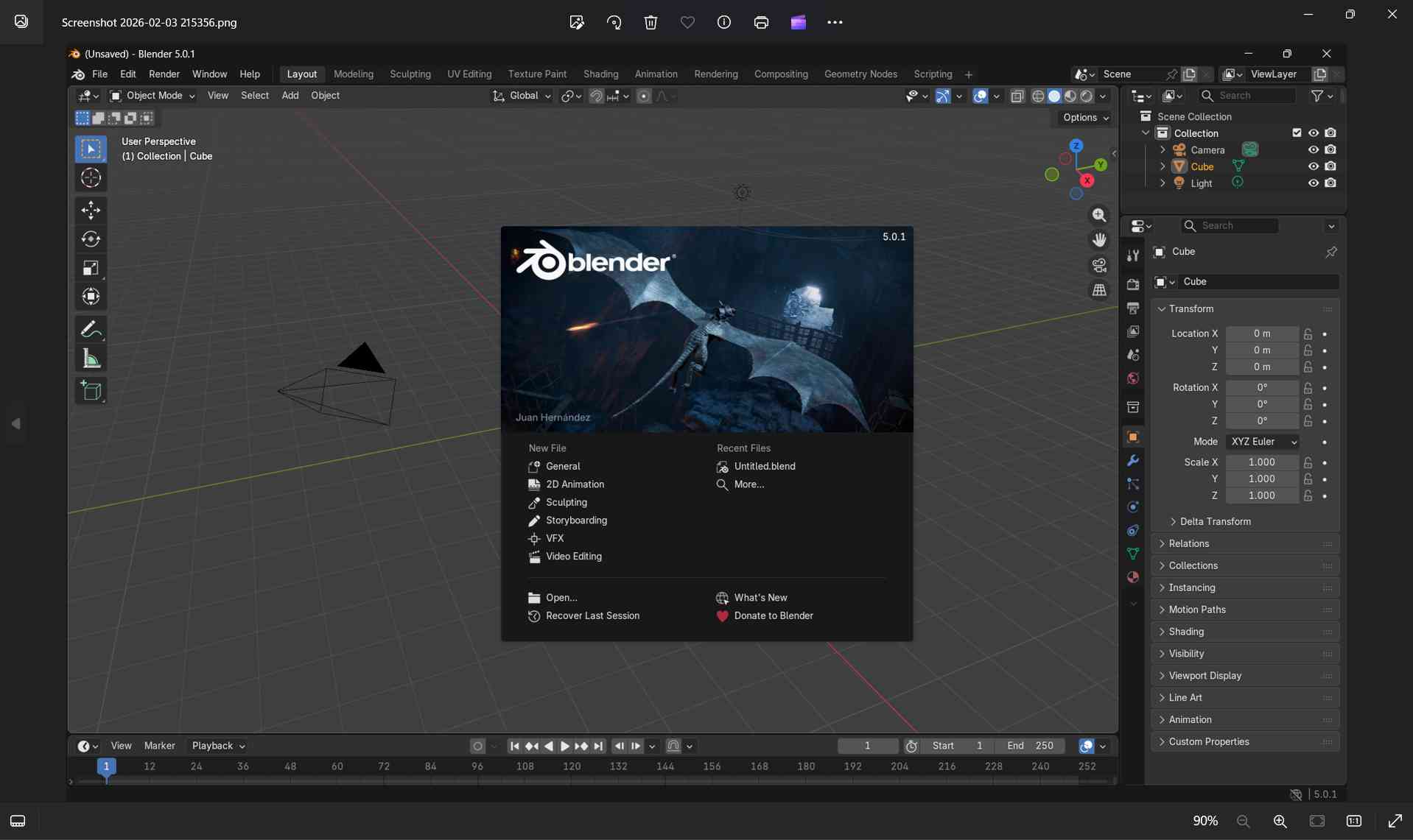
I launched Blender from the desktop application.
Upon opening, Blender loaded the default General startup file, which includes a cube, camera, and light.
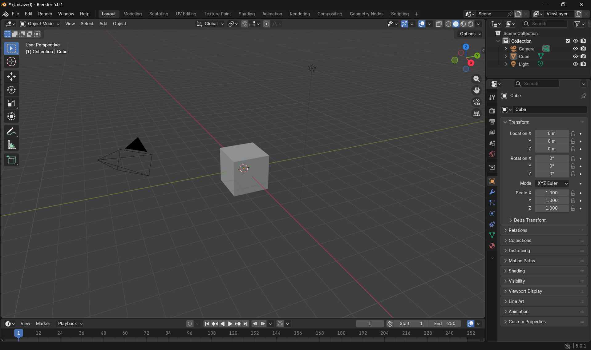
Preparing the Workspace
To start with a clean workspace, I selected the default cube and deleted it by pressing X and confirming the action.
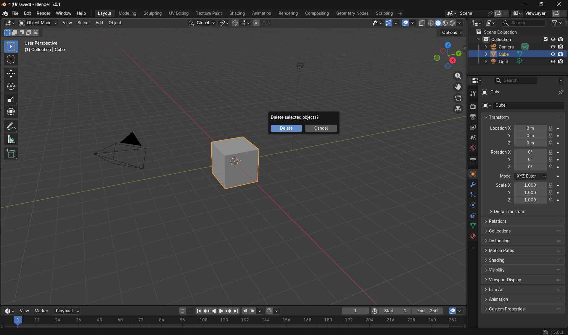
This cleared the scene and prepared the viewport for adding new geometry.
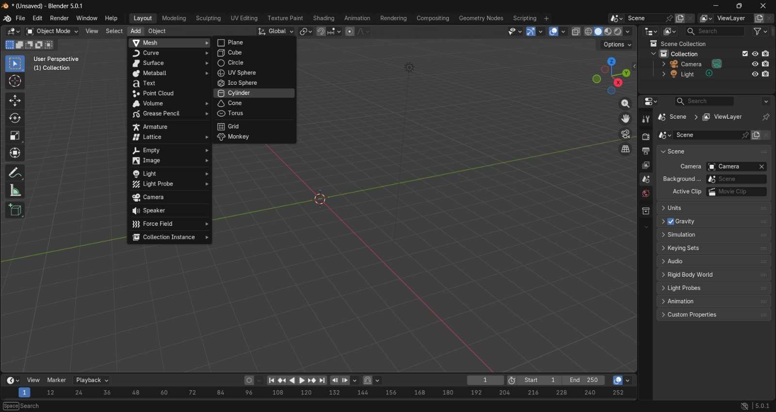
Adding the Base Geometry
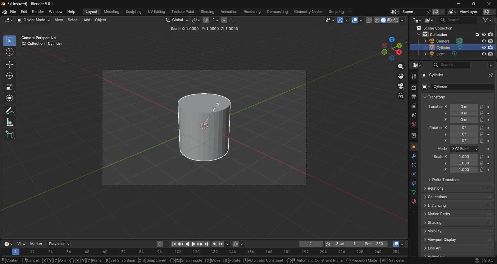
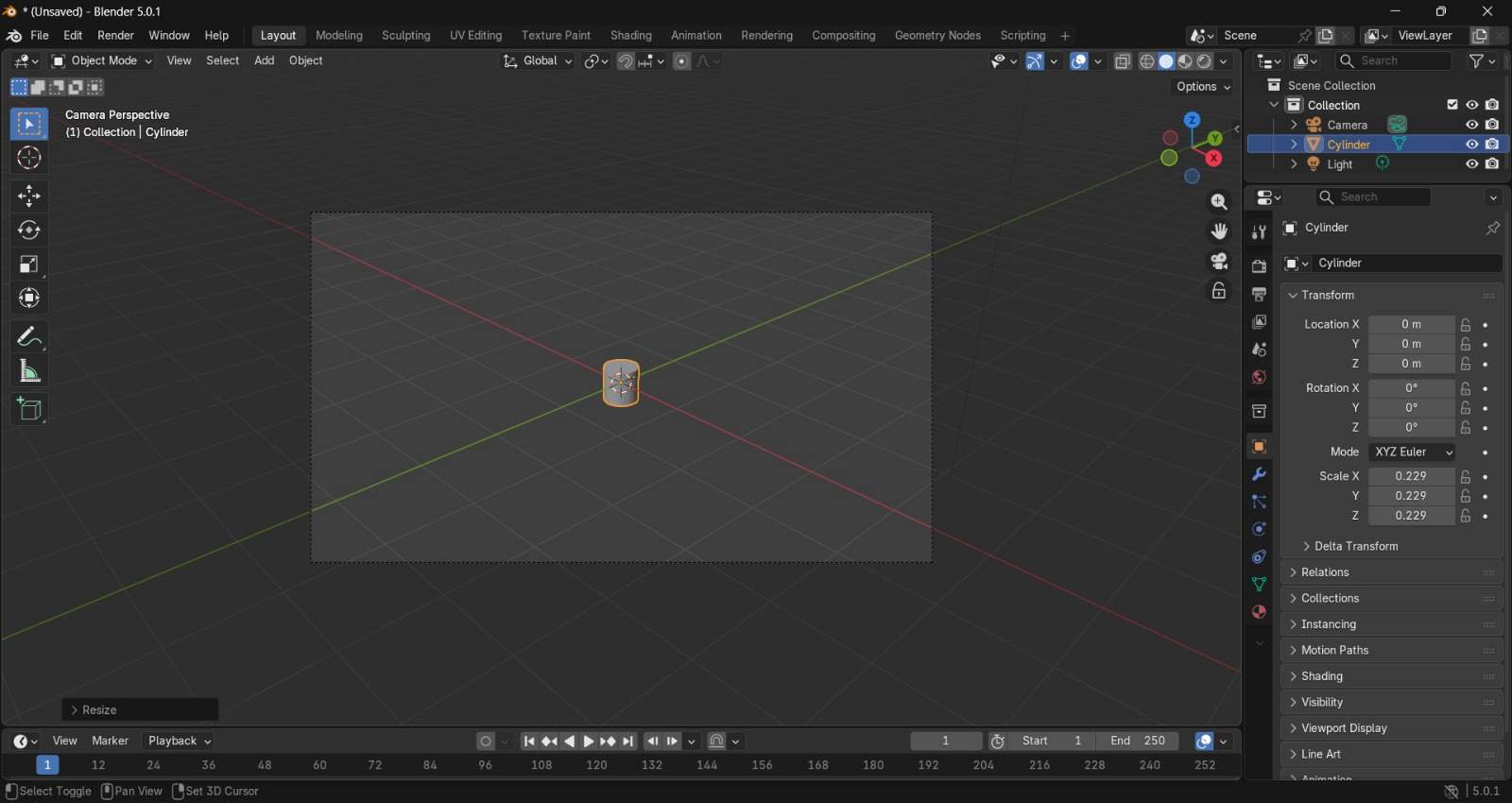
I added a base cylinder by navigating to Add → Mesh → Cylinder.
After placing the cylinder, I resized it by pressing s and scaling it down to an appropriate size for the bottle base.
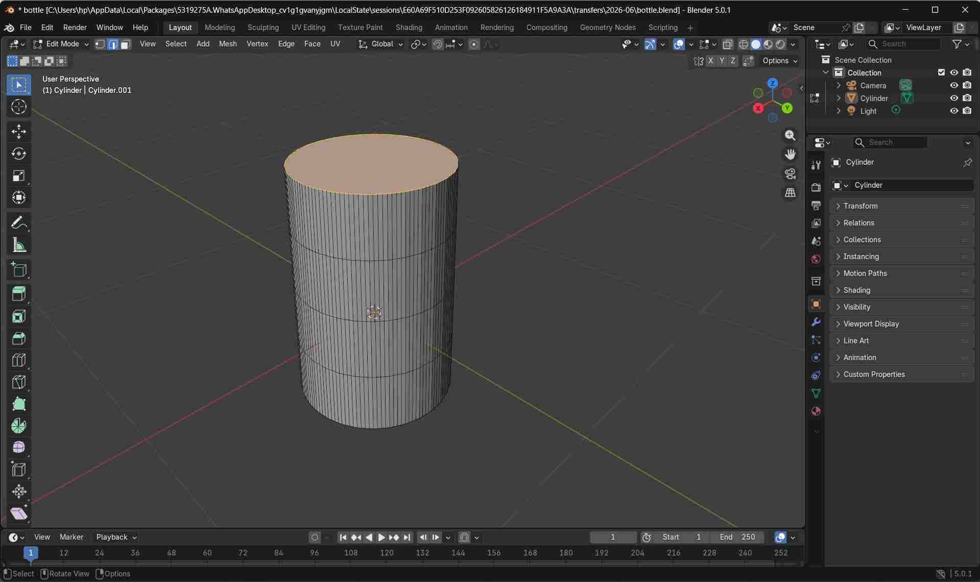
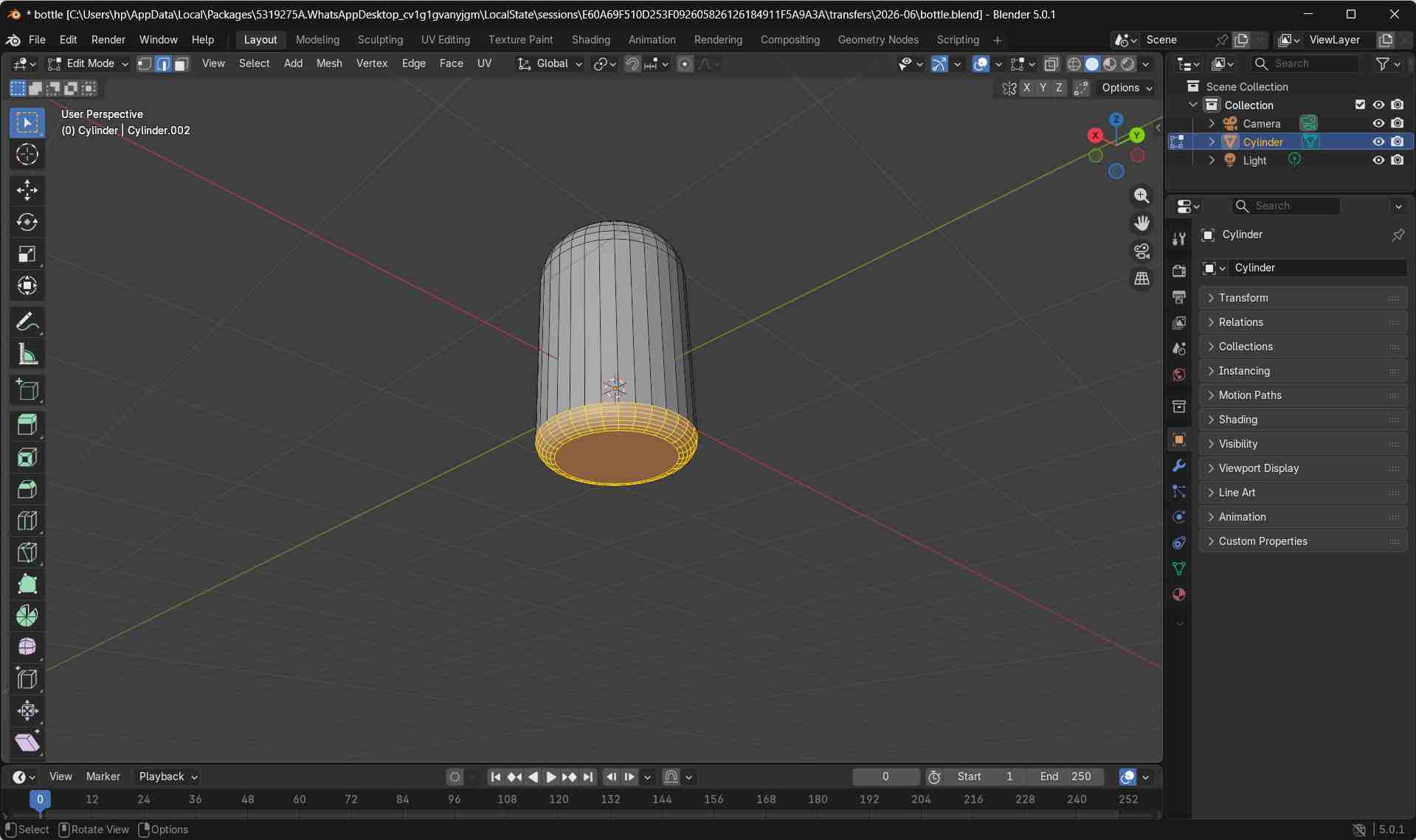
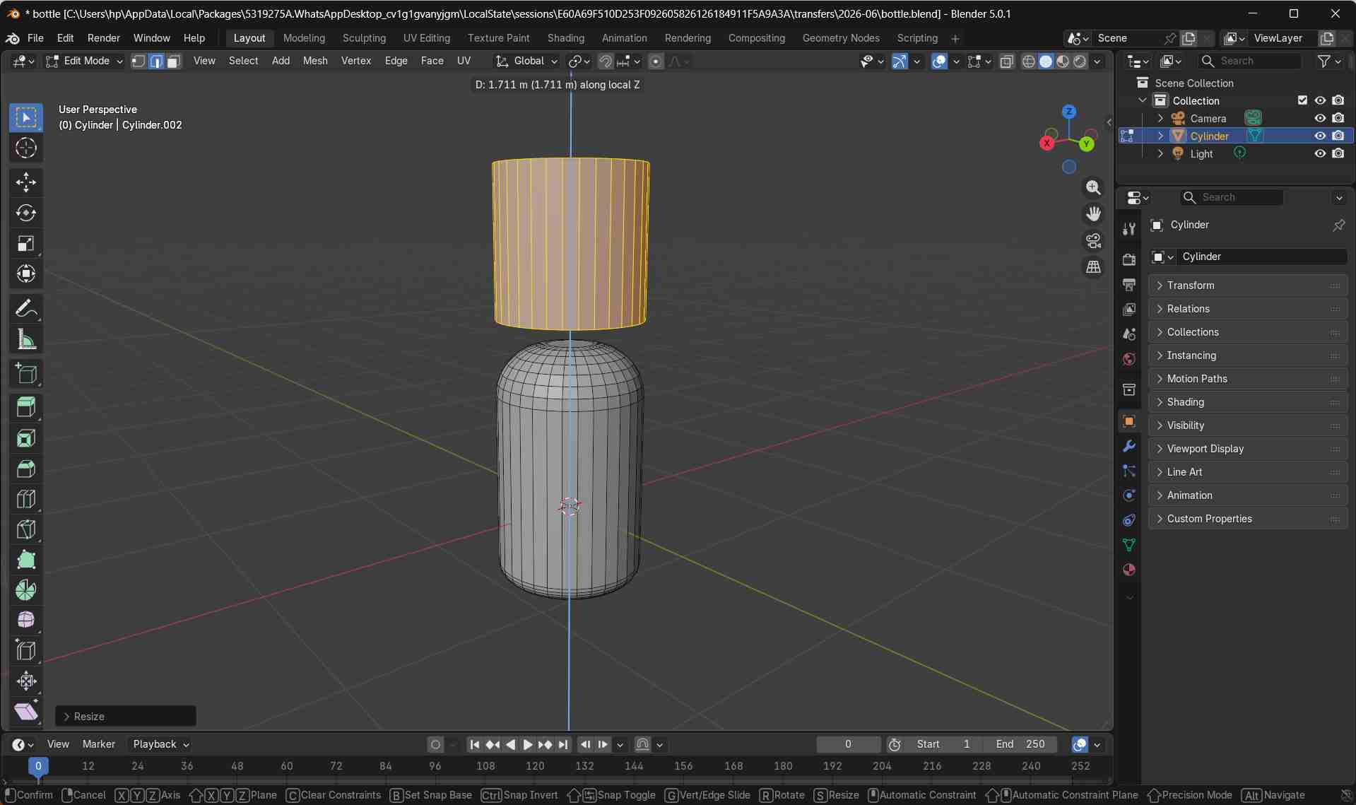
Shaping the Body in Edit Mode
I pressed Tab to switch from Object Mode to Edit Mode in order to modify the mesh geometry.
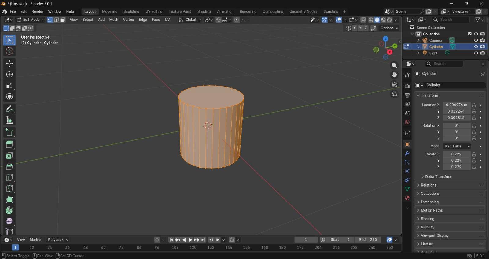
In Edit Mode, I selected the top face of the cylinder and pressed G followed by z + Up Arrow to move the geometry upward strictly along the Z-axis.
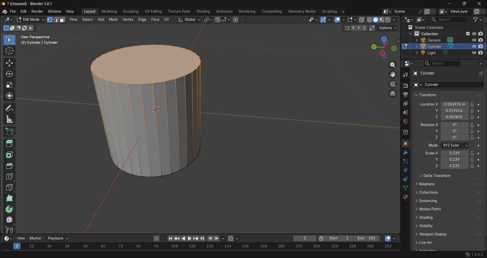
This action extended the upper section of the cylinder, defining the overall height and basic silhouette of the dispenser.
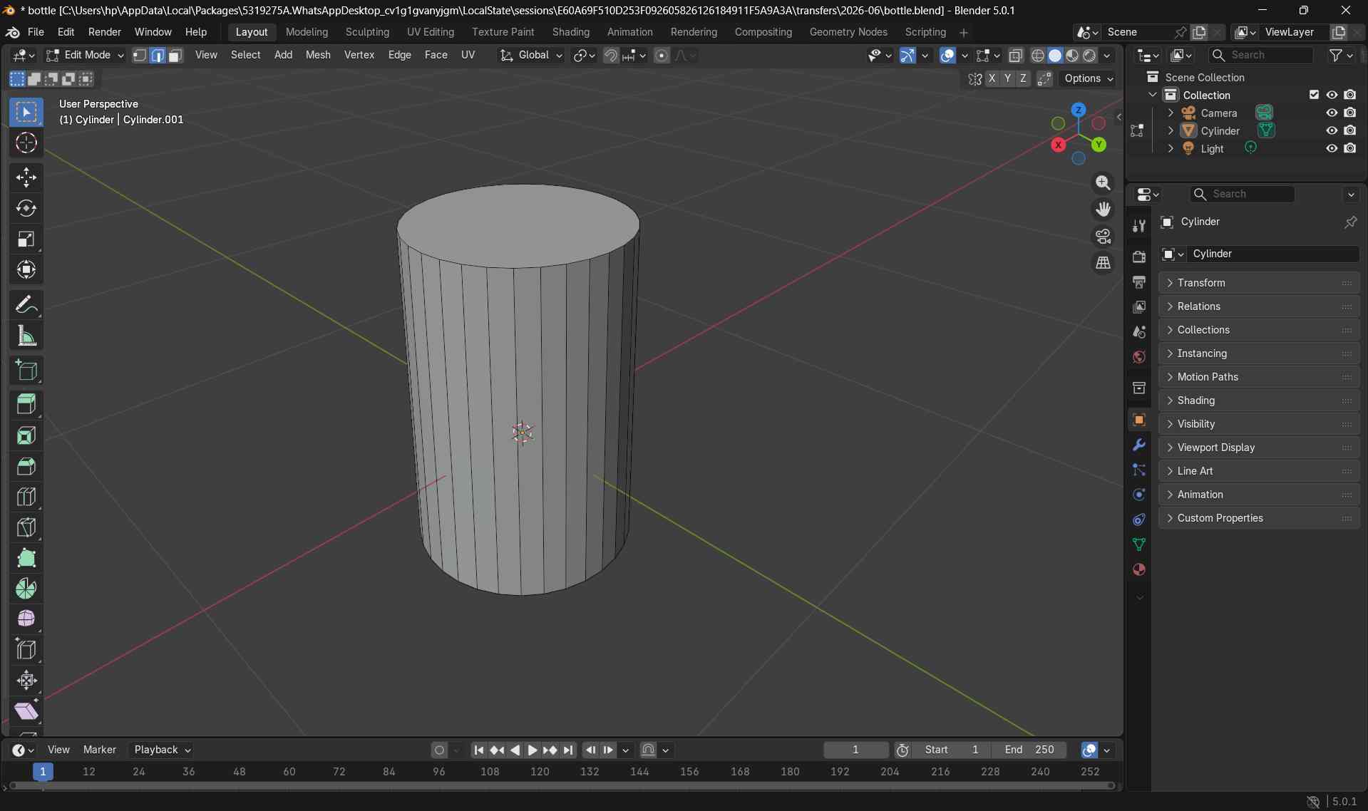
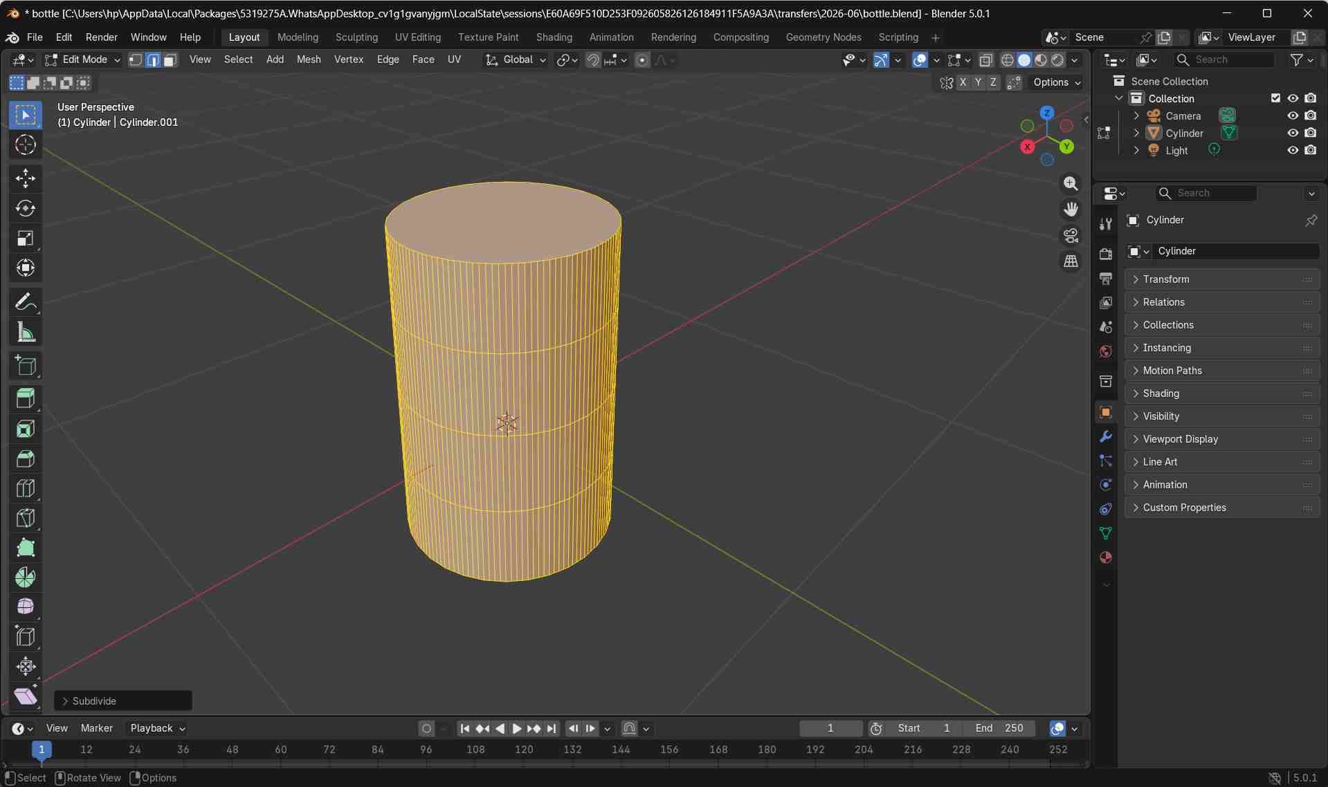
Refining Geometry for Realistic Curves
To achieve realistic rounded surfaces, the mesh geometry was further refined.
In Edit Mode, I selected all geometry using a, then right-clicked and chose Subdivide.
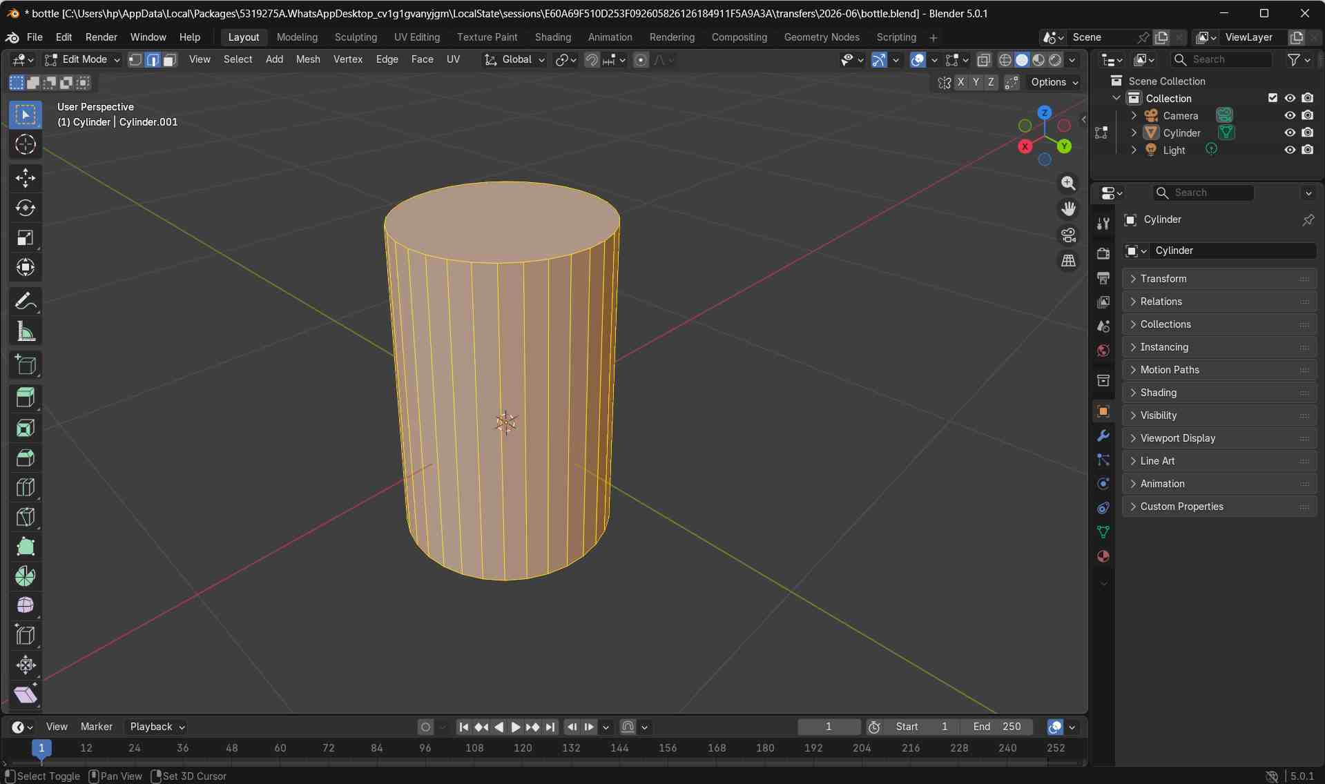
The number of cuts was increased to add more geometry, allowing smoother curvature along the body.
Why Subdivision Is Used in Blender
In Blender, 3D models are made using flat surfaces called faces.
When a basic shape like a cylinder is created, it has only a small number of faces. This makes the object look blocky instead of smooth.
Subdivision is used to add more faces to the mesh.
By adding more geometry, the shape can bend and curve smoothly. This is important when modeling rounded objects such as bottles, containers, and product enclosures.
In short, subdivision helps create smooth, realistic curves instead of sharp and flat surfaces.
Beveling Sharp Edges
Since real-world bottles do not have sharp edges, beveling was applied to the rim.
In Edit Mode, I activated Edge Select mode by pressing 2.
Edge Select Mode
Edge Select Mode is used in Blender to select and edit the edges of a mesh.
In Blender, every 3D object is made of three basic parts:
- Vertices – points
- Edges – lines connecting points
- Faces – flat surfaces
Edge Select Mode is used to select and edit the edges (lines) of a mesh.
Edge Select Mode is mainly used when you want to:
- Round sharp edges using bevel
- Select edge loops around a bottle or cylinder
- Control how a shape curves
- Prepare edges for smoothing or subdivision
For example, when modeling a bottle:
Shortcut Keys
- 1 – Vertex Select
- 2 – Edge Select
- 3 – Face Select
I selected the top edge loop using Alt + Click.
Finally, I applied a bevel by pressing Ctrl + B to round the edge.
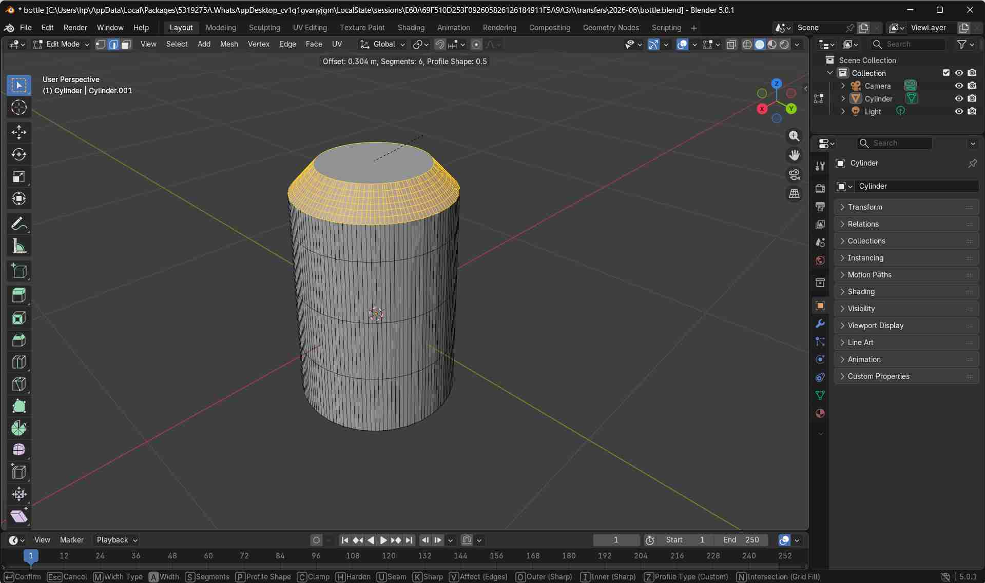
Additional bevel segments were added using the scroll wheel to create a smooth, rounded lip.
While using the Bevel tool (Ctrl + B), the mouse scroll wheel was used to increase or decrease the number of bevel segments.
Scrolling up adds more segments, which divides the bevel into smaller steps and creates a smoother, rounded curve.
Scrolling down reduces the number of segments, resulting in a sharper and more angular edge.
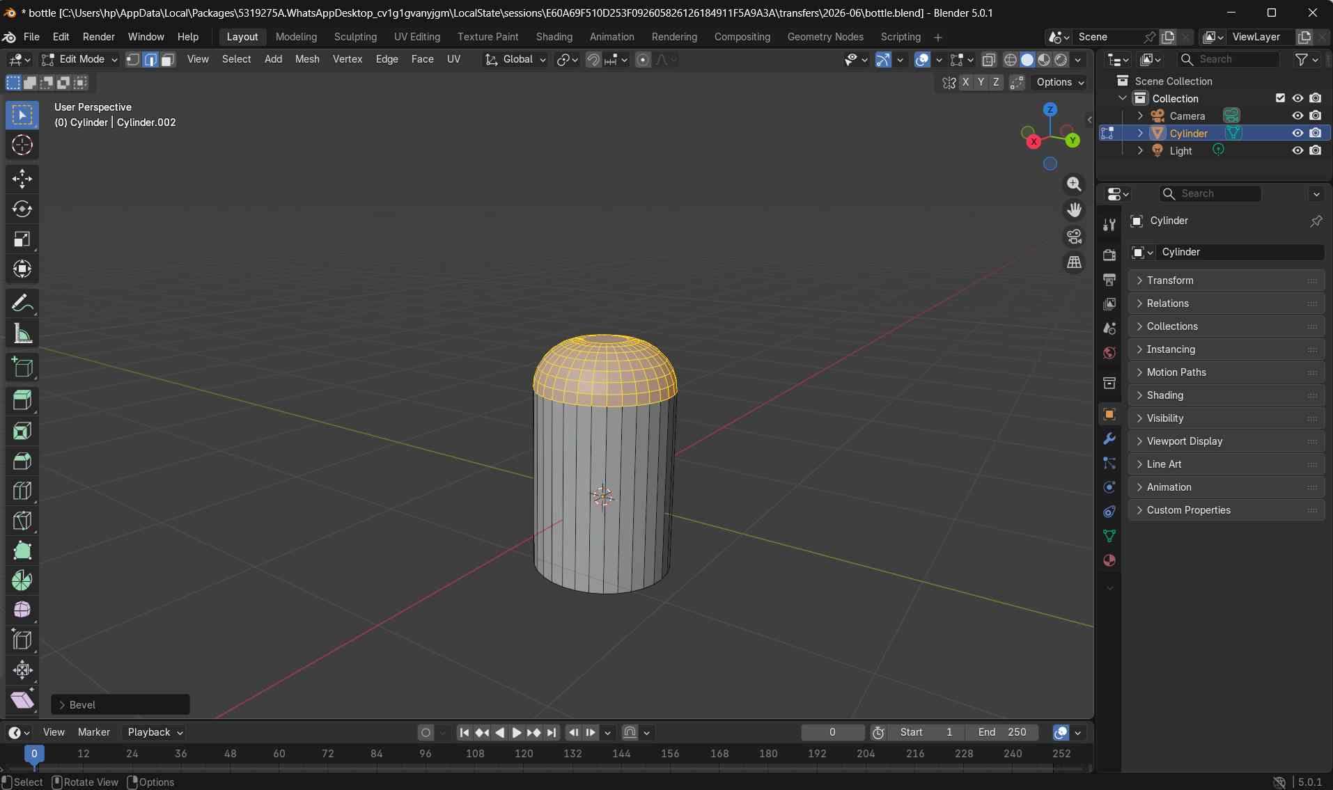
The Bevel tool was also applied to the bottom edge of the model to smoothen the lower rim and remove sharp transitions.
This ensured that the base of the bottle had a rounded and realistic finish.
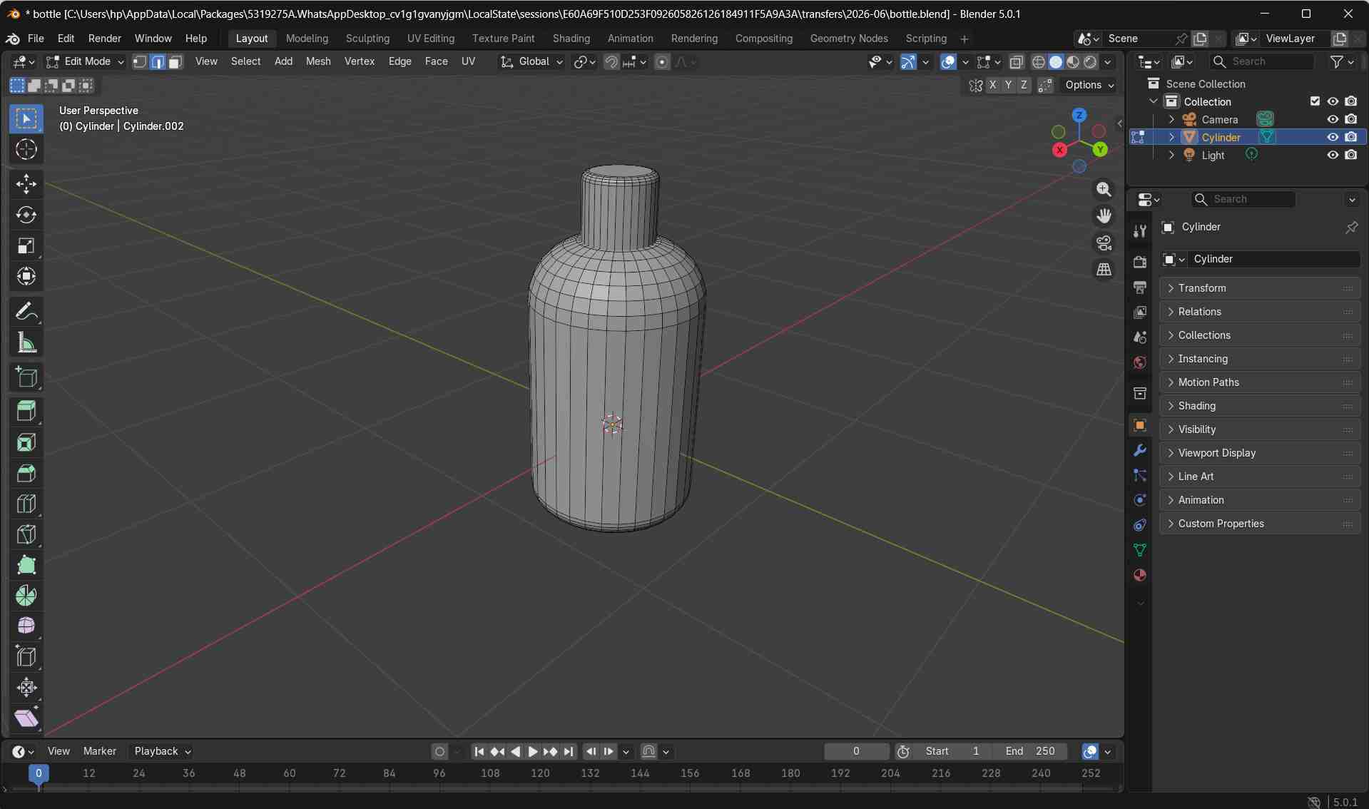
Creating the Bottle Cap
To create the bottle cap, a new cylindrical mesh was added by navigating to Add → Mesh → Cylinder.
The newly added cylinder was resized using the S key and adjusted to match the proportions of the bottle cap.
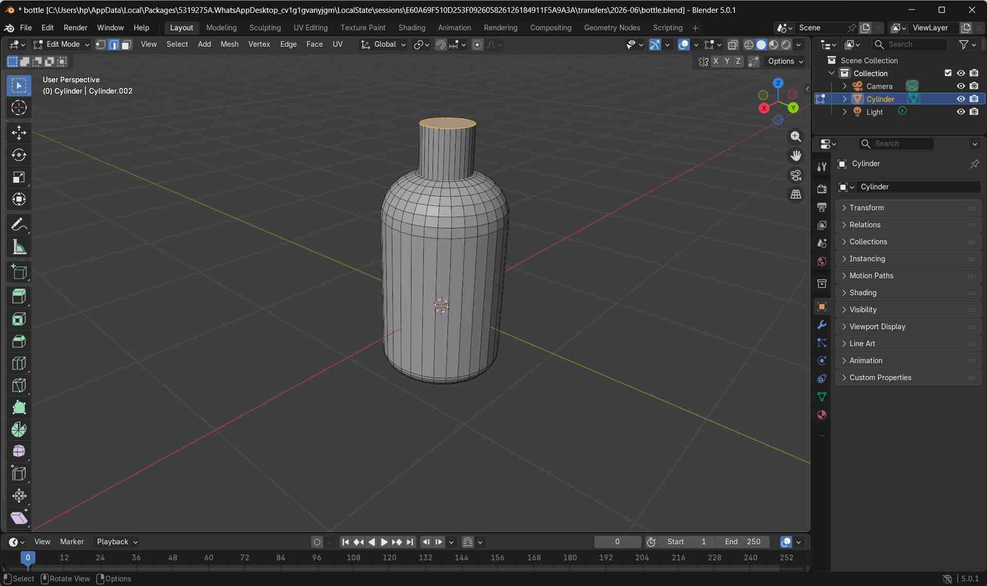
With the bottle cap modeled and aligned correctly, the bottle design was considered complete.
Adding a Simple Animation
To create a simple animation, I first ensured that the object was in Object Mode by pressing the Tab. Object Mode is required to move the entire bottle as a single object.
Next, I switched the workspace to Animation using the workspace tabs at the top of the Blender interface. This opens the Timeline required for adding keyframes.
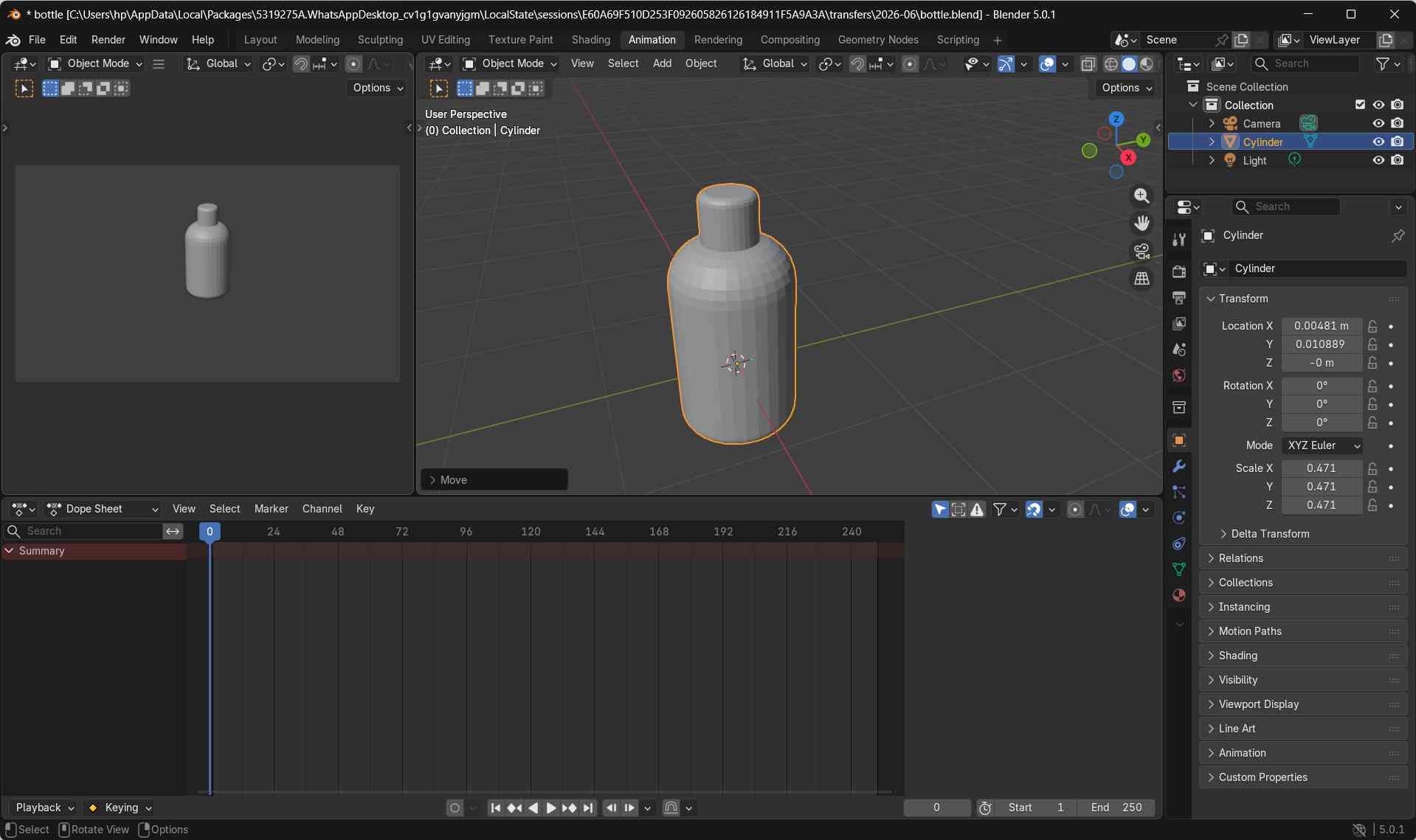
With the bottle object selected and the timeline playhead placed at the starting frame, I positioned the bottle where it should appear at the beginning of the animation and pressed i to confirm and store this location.
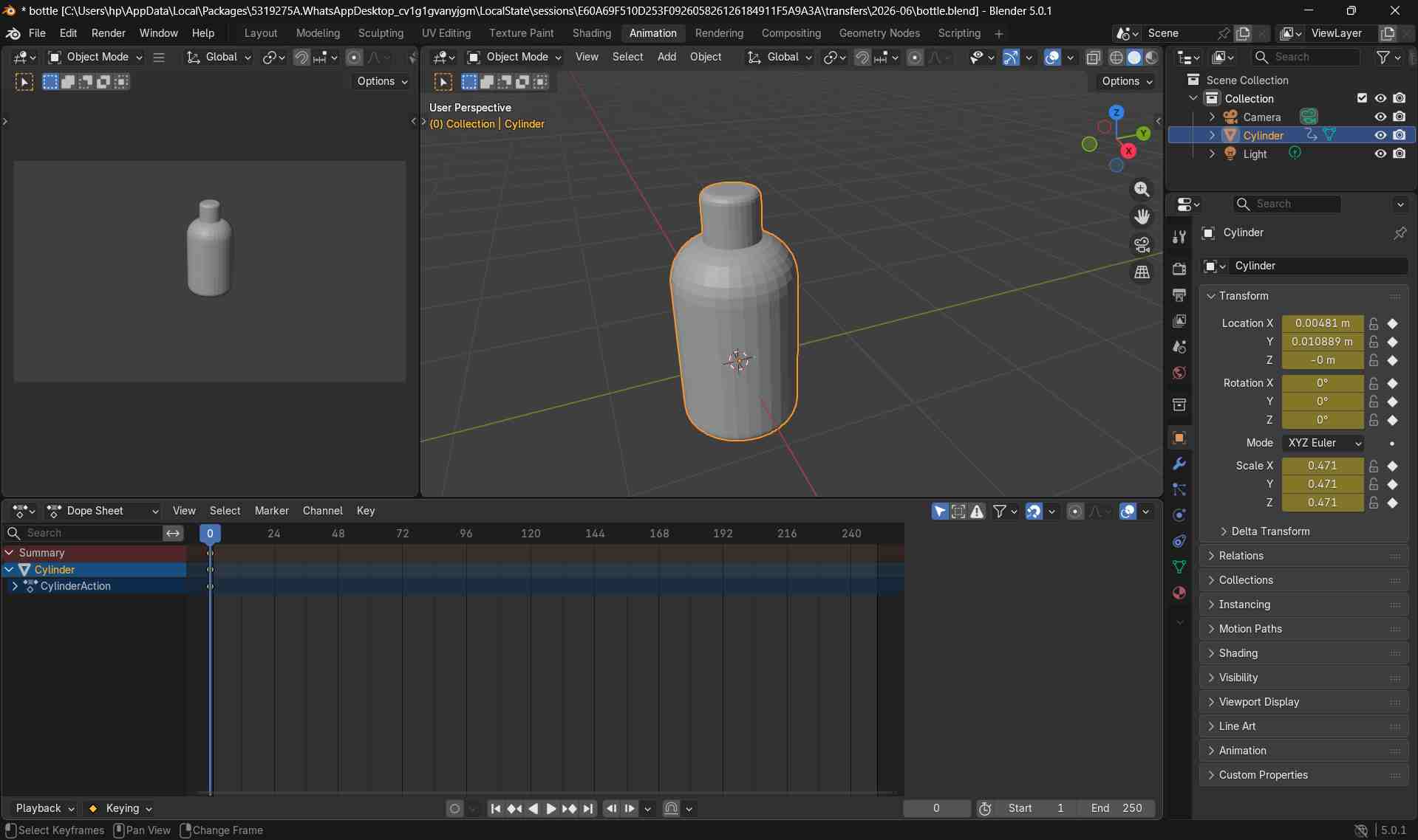
I then moved the timeline to a later frame, pressed g, and dragged the bottle to a new position.
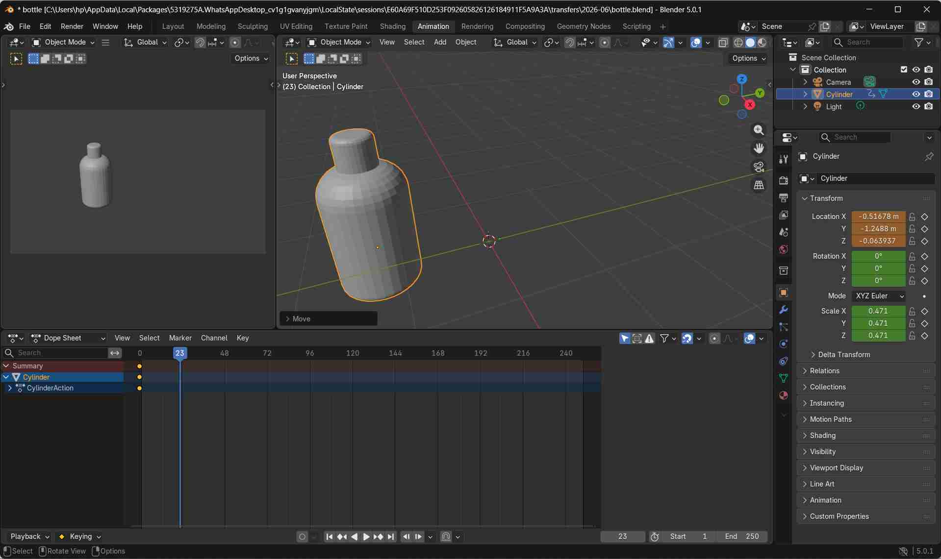
After repositioning the bottle, I pressed i again to store the final position.
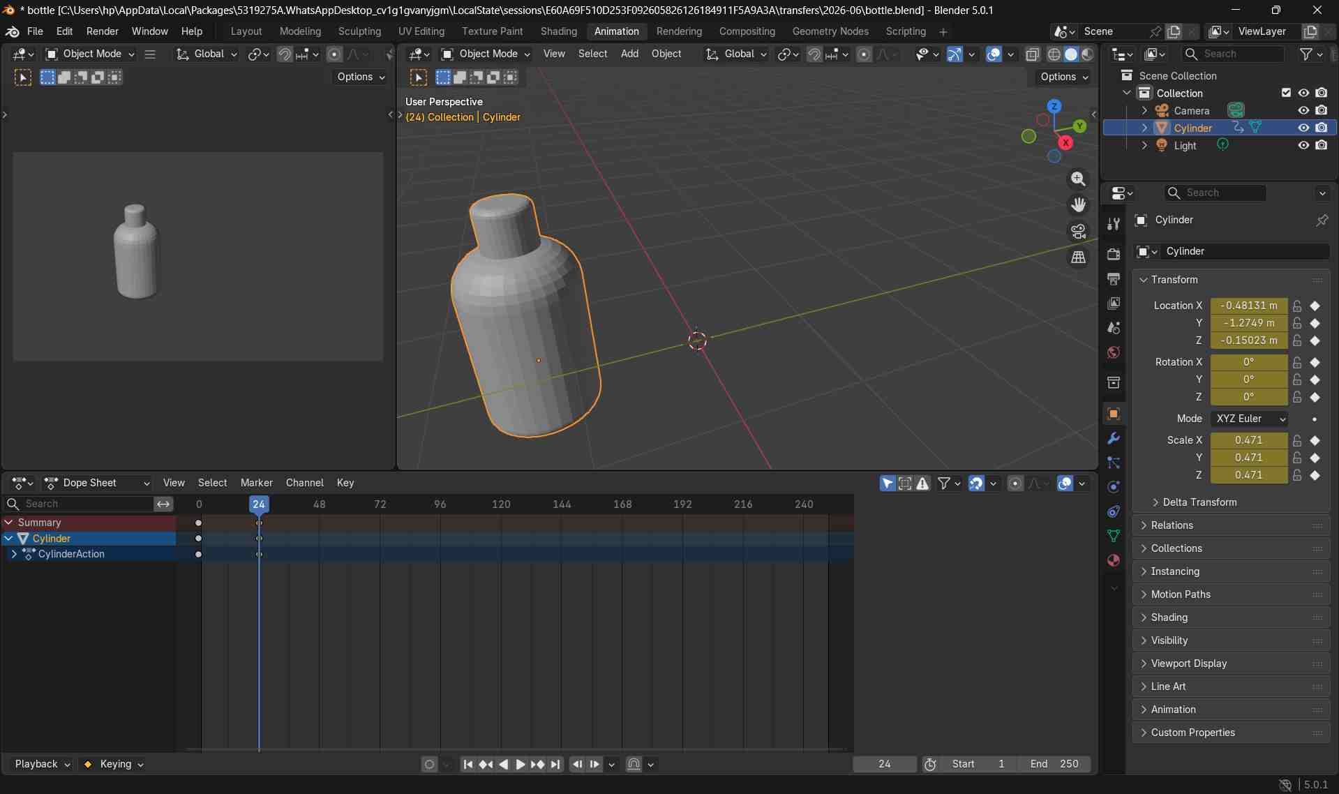
Blender automatically interpolates the movement between the two keyframes, creating a smooth animation.
To add rotation to the animation, I kept the bottle selected and moved the timeline playhead to the desired frame.
I pressed r to rotate the bottle using the mouse. For a controlled rotation around the vertical axis, I pressed r followed by z and adjusted the angle.
Once the desired rotation was achieved, I pressed i to store the rotation value as a keyframe.
When the animation is played, the bottle now moves and rotates smoothly between the keyframes.
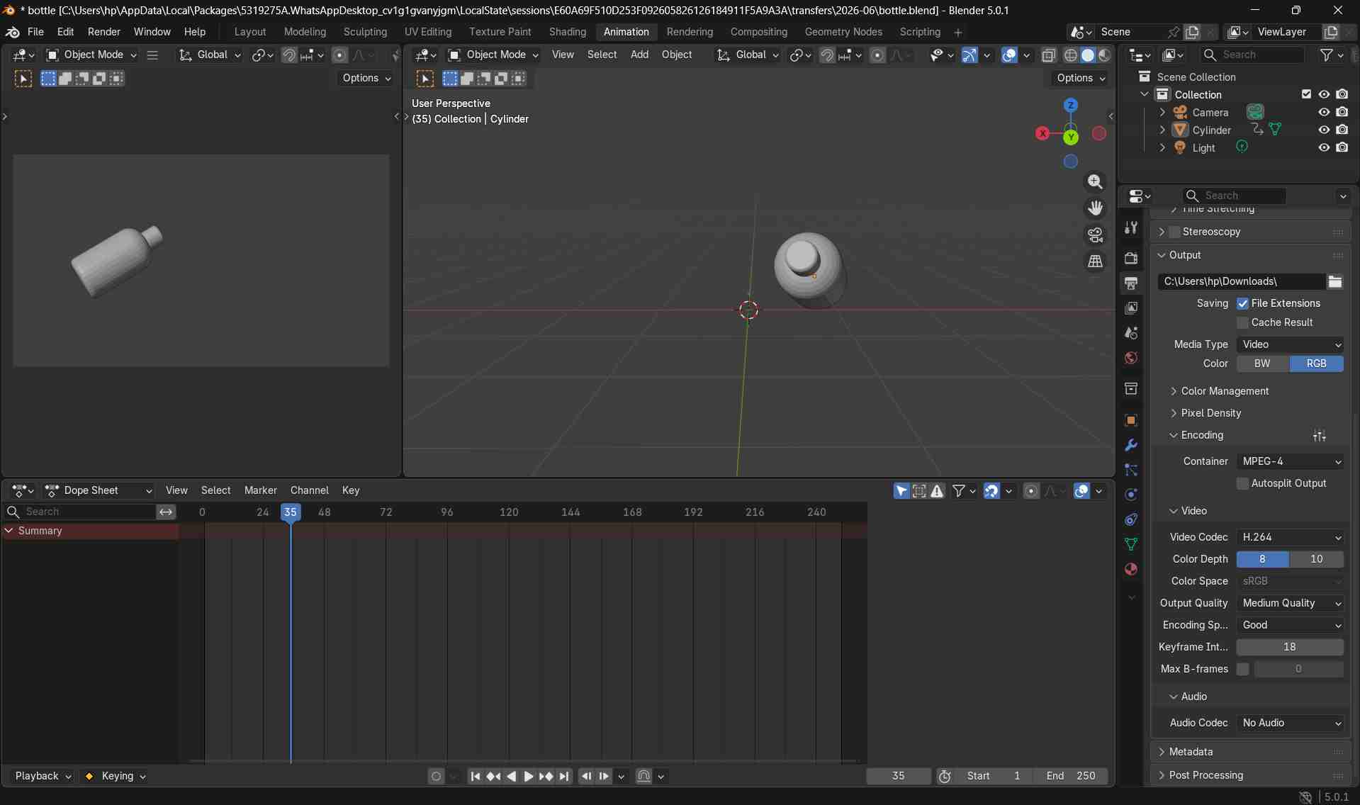
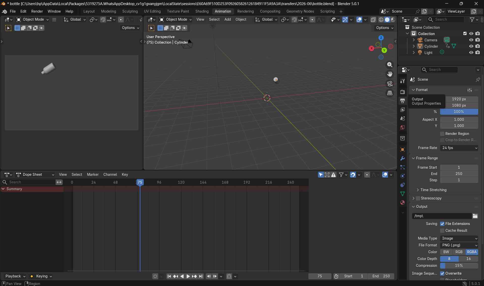
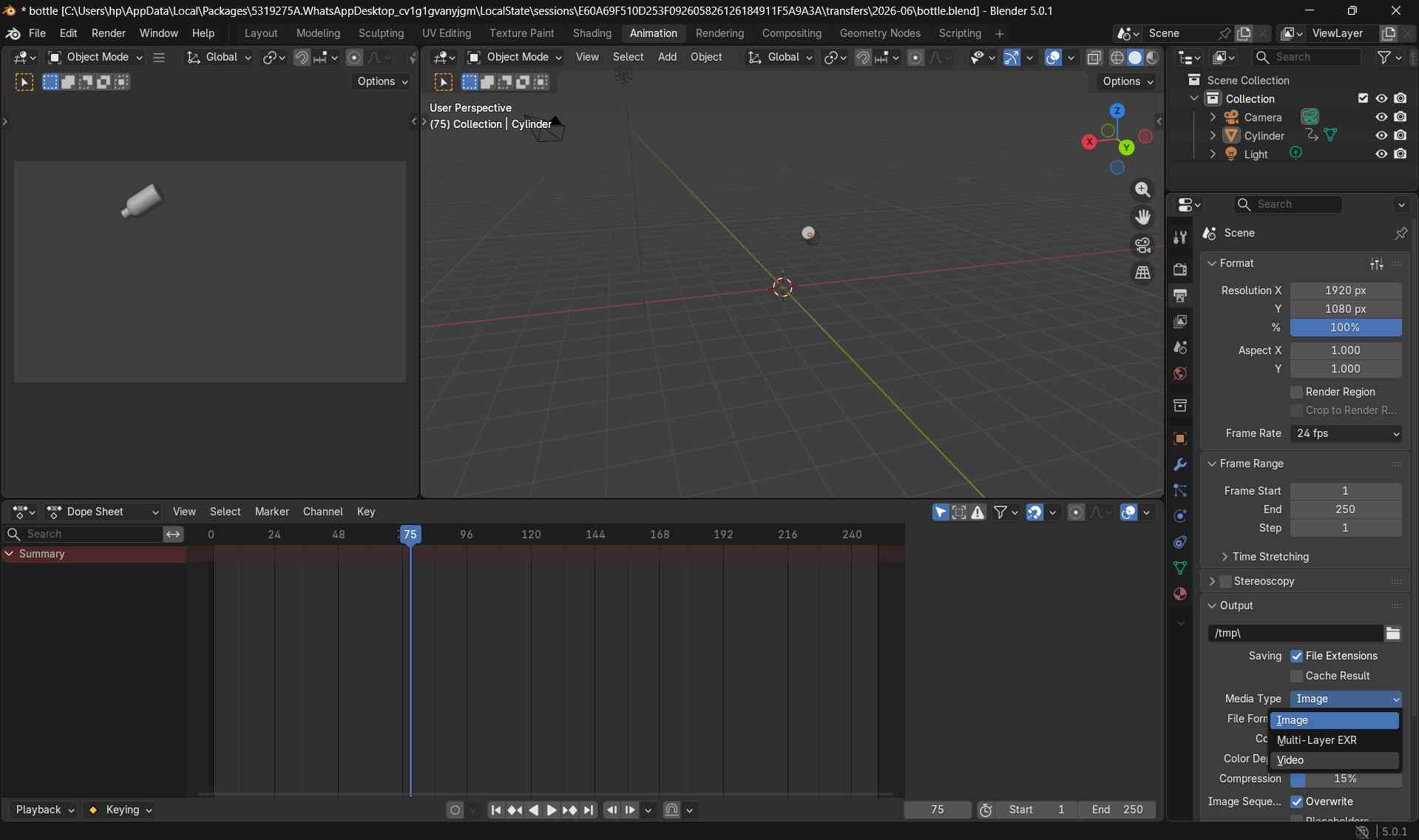
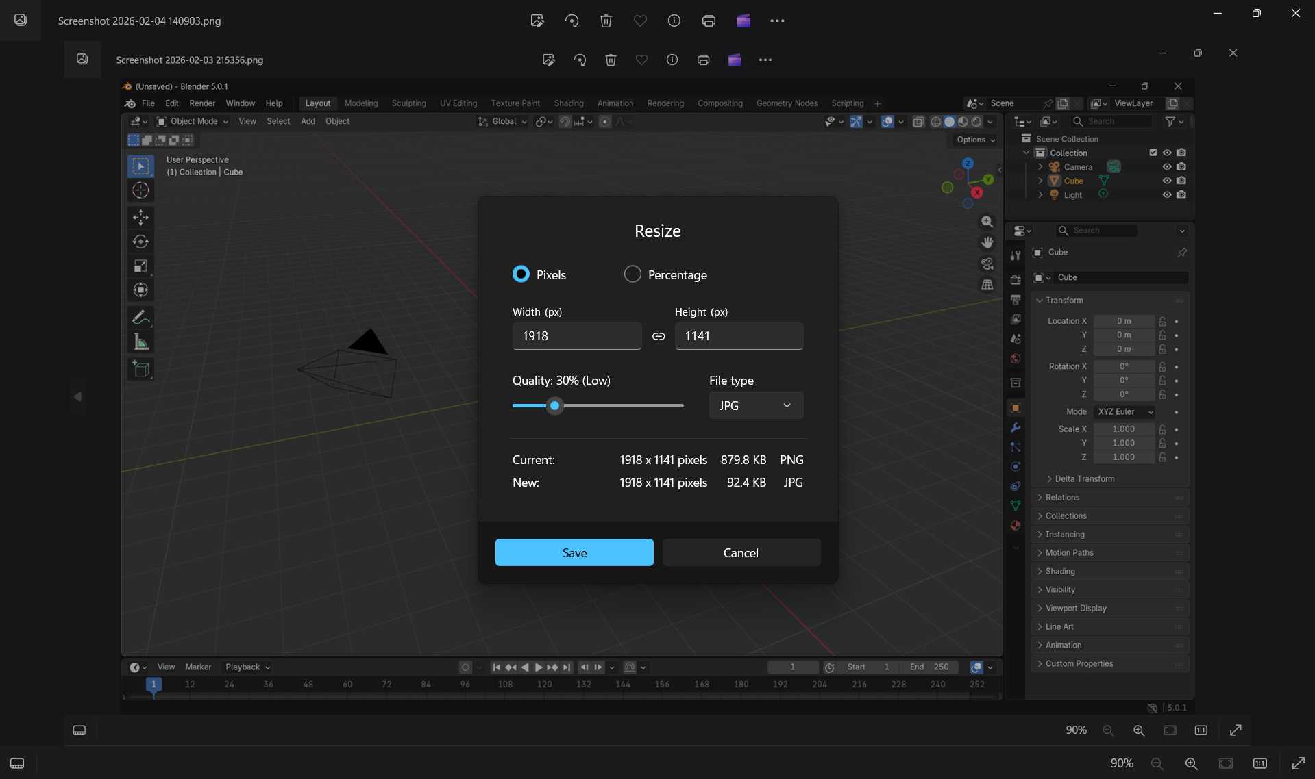
Rendering the Animation
After completing the animation, I opened the Output Properties panel (printer icon) and changed the media type in output format from Image to Video.
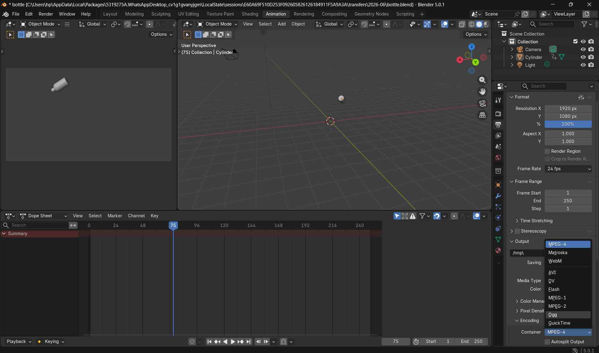
I selected MPEG-4 as the container format and set the video codec to H.264, which produces a widely compatible video file.
I also selected an output folder where the rendered video would be saved.
To ensure smooth playback, I checked the frame rate under Output Properties → Frame Rate and set it to match the animation (for example, 24 or 30 frames per second).
Before rendering, I confirmed that the correct frame range was set so the entire animation would be included.
Finally, I rendered the animation by selecting Render → Render Animation.
Tinkercad
Tinkercad is a free, web-based tool suite from Autodesk used for 3D design, electronics simulation, and block-based coding. It is widely used in STEM education due to its intuitive, drag-and-drop interface that makes complex concepts accessible to beginners and students
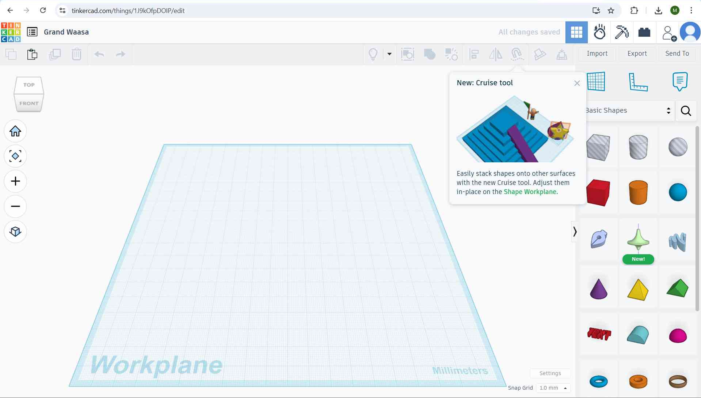
Creating a New Design
I opened Tinkercad and clicked the Create button to start a new 3D design.
This opened a blank workplane where all 3D components were created and assembled.
From the Shapes panel on the right side of the interface, I selected a Cylinder and dragged it onto the workplane.
This cylinder served as the main base form for the pill-shaped dispenser.
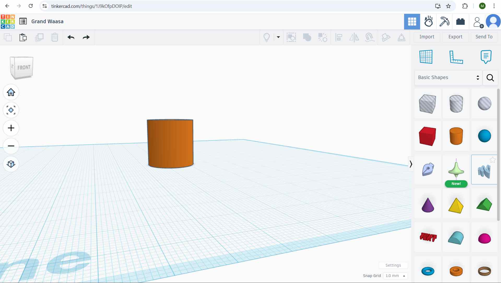
Positioning the Object on the Workplane
I selected the cylinder and used the black height handle to lower it until it rested flat on the workplane.
This ensured the model was properly aligned with the base surface.
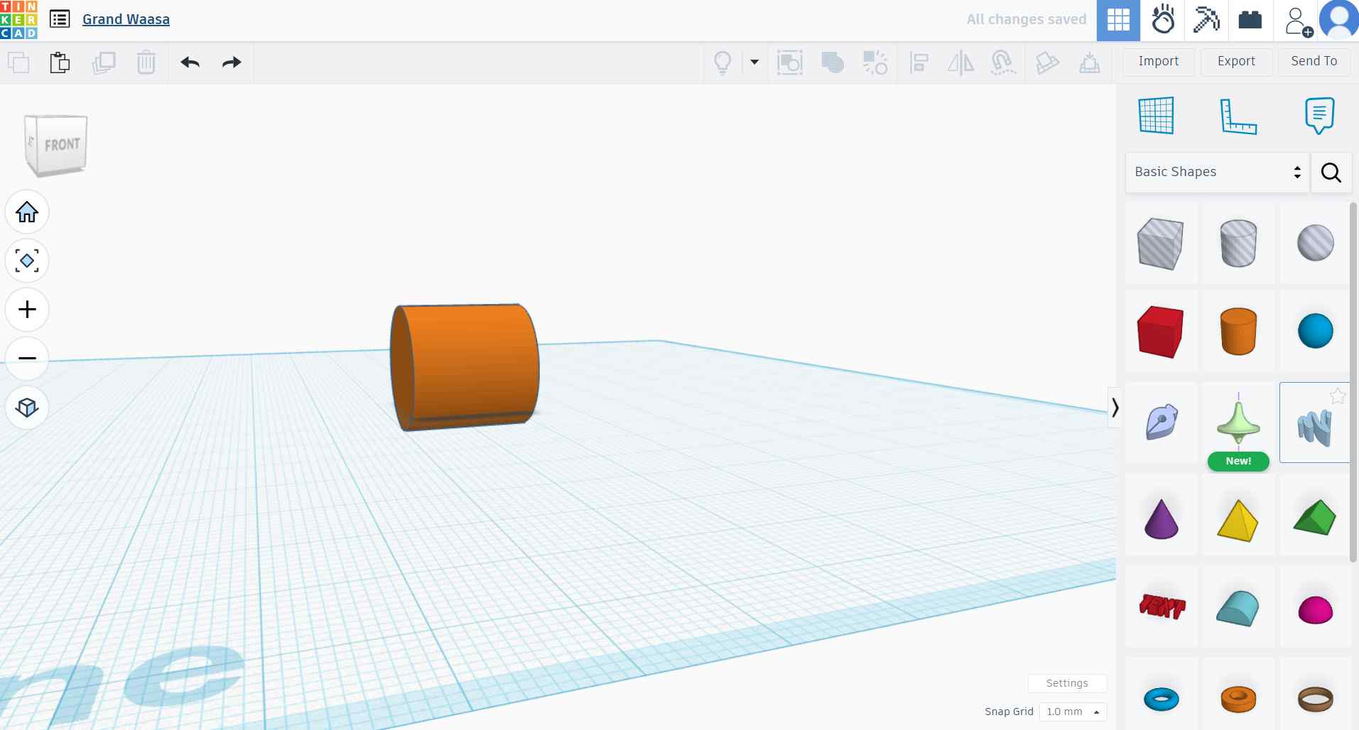
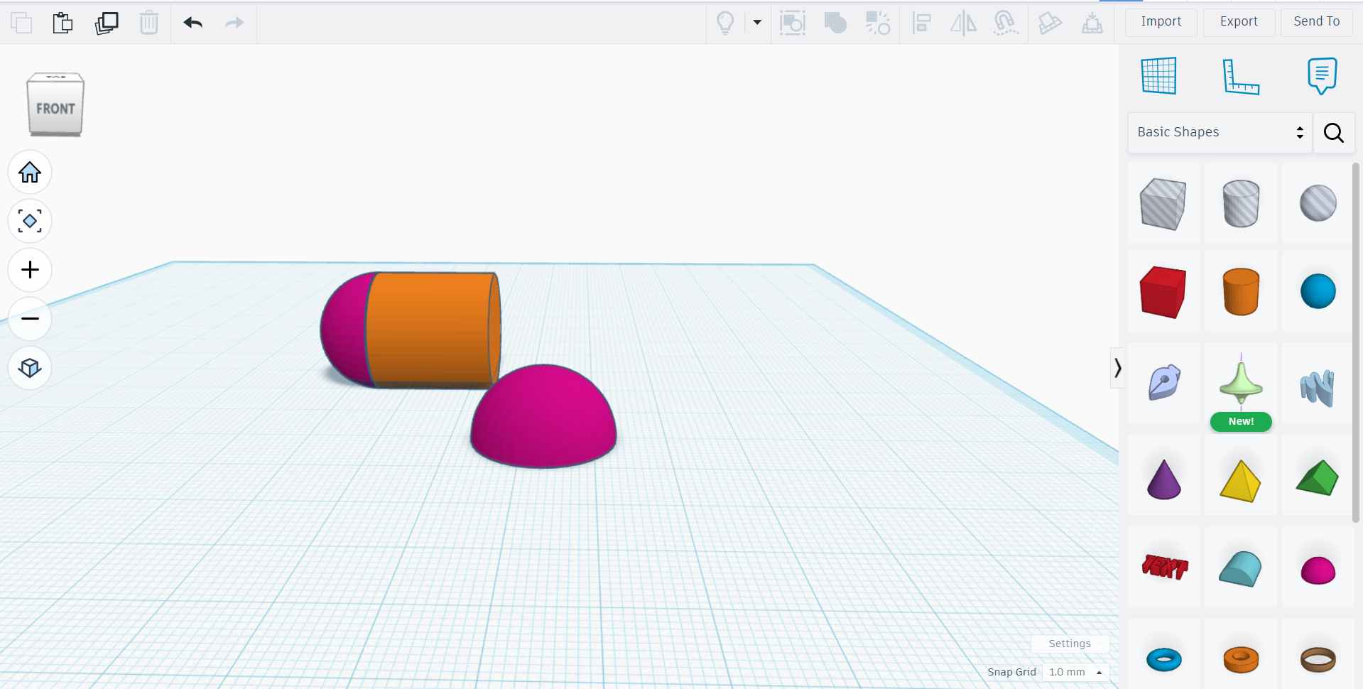
Creating the Pill Shape
To form a pill-like body, I added semicircular ends to the main cylinder.
Since Tinkercad does not support precise point-to-point movement or node editing, alignment was done visually using the ruler tool and alignment guides.
Adjusting the View
To better position and align the object, I rotated the view using the View Cube located in the top-left corner of the workspace.
Rotating the view helped visualize the model from different angles during construction.
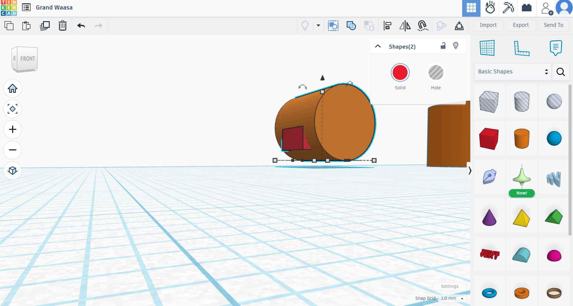
Creating the Screen Frame Using Shape Intersection
To create the frame for the display screen, I placed a rectangular box so that it partially overlapped the main cylindrical body.
I then duplicated the rectangle and converted the duplicate into a Hole.
The hole shape was positioned to intersect with the cylinder at the desired depth.
When the solid cylinder and the hole rectangle were grouped together, the intersecting area was subtracted from the cylinder, forming a recessed rectangular screen frame.
Creating the Medicine Slot Frame Using Intersection
A similar intersection method was used to create the medicine dispensing slot.
A rectangular box was placed near the bottom of the cylinder and aligned horizontally.
The rectangle was converted into a Hole and positioned so it intersected the cylindrical body.
Grouping the hole with the main body removed material from the cylinder, creating a defined slot where medication would be dispensed.
Combining All Components
After creating the base body, rounded ends, screen frame, and medicine slot, all solid components were selected.
I used the Group function to combine all parts into a single cohesive 3D model.
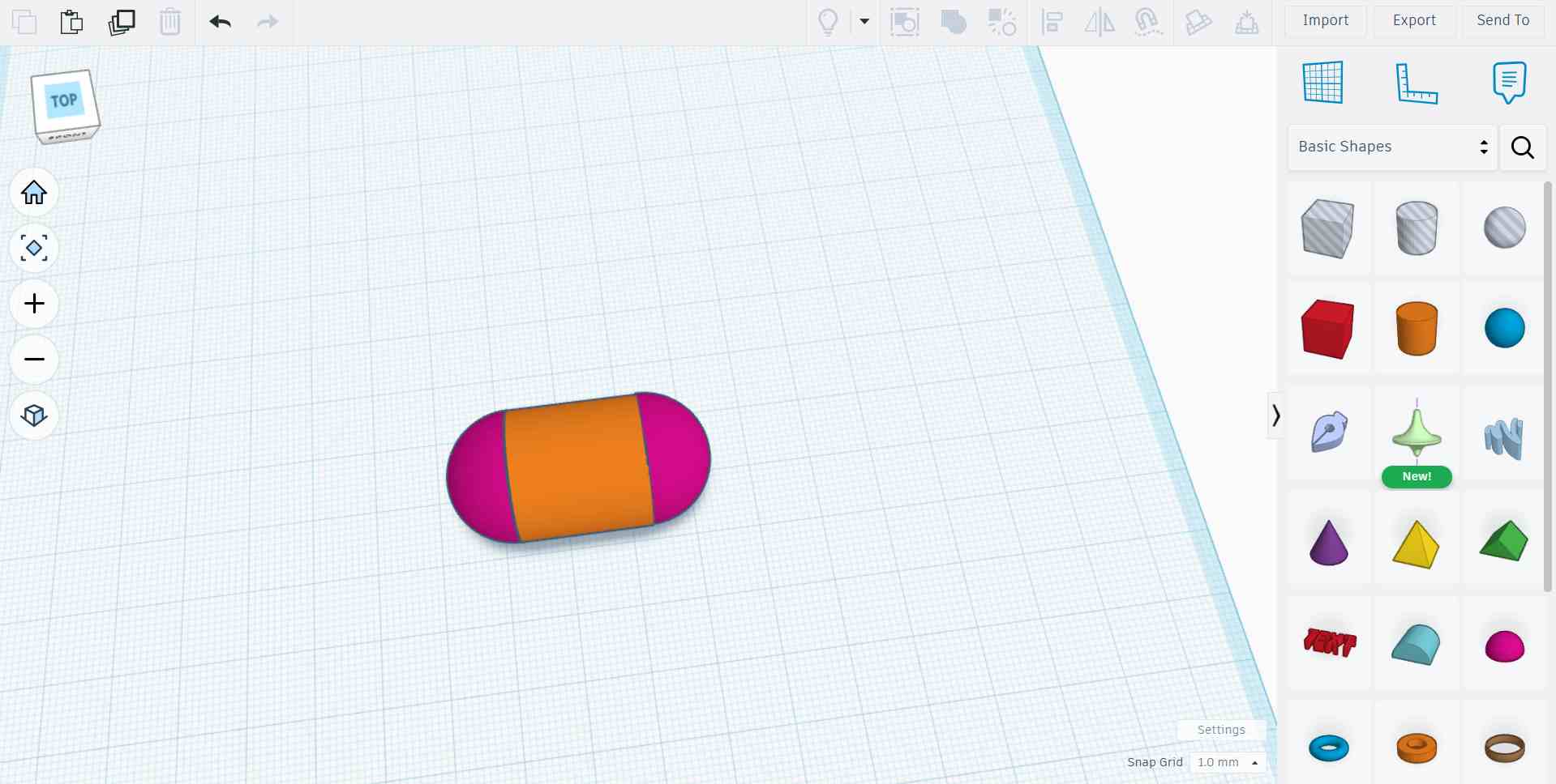
Final 3D Design
The final result is a complete 3D model of a pill-shaped pill dispenser, created by combining basic geometric shapes and using intersection techniques to define functional features.
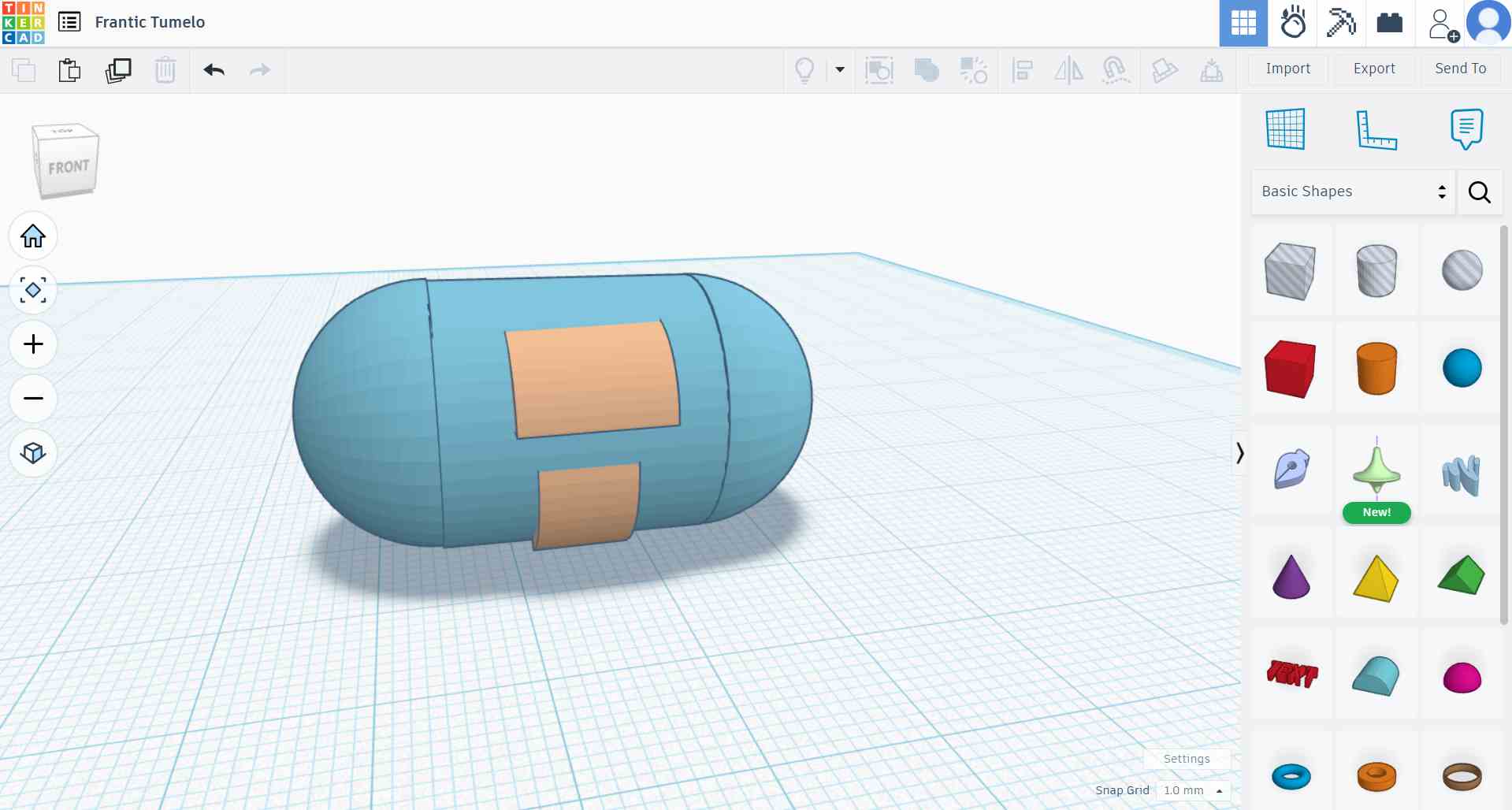
Image and Video Compression
As part of the Week 2 documentation, all images and videos used on this website were compressed to reduce file size while maintaining acceptable visual quality. Media compression improves website loading speed, reduces storage usage, and ensures efficient sharing of design files.
Image Compression
Image compression was carried out using two different methods: the built-in image resizing feature available in Windows and an online image compression tool.
Using Windows Built-in Image Resizing
For basic image size reduction, I used the built-in image resizing feature available in the Windows operating system. This method was chosen because it is quick, accessible, and does not require installing any additional software.
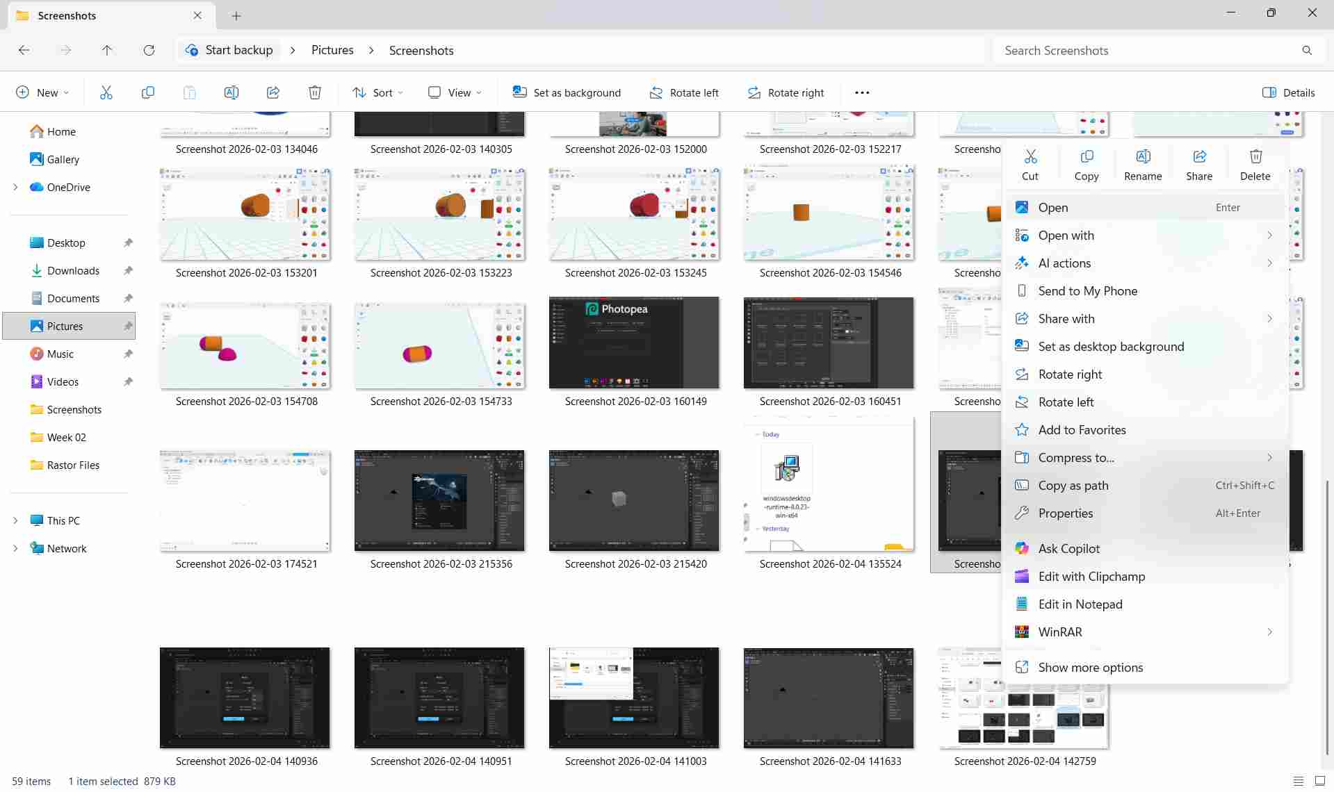
Images were opened using the default Windows Photos application. From the menu options, the resize tool was selected, allowing the image resolution and dimensions to be reduced according to the needs of the website.

This method is quick and effective for simple image optimization without requiring additional software installations.
Using an Online Image Compressor
To further reduce file size while preserving image quality, I used an online image compression website called Image Compressor. You can click on the website name to open the website.
Images were uploaded to the website, which automatically optimized them by reducing unnecessary data and applying efficient compression algorithms.
This approach is useful when handling multiple images or when finer compression control is required.
Video Compression
Video files tend to be significantly larger than images, so compression is essential before uploading them to a website.
Using HandBrake for Video Compression
HandBrake is a free and open-source video transcoder used to compress and optimize video files for web playback.
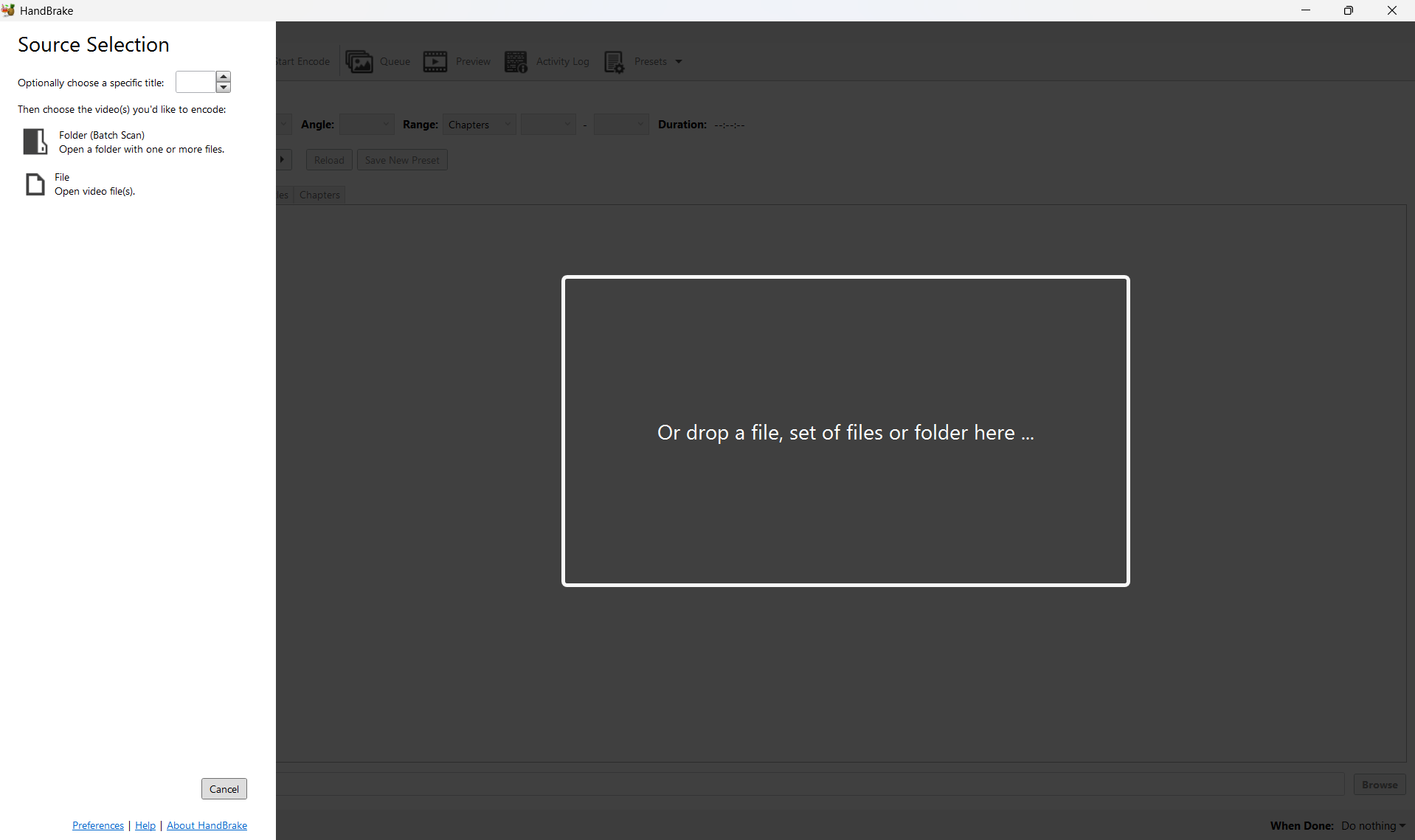
I imported the original video into HandBrake and selected an appropriate preset optimized for web use.
The resolution, frame rate, and bitrate were adjusted to reduce file size while maintaining smooth playback and acceptable visual quality.
After configuring the settings, the video was encoded and exported as a compressed file suitable for embedding on the website.
Importance of Media Compression
Compressing images and videos ensures faster page loading times, improved user experience, and reduced bandwidth usage. This is especially important for documentation-heavy projects such as Fab Academy assignments.
Design Files
The following files were created as part of Week 2 and represent different types of digital modeling and design outputs.
- 3D Model: 3D Files
- Raster Image: Rastor Files
- Vector File: Vector Files