WEEK 17
Wildcard Week
How the week started
This is another week of me wishing to complete the assignment soon as possible. I am planning to make a foldable something in cardboard
How the week ended
Mid way through the weeek I was feeling not good doing something for the sake of the assignment. I had been wanting to make a foot rest for sometime. My legs dont reach the ground when sitting on the chair. Dived deep into pinterest for inspirations, saved pages, etc. I am doing a whale shaped foot-rest. I also cut a wooden frame to test fro my final project
Week 17’s Assignment
- Design and produce something with a digital process (incorporating computer aided design and manufacturing) not covered in another assignment, documenting the requirements that your assignment meets, and including everything necessary to reproduce it. Possibilities include but are not limited to wildcard week examples.
This week I was guided by Amaljith and Revisankar S
Fusion Design- Footrest
This week, I designed a footrest. At first, I wanted to make it in the shape of a fish, but it didn't work. I will add it below. It was designed in the Fusion Sheet Metal workspace, which can create models that can be folded based on the material.
Why this was not tried before: until this week, creasing was not something the other machines could do. A laser cutter could engrave, but it could not create a crease. The Zünd G3 Digital CNC Cutter is the machine that has a creasing wheel and can also cut using a knife. This made it possible to create foldable cardboard models with proper crease lines.
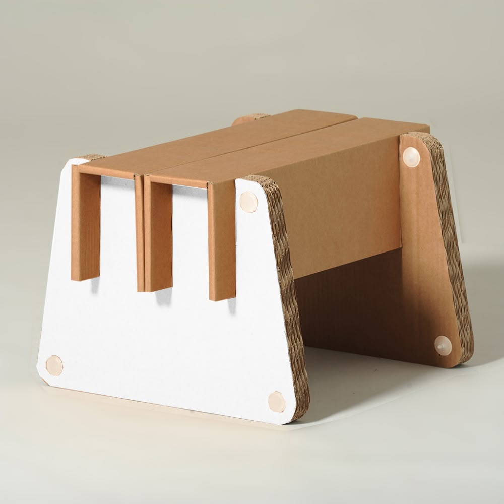
I tried to make this with some modifications.
Fusion : Sheet Metal Modeling
Sketch
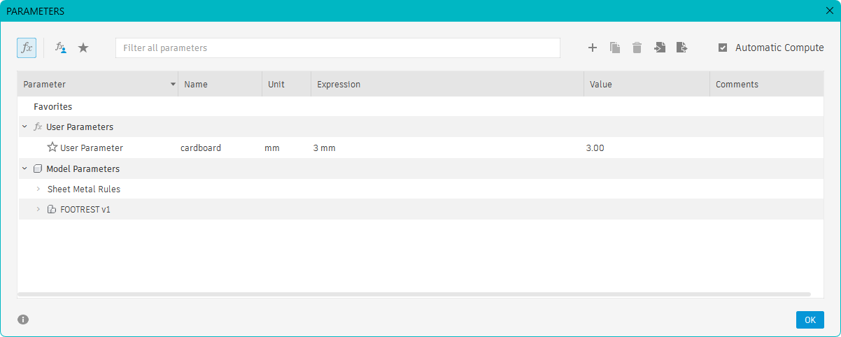
From previous experience, I learned that creating as much of the 2D geometry as possible in a single sketch makes the modeling process easier and more organized.
.jpg)
.jpg)
.jpg)
.jpg)
Sheet Metal and Assembly
After creating the sketch, the model was converted into sheet metal components and assembled using flanges and slots.
.jpg)
.jpg)
.jpg)
.jpg)
.jpg)
.jpg)
.jpg)
.jpg)
Export as dxf file. No need for Color correction like Inkscape.
Clip on how the edge flange was created
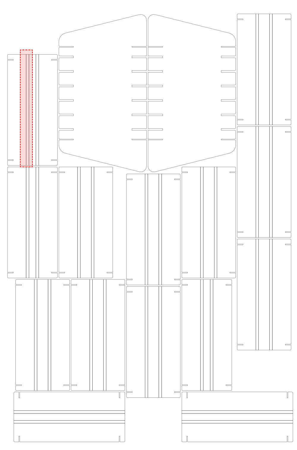
This is how the final DXF file should look. The two highlighted lines are the crease lines required to fold the 3 mm cardboard. The bend position in the Fusion file was set to Outside.
Bend Position: Outside – This determines where the fold occurs when the edge flange is created. Since the bend position is set to Outside, the bend starts from the selected edge, and the new vertical flange wall is created outside that edge.
Now where are we cutting and creasing it?
Zünd G3 Digital CNC Cutter
It's on a ZUND 2D axis flatbed cutting machine. MODEL : G3 Digital CNC Cutter - G3L2500 LINK
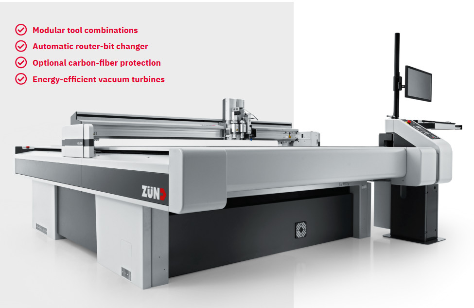
The model here is G3L2500. The L in the name is defined by the bed size of the machine. 2500 is the length of the working area of the bed in mm.
Width (1800 mm / 70 in)
Length (2500 mm, 3200 mm / 98 in, 126 in)
Okay, let's see what exactly this does. The bed here rolls!! Yes, it does. So a roll of material, or an almost infinite length of material, can be fed into it. It cuts the effort of manual removal of material after each cut because of size constraints like a shop board. If the bed rolls, how can it hold the material?
If the bed rolls, how can it hold the material? That's through the action of vacuum suction. Yeah, we are getting advanced this week. At least for me, this is advanced.
So the bed does the holding. The material shouldn't be too porous, or it wouldn't hold the material properly.
So can any thickness be fed into the machine? It's a 2D axis cutting machine, and the movement along the Z axis is limited. The material that can be fed into the machine is limited to 110 mm / 4.3 inches. Even then, if cutting through is to be done, that depends on the flute length. (Often routing materials in the 11 mm to 50 mm range.) And the width of the material is limited to 1800 mm that uis the bed width.
CAM softwares


In Cut Editor, we open the DXF file. It does not matter if the lines in the DXF are red, black, or yellow. Here, we assign the tool by selecting the lines, unlike Job Control CAM.
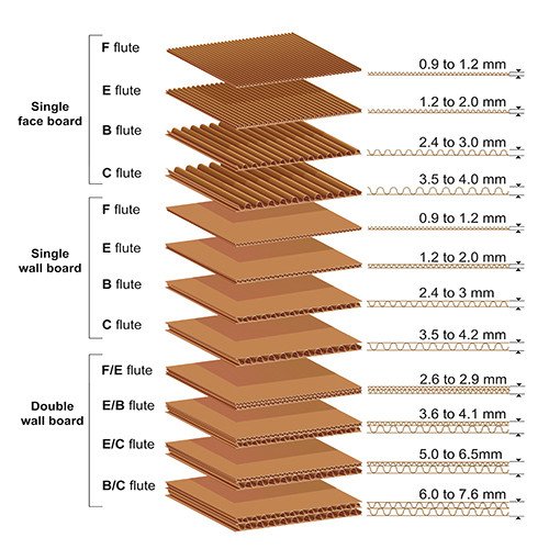
Before we step into the software, something to know about. Cardboard!! There are types of cardboard. Based on thickness and flutes present. Flutes are the ridges seen in cardboard. Along the flutes means the material is weaker than against the flute. Crease depth on along flute and against the flute. Image source
Material : The choosen one is..
A Single wall board B-Flute 3mm cardboard. This was abundant in the inventory. The available Double wall board B-C Flute 7mm cardboard was inadequate in size, though this would have added more strength to the model
ZUND - CAM processor - Cut Editor
Import the DXF file into the ZUND Cut Editor and assign the required cutting and creasing methods.

.jpg)
.jpg)
.jpg)
.jpg)
.jpg)
.jpg)
Important methods used: THRU CUT, CREASE, and REGISTER.
ZUND - Cut Queue
.jpg)
The file send from Cut Editor had appeared in the ACTIVE JOBS section in CUT QUEUE. ( I didnt capture that screenshot so added screen shot of after it was done.) Double clicked on it. It opens into CUT CENTER
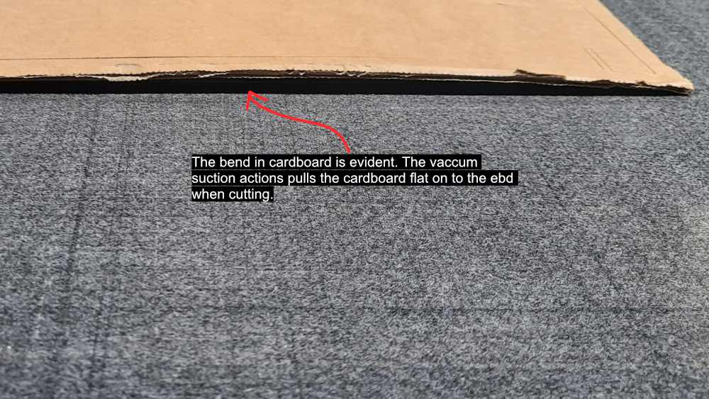
The cardboard has warping issues. since the bed does vaccum scution it pulls the carrdboard flat. If it was lazercuter one has to paste it on the bed with paper tapes , even then it would have caused uneven cuts.
Place the cardboard on the bed. "NOTE THE FLUTE DIRECTION"
Cut Center
.jpg)
.jpg)
.jpg)
.jpg)
.jpg)
.jpg)
Creasing
Shows how the creasing tool creases, and how the tool lifts between creases.
Shows how easily the pieces separated.
Folding
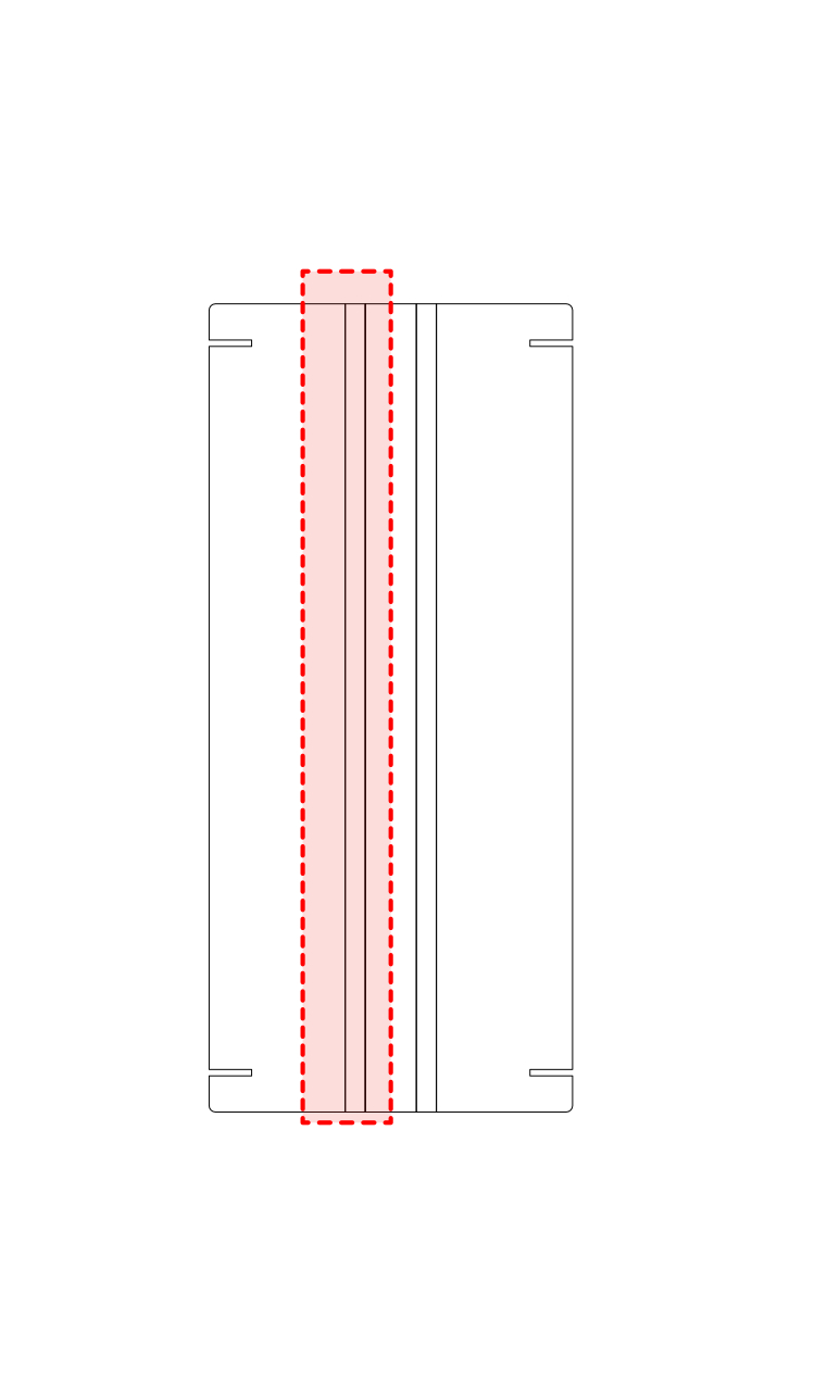
These two lines we see are the crease lines made for creating one fold. Fold the cardboard along the fold lines, and this creates the 90 degree fold we did in the design.
The cardboard has to be bent along the crease line. You can see that in the video. There are two crease lines made, and that is how the cardboard could fold well.
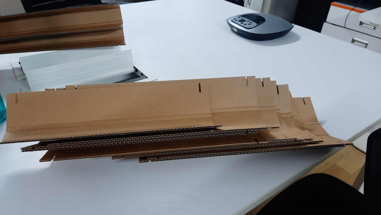
Assembling
I inserted the horizontal pieces on the top and bottom first so it holds the shape, then added the other pieces.
Hero Shot
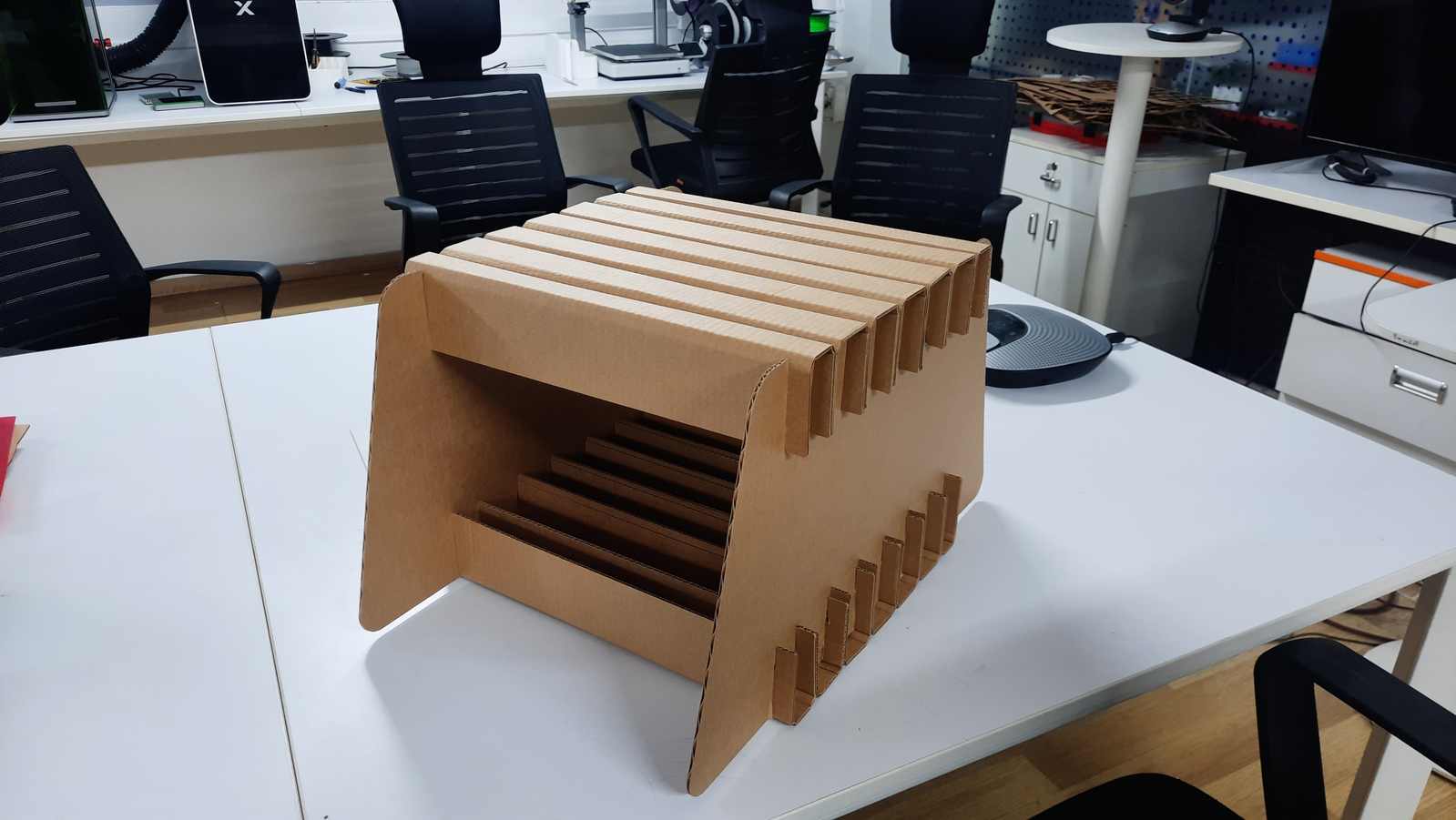
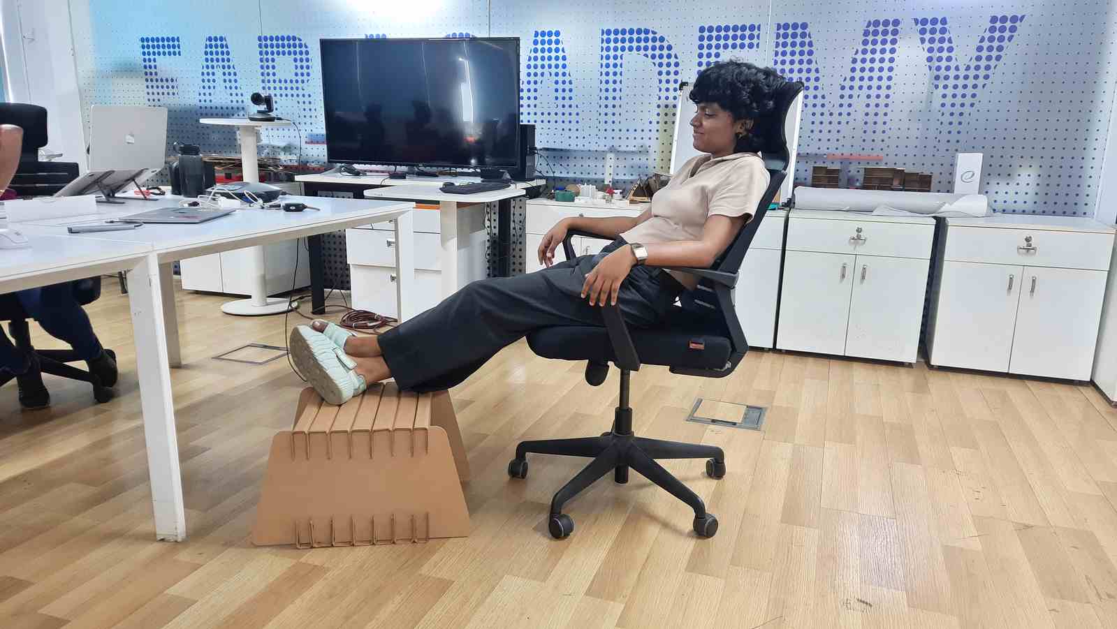
In picture is Ashtami.
What I learnt was that the ergonomics of this model are a bit off. It is higher than a normal footrest, so it may not work for everyone. But it works for me because I keep my chair raised so that my elbows rest comfortably on the table and chair. When I place my feet on the footrest, it feels comfortable and supports my sitting position well.
The model was not supposed to work this well because it is made from 3 mm cardboard, but it is able to hold the load. I think this is because of the horizontal folds that reinforce the structure and make it stiffer. If two additional vertical supports are added on each side, I think it would perform even better and carry more load.
Prototype Exploration: Whale Footrest
At first I wanted to design the footrest like a fish, a whale, with two different heights where the feet could be placed.
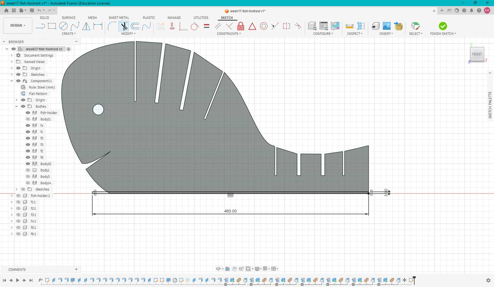
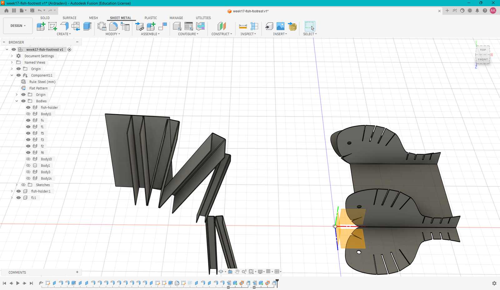
I designed it in Fusion, but had a hard time creating the flanges. The angles were not 90 degrees like the footrest design I had made earlier, which made the modelling process more difficult.
I was finding it hard to create that, but somehow managed to do so. I was told that I had to create interlocking slots, because only then would the model be able to resist shear forces properly. This was way too complex for me at that stage.
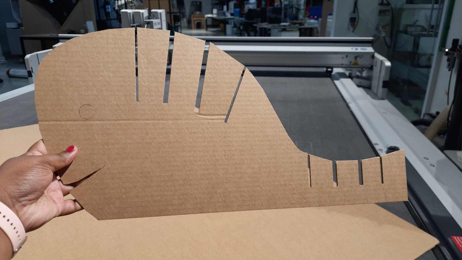

As suggested by the instructor, I decided to do a test cut and see if it would work. I followed the same creasing steps, but only one fold was created because of the geometry of the design.
The cardboard was not folding properly into the angled shape, and the vertical slots were also not strong enough to support the structure. They bent under the load, causing the model to lose its shape.
The main iput i took was the flue direction. The flutes must also be along the vertical direction of the vertical support.
I dropped this model and decided to create a simople footrest instead. At the end of the week, I had a working footrest, so I am happy with the outcome. I have been using it ever since.
Refrences I took
Sheet Metal for Cardboard? Here’s Why It Works (Fusion 360)
Fusion 360. Unfold sheet metal components into flat patterns
Thomas Noah- Wildcard Week
Basil Abraham -Wildcard Week