Week 16: Wildcard Week - Zund Machine
Individual Assignment: Design and produce something with a digital process (incorporating computer-aided design and manufacturing) not covered in another assignment, documenting the requirements that your assignment meets, and including everything necessary to reproduce it.
Introduction to the Zund machine
I have chosen to focus on learning the basics of using the Zund machine which is here in the Kerala lab which is a model G3-L2500 (L=large and length is 2500 mm). Details from manufacturer here.
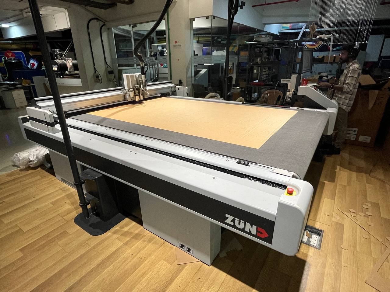
Zund machines are highly-sophisticated multi-axis Swiss machines which can cut a large variety of materials from cardboard to textiles to plastics. The Zund machines are a great option for many materials which cannot be cut with a laser cutter. Here is the availability machine in it's glory:
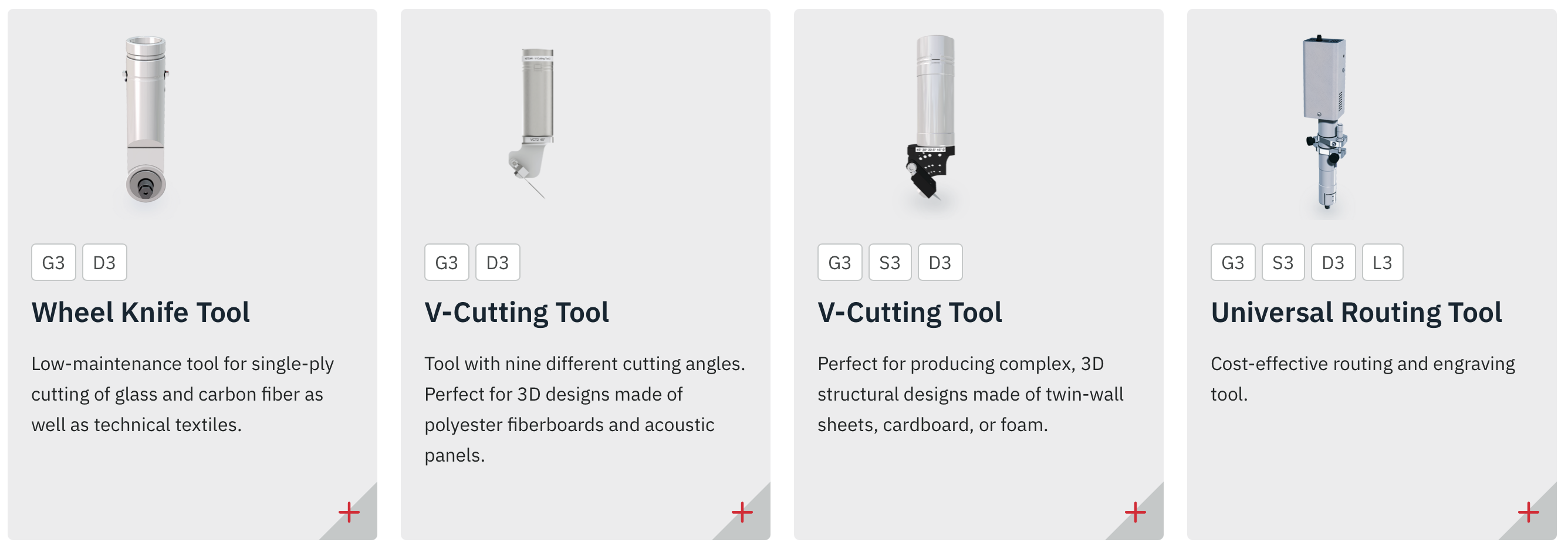
The machine has a few heads within which different tools like knives, creasing wheels, routers, and other modules may be inserted.
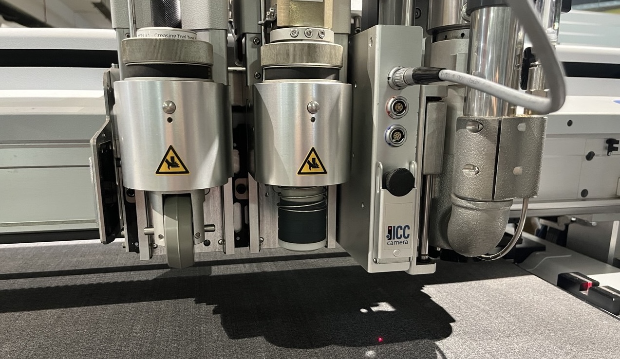
There are a total of 27 such modules and tools available from the manufacturer.
My Project Idea
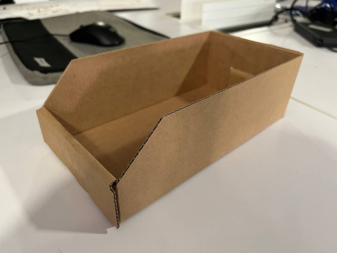
A small but realistic useful project I'm interested to pursue this week is a set of cardboard drawers for small equipment pieces modeled after one here in the lab.
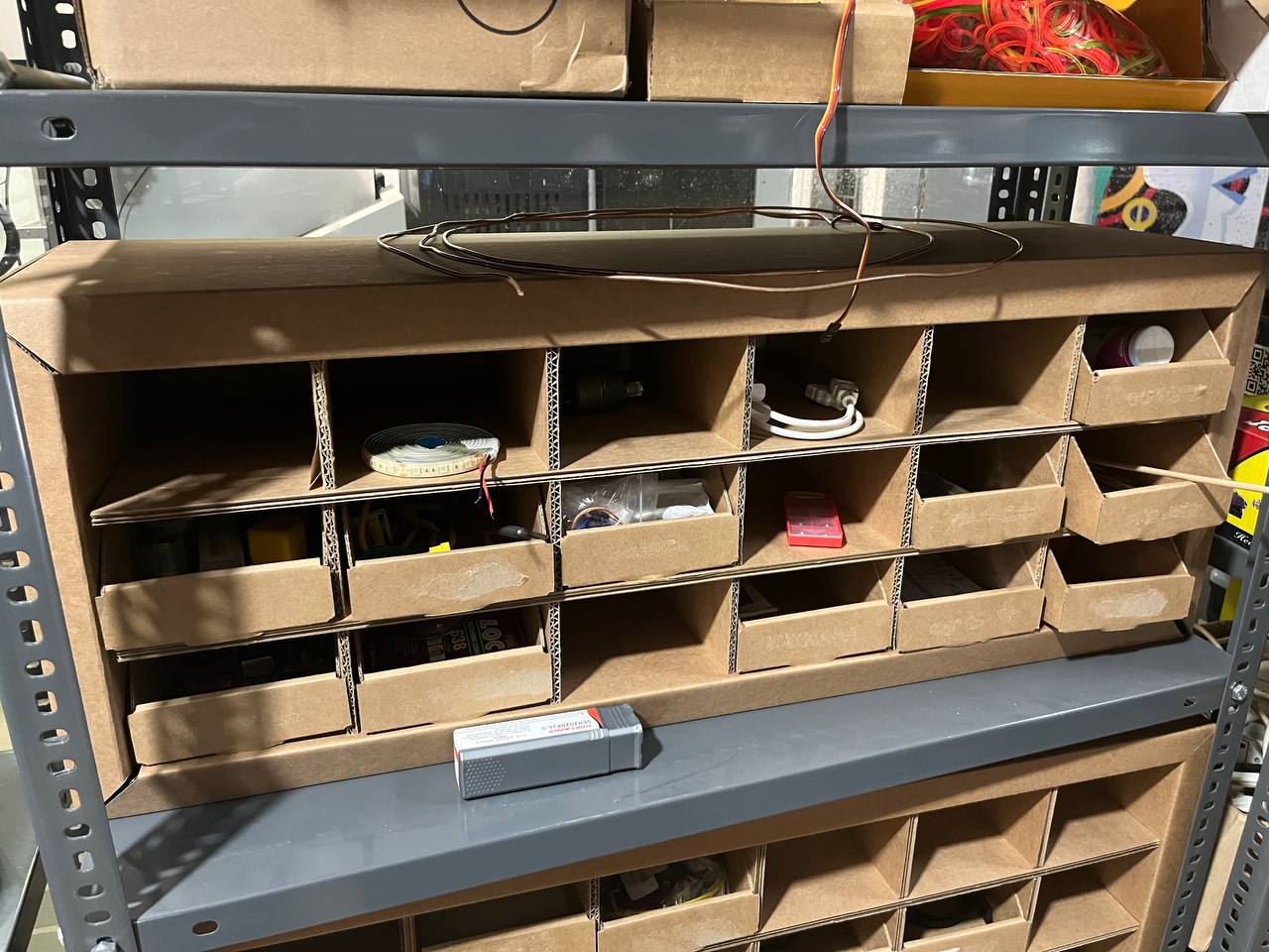
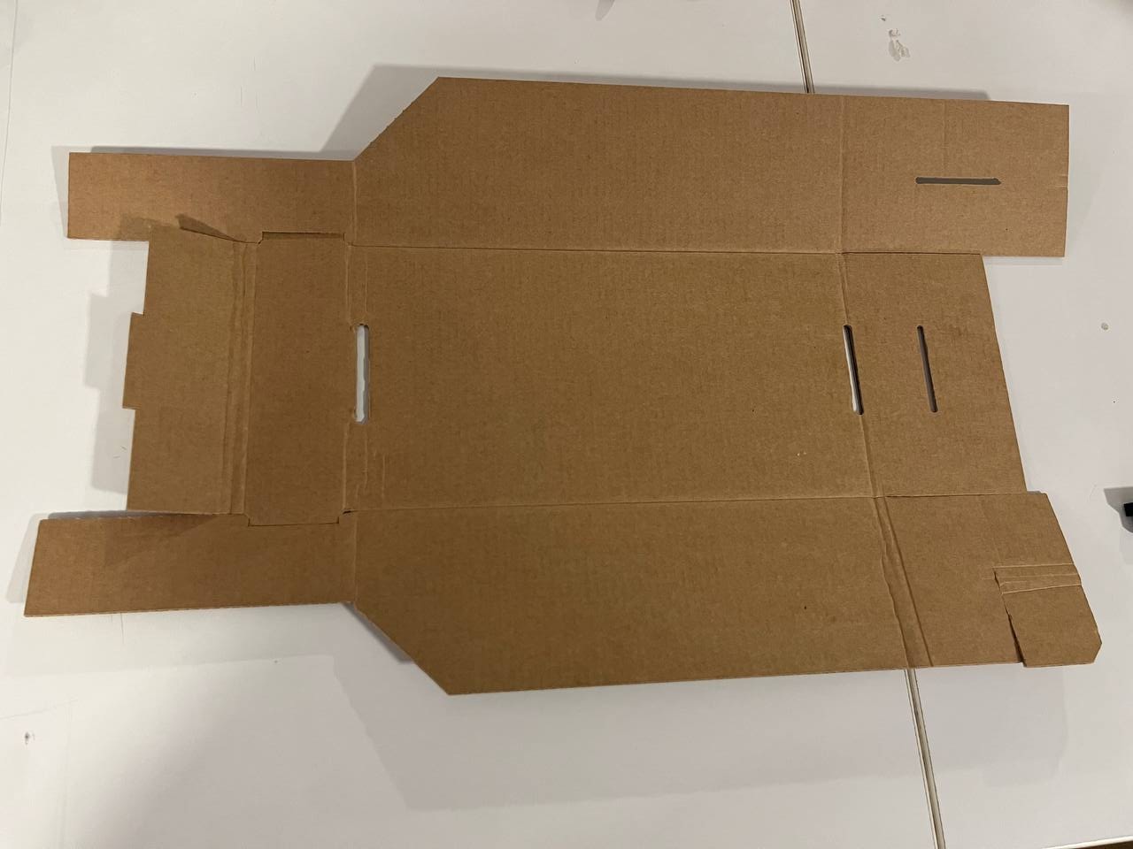
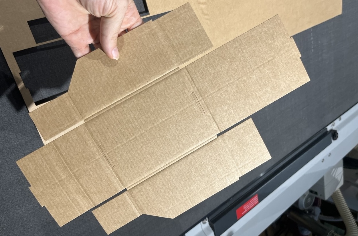
Here is the individual drawer which I'll need to model, first assembled and then spread out:
Will also need the entire larger case structure eventually, but that is beyond the scope of this week's assignment.
Designing the Project
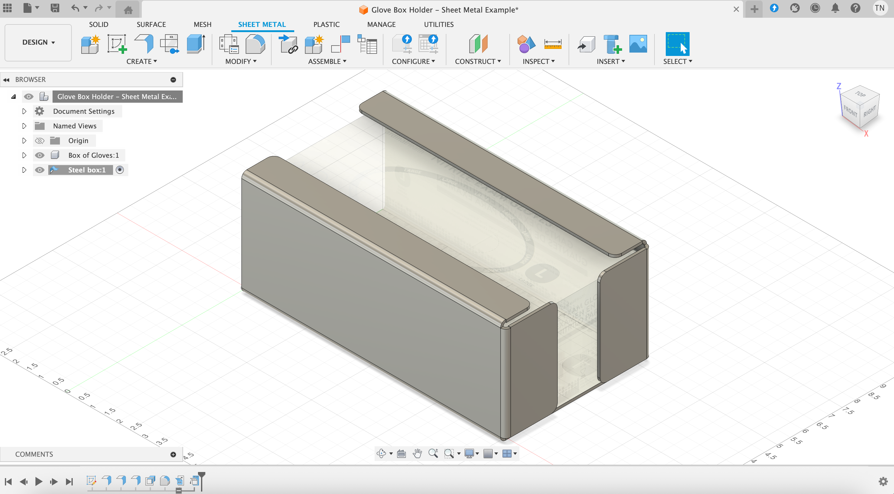
Fusion 360 can be used for preparing files for cutting on the Zund machine. In particular there is a "sheet metal" menu, which I never tried. I started by watching a tutorial here. Hence, I followed the steps and understood some of the basic functionalities, achieved the desired outcome shown here:
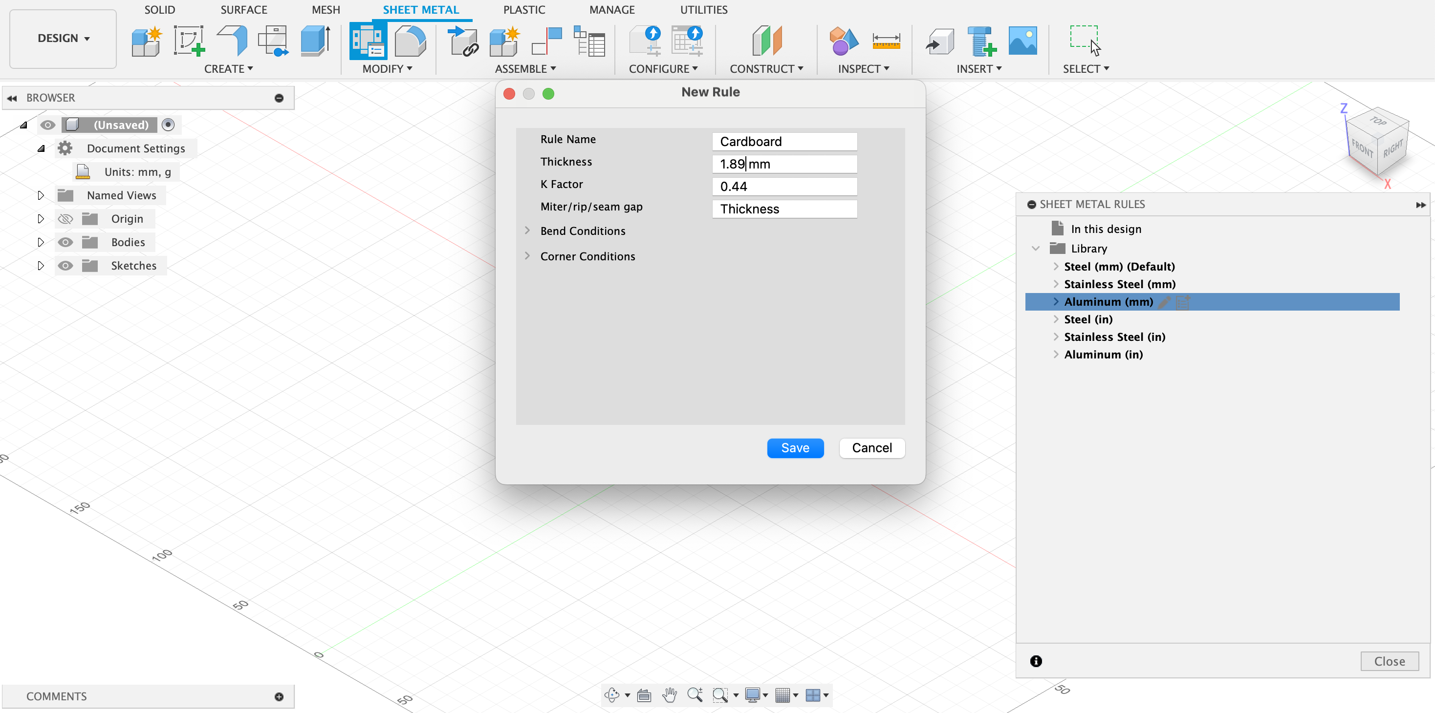
Now I'll begin to make my own design for a box, however we must first set up a new rule for cardboard. As shown in the screenshot below, we navigate to "Sheet Metal" -> "Modify" -> "Sheet metal rules", and from there create a new rule for cardboard. Some values need to be measured, and information entered. These values are parameters specific to our material, and every new project with a different material should to be set up in a similar manner.
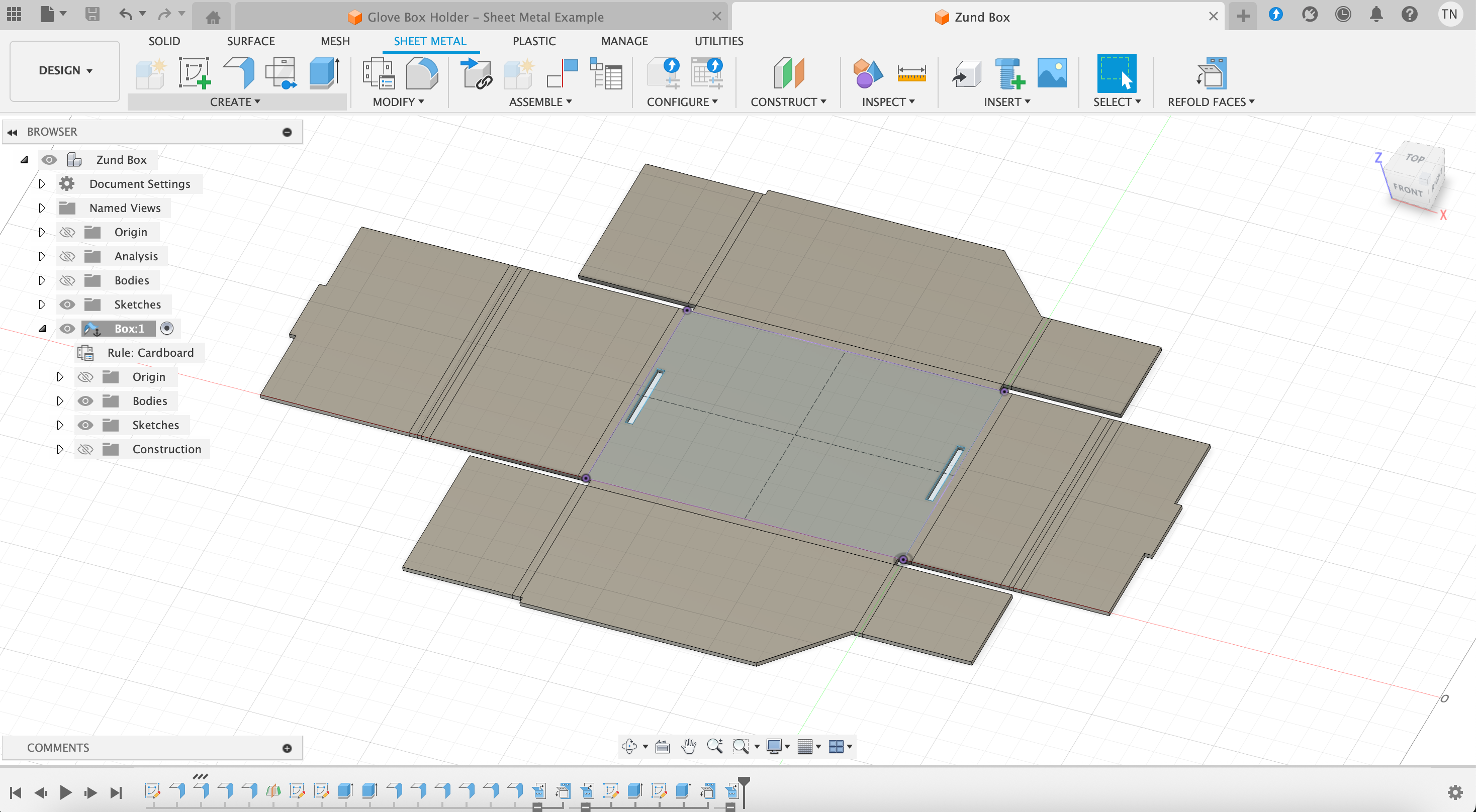
Having learned the basics of modeling a box, in particular about flanges (bent faces), I was able to proceed without such difficulty. Here is the box more than half complete, and already note the number of flanges in the timeline. Again, flanges are simply bent faces, so any time we want to bend cardboard we need to click the option for a new flange!
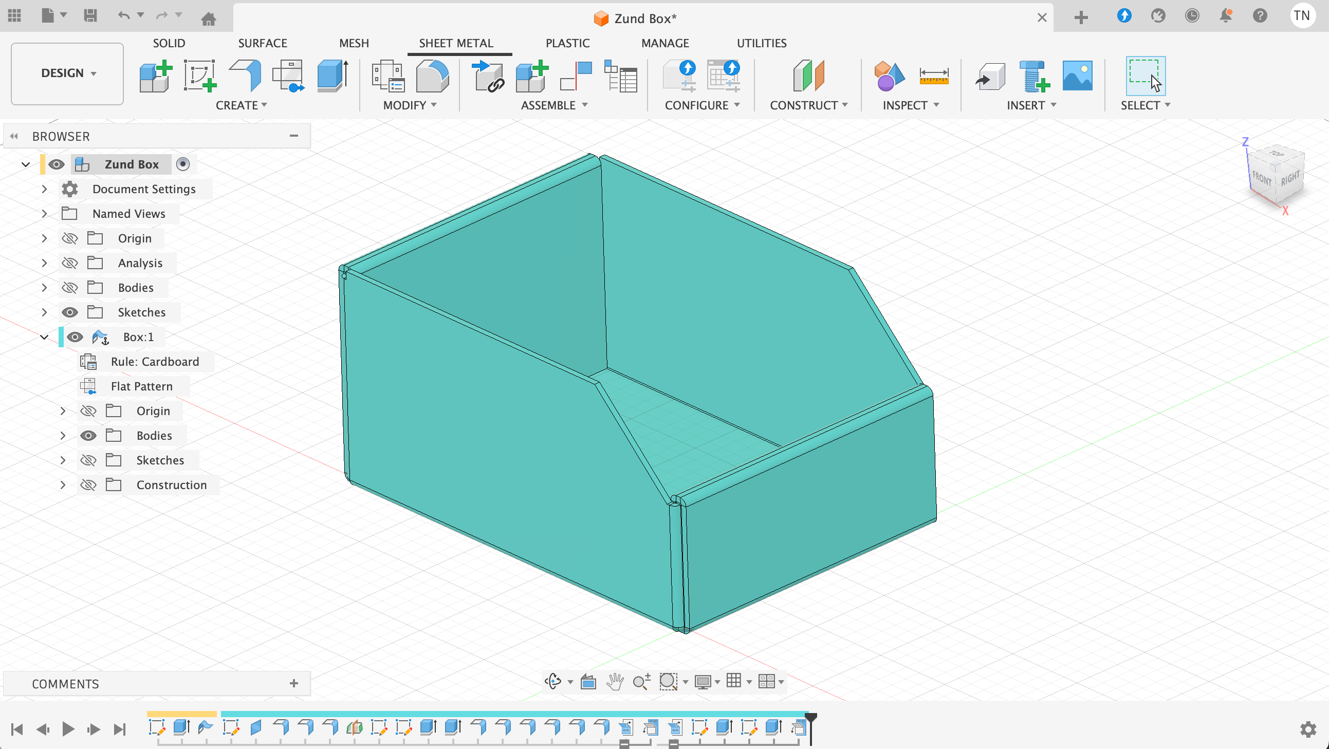
Following this process, we were able to complete the design for a simple box.
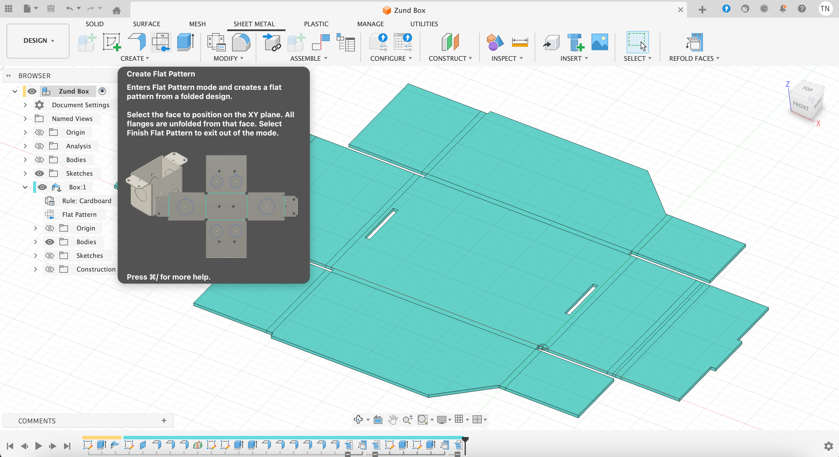
To unfold the box, we navigate to "Modify"->"Unfold". We must subsequently choose the stationary entity (bottom of box) and which bends to unfold (all).
Using ZUND Machine for Production
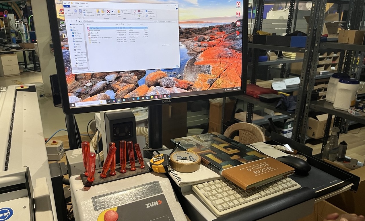
As we have finished the design in Fusion, flattened it, we must now export as .dxf and send that to the computer connected to the Zund machine. Here we see the set-up with our .dxf file (available below) about to be opened...
There are 3 sets of software that are used and in order: Cut Editor, Cut Queue, and Cut Center. We'll go through them all:
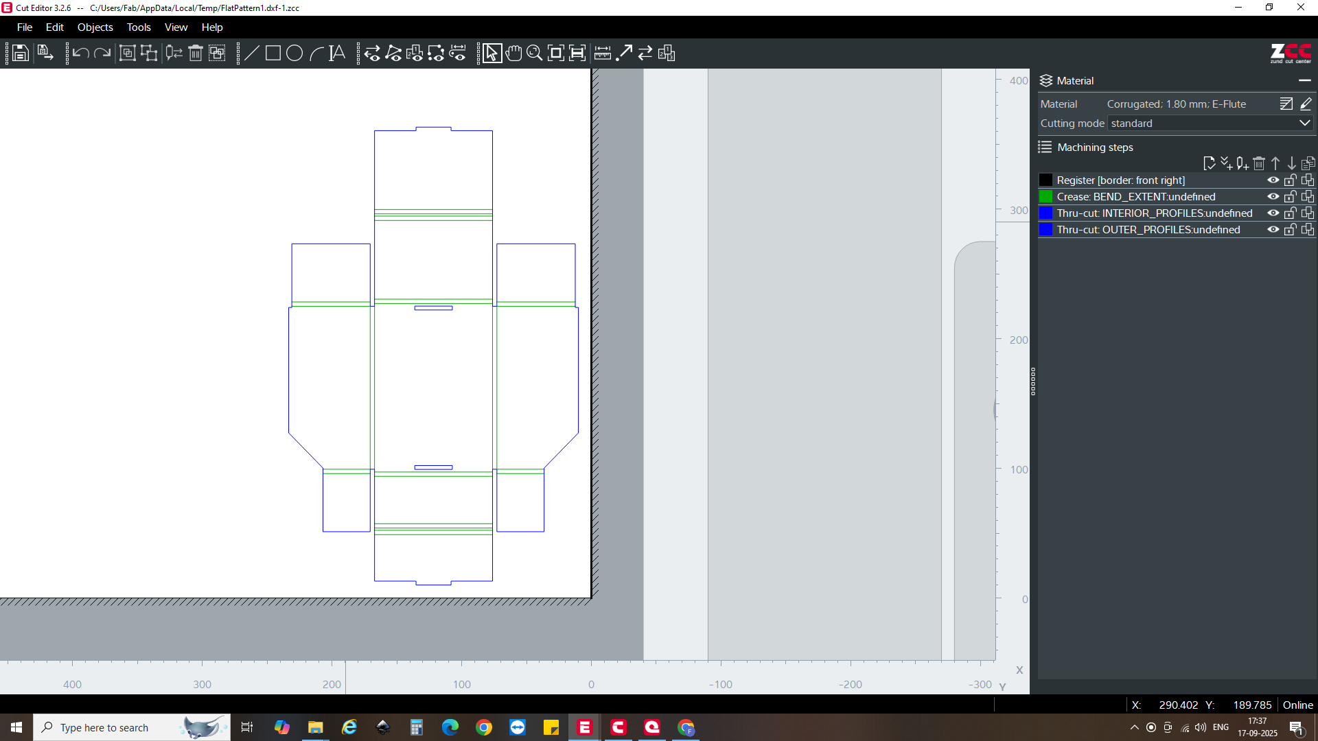
Cut Editor: we import the file into cut editor, and here we specify the very precise material type as well as the operations to perform in the different parts of the design.
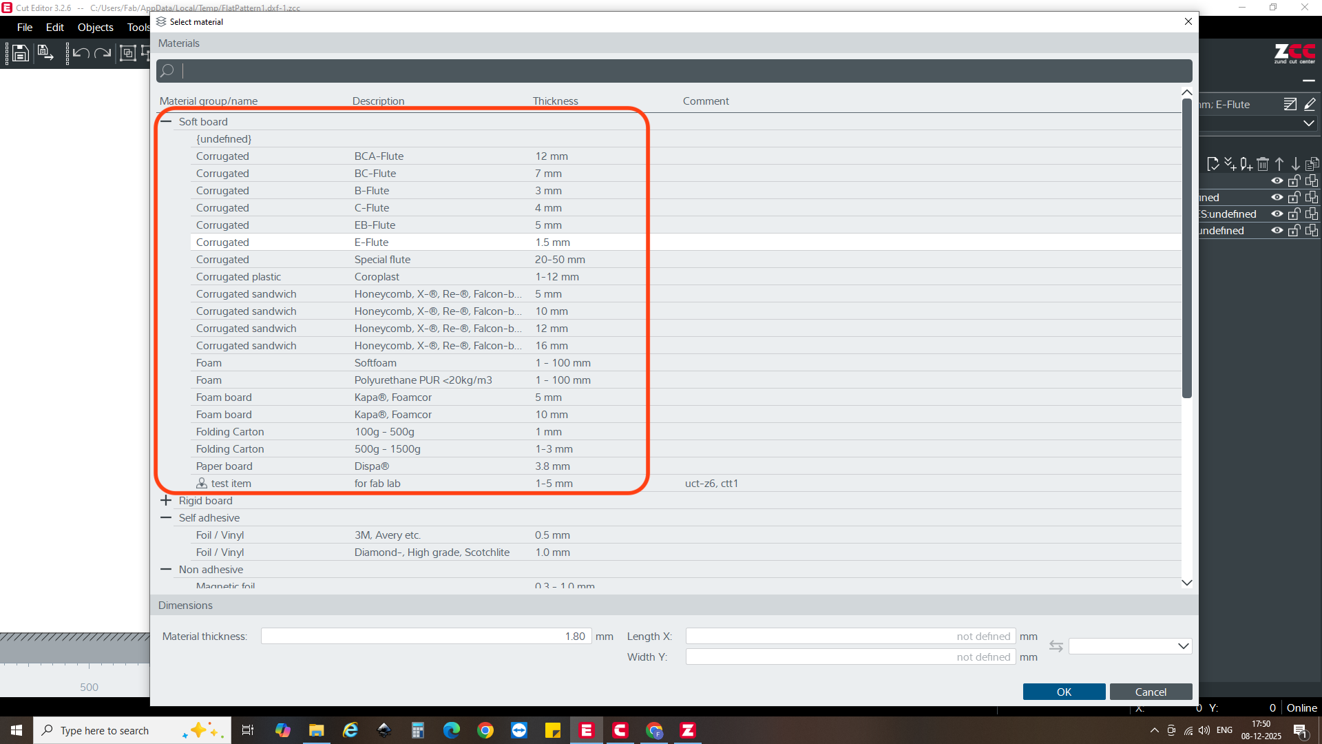
First we should choose from the huge variety of material types, shown below are just different types and thickness of cardboard!
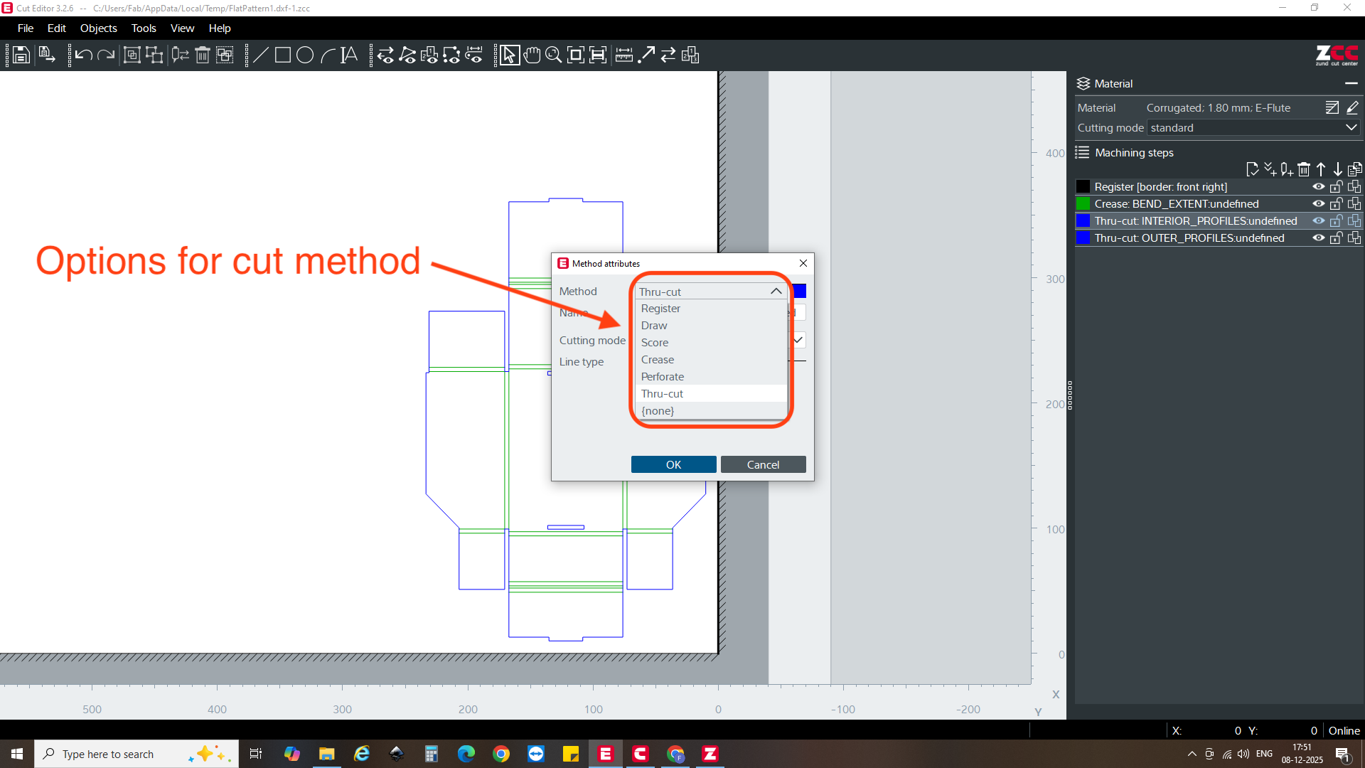
Subsequently we should choose between options like "crease" and "cut", then within those choices there are additional options, for example here we see different types of "cut"
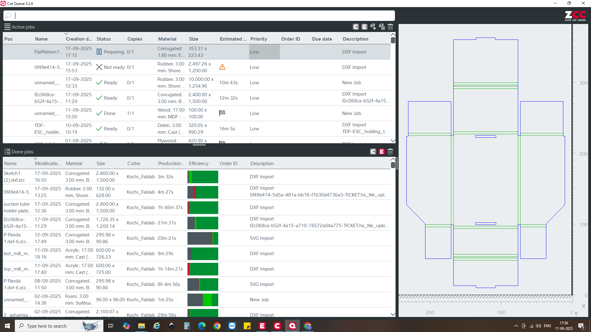
Cut Queue: this software is not so relevant for our context, but in large factories with multiple people pushing jobs it will be helpful to organize the production.
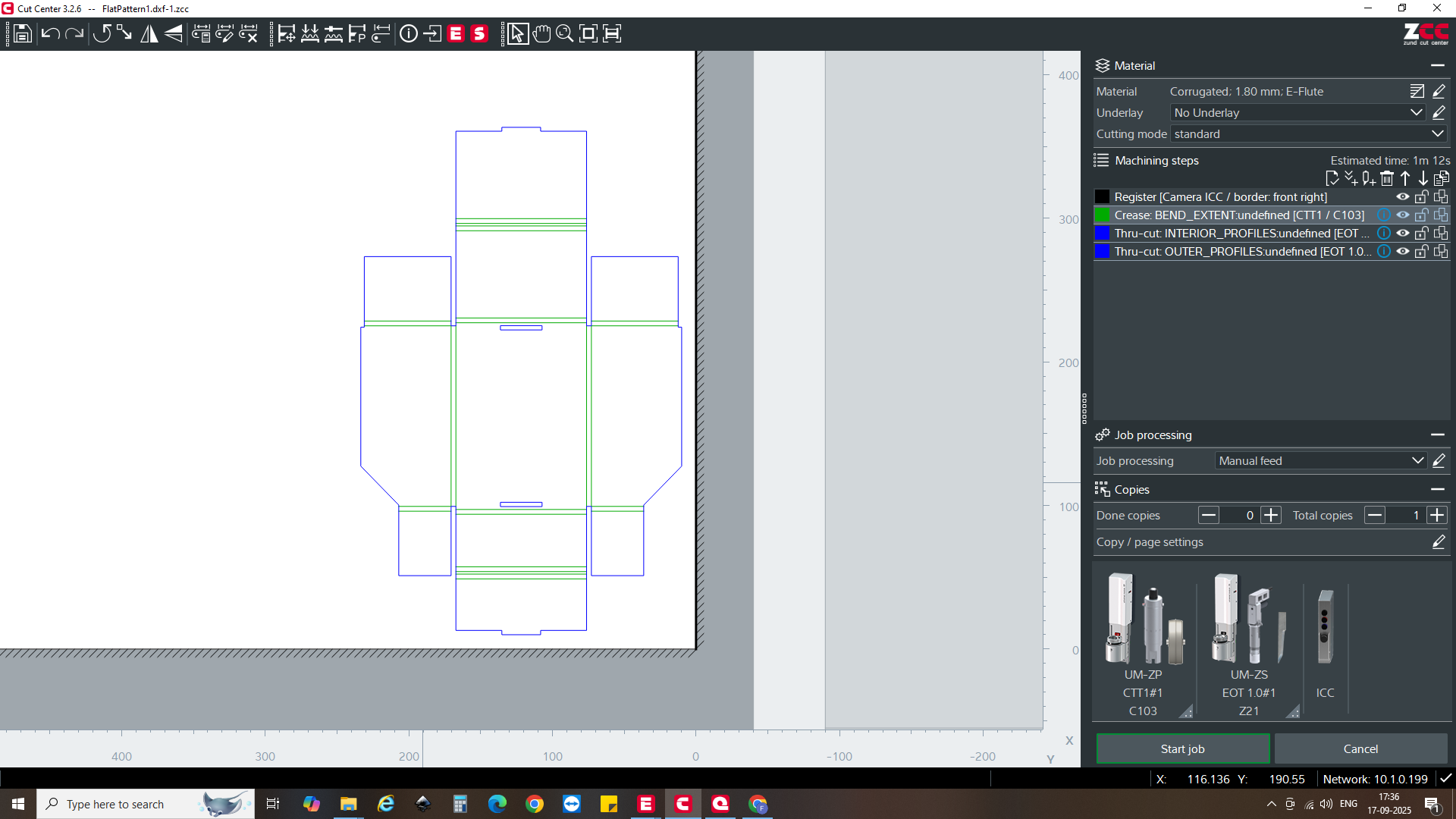
Cut Center: this is where the tools are selected for the particular job. In the below screenshots we see first the tools chosen for each task, and second the parameters for those tools such as speed and cutting depth.
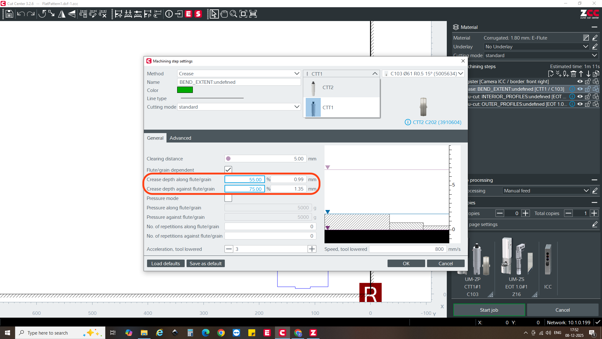
For example, within the Cut Center for "crease" we have some very particular options to choose from, here for example we may choose the depth of crease, further specifying extent of crease both with and against the grain.
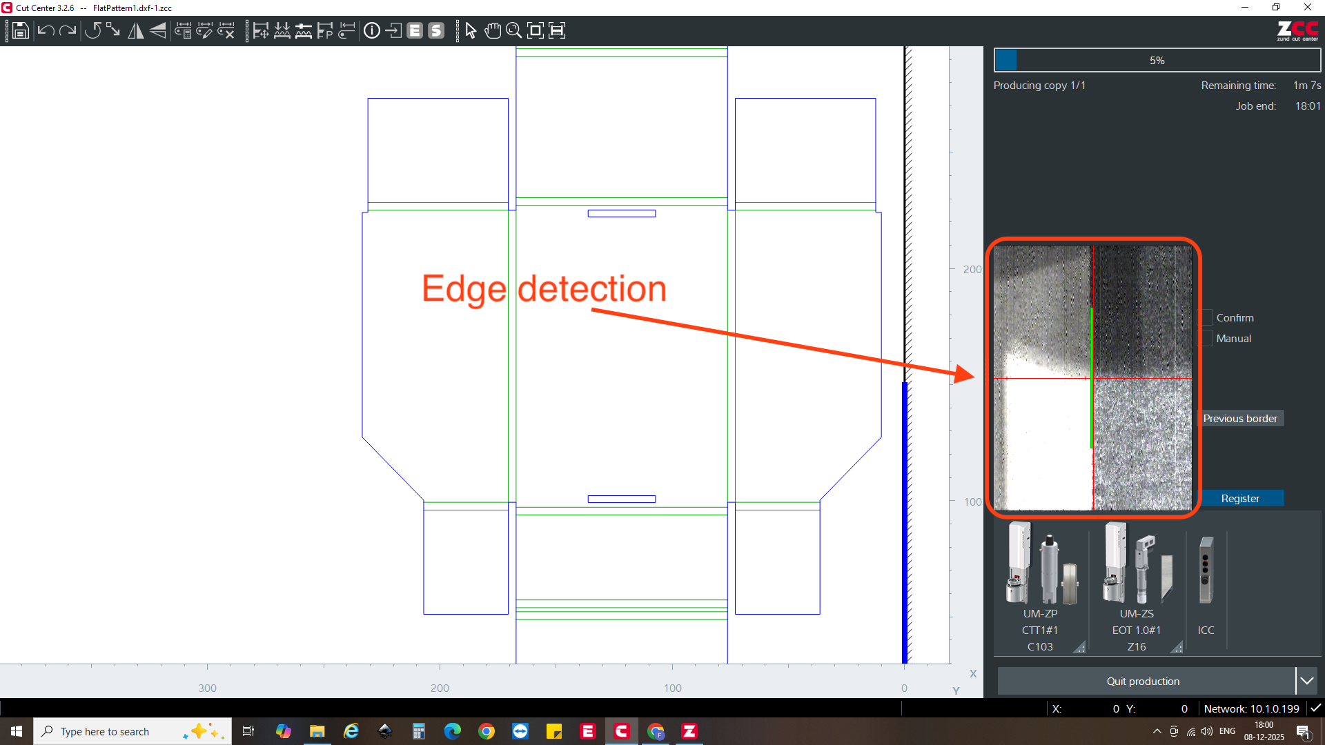
Within the Cut Center there is also a process of edge detection, where the camera on the gantry is utilized to both find and verify places on the material for cutting.
The videos below show the following processes:
Calibrating:
Creasing:
Cutting:
Result and Analysis:
Here is our freshly cut piece:
...and then in assembled form:
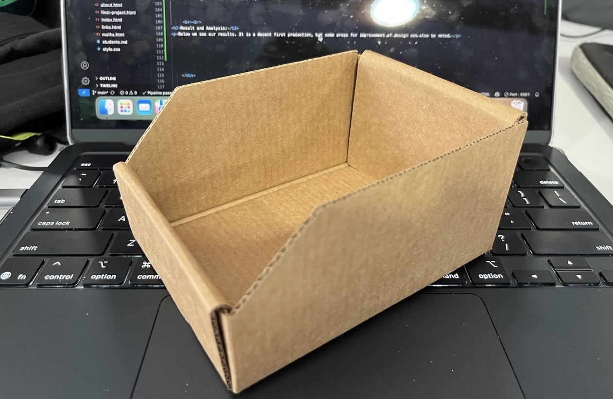
It's not bad, but not perfect either. Among areas of improvement:
- increasing length of flanges tucked under the front and back faces by offsetting.
- decreasing the length of the flanges tucked into the extruded portion.