11. Networking and Communications
Group Assignment
- Send a message between two projects
Overview
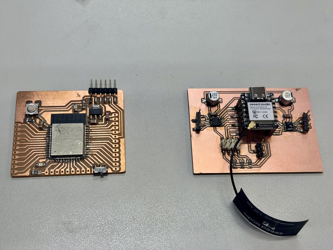
We built a wireless communication system between the custom board with XIAO ESP32-S3 and a Barduino with ESP32-DevKit-LiPo. When we press the switch connected to the custom board, the LED on the Barduino lights up — using ESP-NOW, a lightweight peer-to-peer wireless protocol from Espressif.
Demo: Switch press → LED lights up
What is ESP-NOW?
ESP-NOW is a wireless communication protocol developed by Espressif for ESP32 and ESP8266 chips. Unlike Wi-Fi or Bluetooth, it is connectionless — devices send small data packets directly to each other using MAC addresses, with no router or pairing process required.
Key characteristics:
| Feature | Detail |
|---|---|
| Protocol | Peer-to-peer, no router needed |
| Addressing | MAC address of the receiver |
| Payload size | Up to 250 bytes per packet |
| Latency | Very low (under 10 ms) |
| Range | ~200 m in open space |
| Encryption | Optional (AES-128) |
The sender registers the receiver’s MAC address as a “peer” once at startup, then calls esp_now_send() at any time to transmit data. The receiver registers a callback function that fires automatically whenever a packet arrives. There is no ongoing connection to maintain — it works like sending a letter to a known address.
This makes ESP-NOW well suited for simple, low-latency wireless triggers like the switch → LED setup in this assignment.
Setup: PlatformIO
We used PlatformIO to build and flash both boards. The project uses two separate environments in platformio.ini.
References: - Barduino programming guide (Antoine Jaunard) — Board: OLIMEX ESP32-DevKit-LiPo, Framework: Arduino - XIAO ESP32-S3 Getting Started (Seeed Wiki) - My board (Week 06)
platformio.ini
[platformio]
default_envs = xiao_esp32s3

[env:xiao_esp32s3]
platform = espressif32
board = seeed_xiao_esp32s3
framework = arduino
monitor_speed = 115200
upload_port = /dev/cu.usbmodem101
monitor_port = /dev/cu.usbmodem101
build_src_filter =
  -<*>
  +<xiao_main.cpp>

[env:barduino]
platform = espressif32
board = esp32-devkitlipo
framework = arduino
monitor_speed = 115200
upload_port = /dev/cu.usbserial-FT9OZSKA
monitor_port = /dev/cu.usbserial-FT9OZSKA
build_src_filter =
  -<*>
  +<barduino_main.cpp>
Note: The upload port won’t be detected if using a charge-only USB cable. Switching to a data cable made the port appear.
Step 1: Unit Testing Each Board
Before implementing ESP-NOW, we tested each board individually with simple serial output.
XIAO (xiao_main.cpp)
#include <Arduino.h>

void setup() {
  Serial.begin(115200);
  delay(1000);
  Serial.println("XIAO start");
}

void loop() {
  Serial.println("XIAO loop");
  delay(1000);
}
Commands:
~/.platformio/penv/bin/pio run -e xiao_esp32s3 -t upload
~/.platformio/penv/bin/pio device monitor -e xiao_esp32s3
Barduino (barduino_main.cpp)
#include <Arduino.h>

static const int LED_PIN = 13;

void setup() {
  Serial.begin(115200);
  delay(1000);
  pinMode(LED_PIN, OUTPUT);
  Serial.println("Barduino start");
}

void loop() {
  digitalWrite(LED_PIN, HIGH);
  delay(500);
  digitalWrite(LED_PIN, LOW);
  delay(500);
  Serial.println("Barduino loop");
}
For the Barduino, switch to Programming mode before uploading, then switch back to Execution mode before monitoring.
Commands:
# Upload (Programming mode + reset first)
~/.platformio/penv/bin/pio run -e barduino -t upload

# Monitor (Execution mode + reset first)
~/.platformio/penv/bin/pio device monitor -e barduino
Step 2: Get MAC Addresses via ESP-NOW
ESP-NOW requires knowing the receiver’s MAC address. We flashed a MAC-printing sketch to each board.
XIAO result:
XIAO MAC: 10:20:BA:03:93:BC
Barduino result:
Barduino MAC: C8:2B:96:9F:F7:08
Step 3: ESP-NOW Communication
Sender — XIAO (xiao_main.cpp)
The XIAO reads the switch on pin D4 (with external pull-up) and sends a message to the Barduino whenever the button state changes. Debouncing is handled in software.
#include <Arduino.h>
#include <WiFi.h>
#include <esp_now.h>

// Barduino MAC address
uint8_t receiverMac[] = {0xC8, 0x2B, 0x96, 0x9F, 0xF7, 0x08};

static const int SW_PIN = D4;

typedef struct {
  bool pressed;
  uint32_t counter;
} Message;

Message msg;

bool lastStableState = HIGH;
bool lastReading = HIGH;
unsigned long lastDebounceTime = 0;
const unsigned long debounceDelay = 30;

void onSent(const uint8_t *mac_addr, esp_now_send_status_t status) {
  Serial.print("Send status: ");
  Serial.println(status == ESP_NOW_SEND_SUCCESS ? "OK" : "FAIL");
}

void setup() {
  Serial.begin(115200);
  delay(1000);

  pinMode(SW_PIN, INPUT);  // external pull-up assumed

  WiFi.mode(WIFI_STA);
  Serial.print("XIAO MAC: ");
  Serial.println(WiFi.macAddress());

  if (esp_now_init() != ESP_OK) {
    Serial.println("ESP-NOW init failed");
    while (true) delay(1000);
  }

  esp_now_register_send_cb(onSent);

  esp_now_peer_info_t peerInfo = {};
  memcpy(peerInfo.peer_addr, receiverMac, 6);
  peerInfo.channel = 0;
  peerInfo.encrypt = false;

  if (esp_now_add_peer(&peerInfo) != ESP_OK) {
    Serial.println("Failed to add peer");
    while (true) delay(1000);
  }

  msg.pressed = false;
  msg.counter = 0;
  Serial.println("XIAO sender ready");
}

void loop() {
  bool reading = digitalRead(SW_PIN);

  if (reading != lastReading) {
    lastDebounceTime = millis();
  }

  if ((millis() - lastDebounceTime) > debounceDelay) {
    if (reading != lastStableState) {
      lastStableState = reading;
      msg.pressed = (lastStableState == LOW);
      msg.counter++;

      esp_err_t result = esp_now_send(receiverMac, (uint8_t *)&msg, sizeof(msg));

      Serial.print("Button changed -> ");
      Serial.print(msg.pressed ? "PRESSED" : "RELEASED");
      Serial.print(" / counter = ");
      Serial.print(msg.counter);
      Serial.print(" / send result = ");
      Serial.println(result == ESP_OK ? "queued" : "error");
    }
  }

  lastReading = reading;
  delay(5);
}
Upload and monitor:
~/.platformio/penv/bin/pio run -e xiao_esp32s3 -t upload
~/.platformio/penv/bin/pio device monitor -e xiao_esp32s3
Receiver — Barduino (barduino_main.cpp)
The Barduino listens for incoming ESP-NOW messages and sets LED pin 13 HIGH or LOW based on the pressed field.
#include <Arduino.h>
#include <WiFi.h>
#include <esp_now.h>

static const int LED_PIN = 13;

typedef struct {
  bool pressed;
  uint32_t counter;
} Message;

Message msg;
volatile bool ledState = false;

void onReceive(const uint8_t *mac, const uint8_t *incomingData, int len) {
  if (len != sizeof(Message)) {
    Serial.print("Unexpected packet size: ");
    Serial.println(len);
    return;
  }

  memcpy(&msg, incomingData, sizeof(msg));
  ledState = msg.pressed;

  Serial.print("Received: pressed = ");
  Serial.print(msg.pressed ? "true" : "false");
  Serial.print(", counter = ");
  Serial.println(msg.counter);
}

void setup() {
  Serial.begin(115200);
  delay(1000);

  pinMode(LED_PIN, OUTPUT);
  digitalWrite(LED_PIN, LOW);

  WiFi.mode(WIFI_STA);
  Serial.print("Barduino MAC: ");
  Serial.println(WiFi.macAddress());

  if (esp_now_init() != ESP_OK) {
    Serial.println("ESP-NOW init failed");
    while (true) delay(1000);
  }

  esp_now_register_recv_cb(onReceive);
  Serial.println("Barduino receiver ready");
}

void loop() {
  digitalWrite(LED_PIN, ledState ? HIGH : LOW);
  delay(10);
}
Upload (Programming mode + reset), then monitor (Execution mode + reset):
~/.platformio/penv/bin/pio run -e barduino -t upload
~/.platformio/penv/bin/pio device monitor -e barduino
Result
Pressing the switch on the custom board sends an ESP-NOW packet to the Barduino, which immediately turns its LED on. Releasing the switch turns it off. The counter in the message confirms each state change is transmitted correctly.
Troubleshooting Notes
| Problem | Solution |
|---|---|
| Port not visible | Use a data USB cable, not a charge-only cable |
pio not found |
Use full path: ~/.platformio/penv/bin/pio |
| Build fails | Run pio run -t clean then rebuild |
| Barduino won’t upload | Switch to Programming mode + reset before upload; switch to Execution mode + reset before monitoring |
AI usage
Claude Code was used to assist in developing the firmware for this assignment.
The process started by sharing the schematics of both boards with Claude and describing the goal in plain terms: make the two boards communicate wirelessly so that pressing the switch on the custom board causes the LED on the Barduino to light up. Claude proposed using ESP-NOW and generated the initial code for both boards.
From there, the workflow was iterative — we flashed the code, observed errors or unexpected behaviour on the serial monitor, fed that output back to Claude, and applied the suggested fixes. This loop repeated until the communication worked correctly end-to-end. No detailed technical instructions were given upfront; Claude reasoned from the schematics and the error messages.