2. Input Devices
2.1. Grove devices
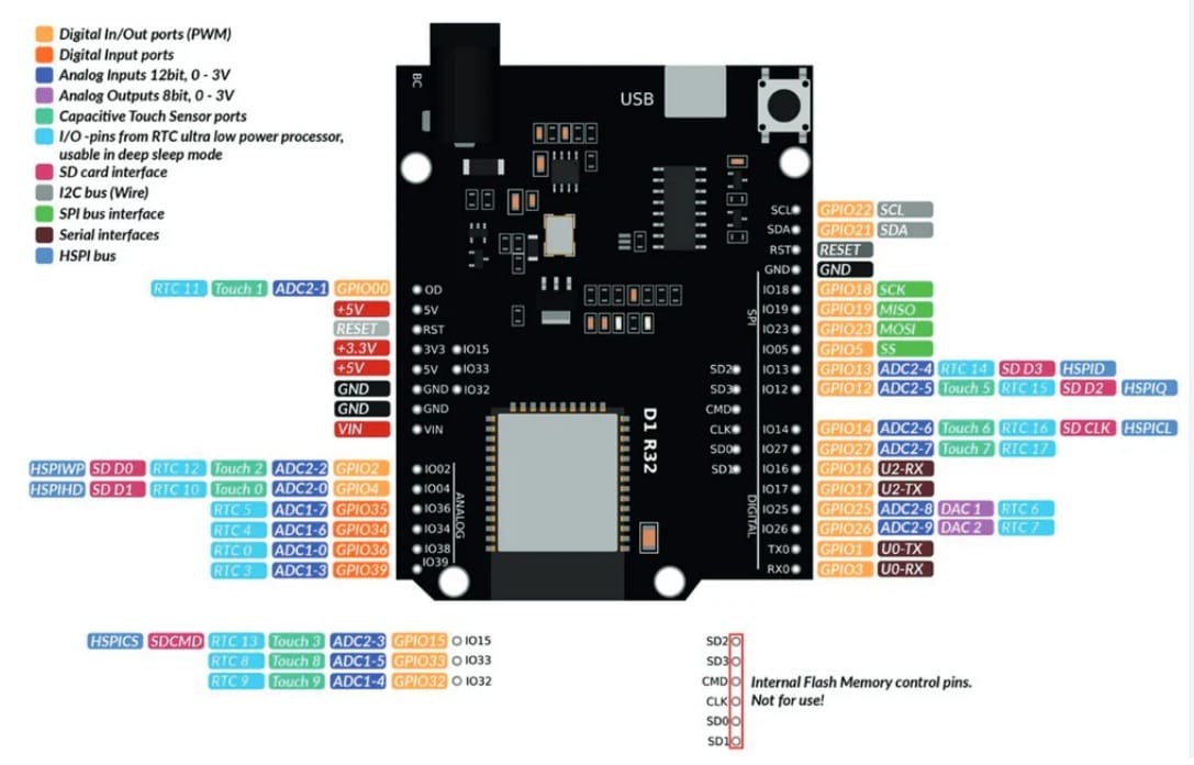
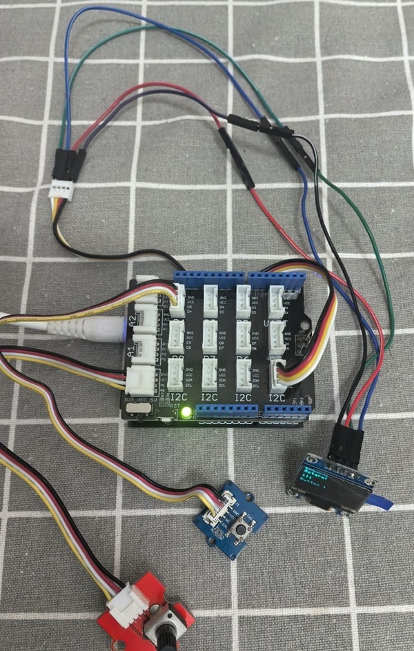
I use ESP32Uno and Seed's Base Shield Grove extension .
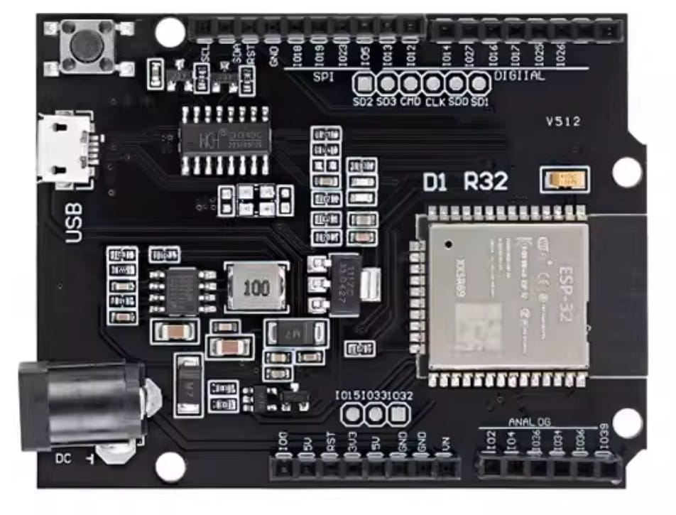
Here is the ESP32 Uno D1 pinout :
 |  |
|---|
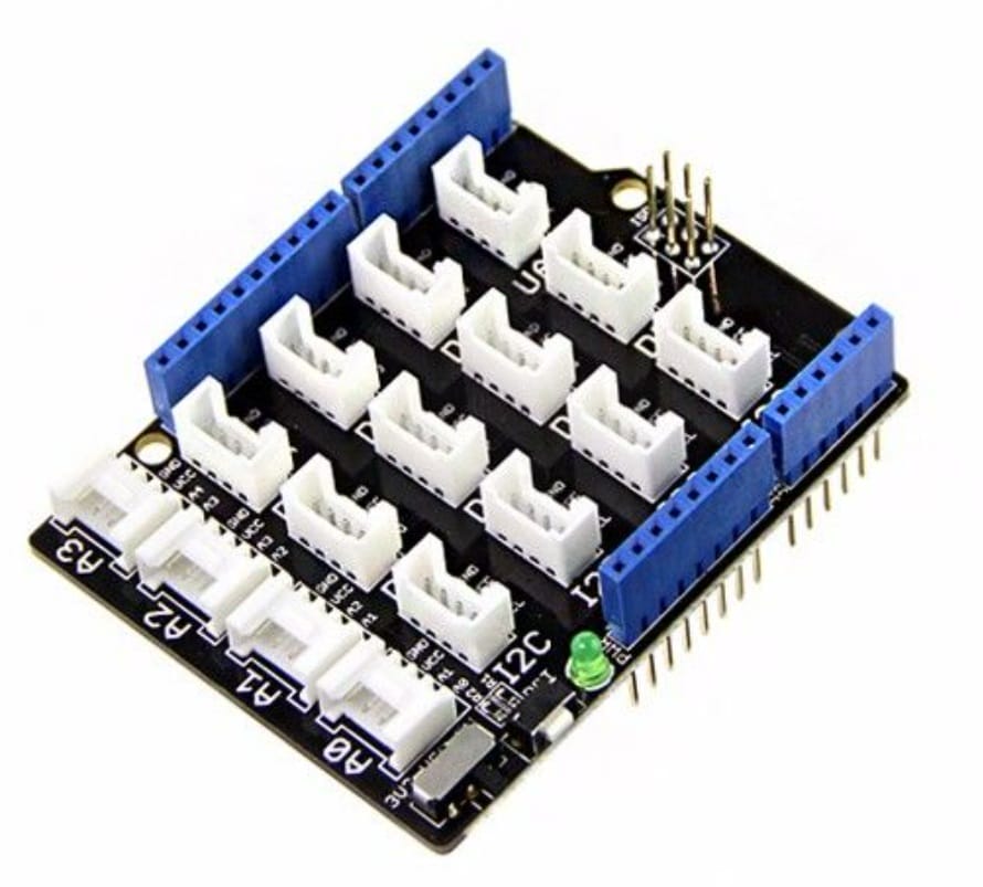
Here is the Base Shield Grove extension board:
 |  |
|---|
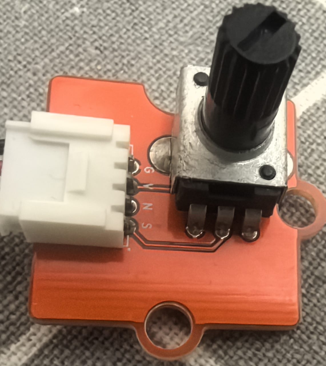
2.1.1 Rotary Potentiometer
The Grove Rotary Potentiometer is a simple, analog input module that detects rotational position.
| Pin | Function |
|---|---|
| GND | Ground |
| VCC | Power supply (3.3V/5V) |
| NC | Not connected |
| SIG | Analog output signal |
 |  |
|---|
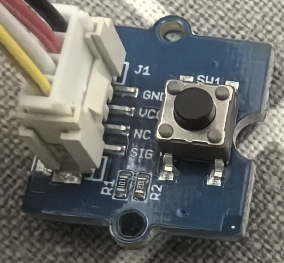
2.1.2 Button
The Grove Button is a simple, momentary push-button input module for the Grove modular electronics system.
| Pin | Function |
|---|---|
| GND | Ground |
| VCC | Power supply (3.3V/5V) |
| NC | Not connected |
| SIG | Digital signal output |
 |  |
|---|
2.2 Connection Digram
I connet Button to D4 ,and Rotate to A0. The ESP32 with Base Shield - Button and Rotary Potentiometer Connection Diagram :
2.3 coding with MicroBlocks
Here is the block code in MicroBlocks:
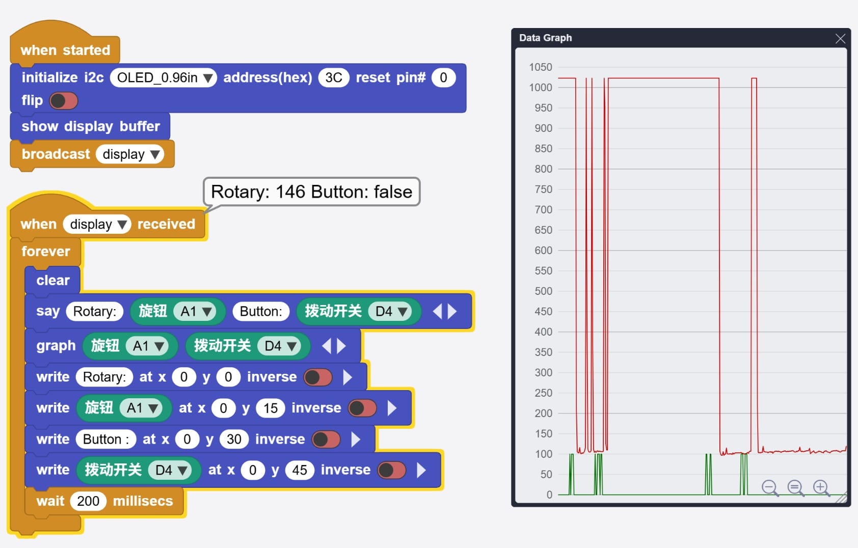
Here is the code of block code above:
script 63 82 {
whenStarted
OLEDInit_I2C 'OLED_0.96in' '3C' 0 false
OLEDshowGDBuffer
sendBroadcast 'display'
}

script 63 253 {
whenBroadcastReceived 'display'
forever {
  OLEDclear
  sayIt 'Rotary:' ('旋钮' 'A1') 'Button:' ('拨动开关' 'D4')
  graphIt ('旋钮' 'A1') ('拨动开关' 'D4')
  OLEDwrite 'Rotary:' 0 0 false
  OLEDwrite ('旋钮' 'A1') 0 15 false
  OLEDwrite 'Button :' 0 30 false
  OLEDwrite ('拨动开关' 'D4') 0 45 false
  waitMillis 200
}
}
2.3.1 Run and Debug the program
Here is the video of block code program runing in MicroBlocks:
Here is the video of testing the buttons and rotary:
2.3.2 Source
2.4 coding with VSCode+PlatformIO
Here is the platformio.ini file:
[env:esp32dev]
platform = espressif32
board = esp32dev
framework = arduino
lib_deps =
    adafruit/Adafruit SSD1306 @ ^2.5.7
    adafruit/Adafruit GFX Library @ ^1.11.5
    adafruit/Adafruit BusIO @ ^1.14.1
Here is the main.cpp file:
#include <Arduino.h>
#include <Wire.h>
#include <Adafruit_GFX.h>
#include <Adafruit_SSD1306.h>

// 根据 MicroBlocks 脚本中的映射定义
#define PIN_ROTARY 4      // A1 对应 GPIO 4
#define PIN_BUTTON 17     // D4 对应 GPIO 17

// OLED 屏幕设置
#define SCREEN_WIDTH 128
#define SCREEN_HEIGHT 64
#define OLED_RESET    -1  // 如果没有重置引脚则设为 -1
#define SCREEN_ADDRESS 0x3C

Adafruit_SSD1306 display(SCREEN_WIDTH, SCREEN_HEIGHT, &Wire, OLED_RESET);

void setup() {
    // 串口初始化(用于调试,类似于 MicroBlocks 的 sayIt)
    Serial.begin(115200);

    // 引脚模式设置
    pinMode(PIN_ROTARY, INPUT);
    pinMode(PIN_BUTTON, INPUT); // 如果扩展板没接上拉电阻,建议用 INPUT_PULLUP

    // 初始化 OLED
    if(!display.begin(SSD1306_SWITCHCAPVCC, SCREEN_ADDRESS)) {
        Serial.println(F("SSD1306 allocation failed"));
        for(;;); // 如果失败则停止
    }

    display.clearDisplay();
    display.display();

    Serial.println("System Started");
}

void loop() {
    // 1. 读取传感器数值
    int rotaryValue = analogRead(PIN_ROTARY); // 读取 A1 (0-4095)
    int buttonValue = digitalRead(PIN_BUTTON); // 读取 D4 (0 或 1)

    // 2. 串口输出 (对应 MicroBlocks 的 sayIt)
    Serial.print("Rotary: ");
    Serial.print(rotaryValue);
    Serial.print(" | Button: ");
    Serial.println(buttonValue);

    // 3. OLED 显示 (对应 MicroBlocks 的 OLEDwrite)
    display.clearDisplay();
    display.setTextSize(1);      // 字体大小
    display.setTextColor(SSD1306_WHITE);

    // 显示 Rotary 数值
    display.setCursor(0, 0);
    display.print("Rotary:");
    display.setCursor(0, 15);
    display.print(rotaryValue);

    // 显示 Button 数值
    display.setCursor(0, 30);
    display.print("Button :");
    display.setCursor(0, 45);
    display.print(buttonValue == HIGH ? "1 (OFF/Open)" : "0 (ON/Pressed)");

    // 刷新屏幕内容
    display.display();

    // 等待 200 毫秒 (对应 MicroBlocks 的 waitMillis 200)
    delay(200);
}